Digga Magnum II Series Product manual

OPERATOR’S AND PARTS MANUAL
MAGNUM MULCHER SERIES II
FOR SKID STEER AND EXCAVATOR
SERIAL NUMBER:
MODEL NUMBER:
PM-000102-A

3
READ ENTIRE OPERATOR'S & PARTS
MANUAL BEFORE
OPERATING!
DANGER! ROTATING DRUM HAZARD! STAY BACK! OBJECTS CAN BE THROWN! DO
NOT OPERATE NEAR BY STANDERS.
DANGER! TO AVOID SERIOUS PERSONAL INJURY OR DEATH THE DIGGA
MAGNUM MULCHER MUST NOT BE ATTACHED TO ANY POWER
UNIT THAT DOES NOT HAVE A FORESTRY GUARD PACKAGE
INSTALLED.
DANGER! FLYING DEBRIS HAZARD. CLEAR AREA OF BY STANDERS AND
LIVESTOCK BEFORE OPERATING. THE MULCHER IS CAPABLE OF
PRODUCING LARGE AMOUNTS OF FLYING DEBRIS IN ALL
DIRECTIONS.
WARNING! BEFORE LEAVING THE OPERATOR'S SEAT: LOWER THE LIFT ARMS
AGAINST FRAME AND PLACE UNIT ON THE GROUND. DISENGAGE
AUXILIARY HYDRAULICS. ENGAGE PARKING BRAKE. STOP ENGINE.
REMOVE THE KEY.
WARNING! THE DIGGA MULCHERS SHOULD NEVER BE OPERATED MORE
THAN 18” ABOVE THE GROUND.
NOTE: If there is any portion of this manual or function you do not understand,
contact your local authorized dealer or the manufacturer.
PM-000102-A OCTOBER 2017

4
TABLE OF CONTENTS
PREFACE ................................................................................................................................................ 5
SAFETY PRECAUTIONS
Safety Statements...................................................................................................................6
General Safety Precautions......................................................................................................7
Equipment Safety Precautions .................................................................................................9
DECALS............................................................................................................................................11
SET-UP ..................................................................................................................................................14
INSTALLATION ...........................................................................................................................................17
OPERATING INSTRUCTIONS
Intended Use.........................................................................................................................21
Case Drain ............................................................................................................................21
Push Over Bar, Hydraulic Deflector Door & Pressure Site Gauge .........................................22
Operation -Startingand Stopping the Mulcher...................................................................... 23
General Operating Tips (Ground Speed, Stalling, Jams,Mulching Brush and Trees)............ 24
Storage .................................................................................................................................25
Lift Points ..............................................................................................................................25
Tie Down Points ....................................................................................................................26
Transporting..........................................................................................................................26
MAINTENANCE AND SERVICE
Maintenance Schedule..........................................................................................................27
Lubrication Specifications......................................................................................................28
Replacing Teeth.................................................................................................................................... 29
Drive Belt Tensioning and/or Removal ...................................................................................29
Sprocket Removal and Installation ........................................................................................31
Rotor Removal and Installation .............................................................................................33
Checking and/or Changing Oil inOverhung Load Adapter.....................................................34
Replacing Skid Shoe Wear Pads ..........................................................................................35
Replacing and/or Servicing the Lower Bearings ....................................................................37
Replacing and/or Servicing the Overhung load Adapter and Hydraulic Motor ........................41
Cylinder Seal Replacement ...................................................................................................44
TROUBLESHOOTING................................................................................................................. ......47
SPECIFICATIONS
Bolt Torque Specifications .....................................................................................................52
Mulcher Specifications ..........................................................................................................53
PARTS ................................................................................................................................................... 54
LIMITED WARRANTY.....................................................................................................................................................55
PM-000102-A OCTOBER 2017
1

5
GENERAL COMMENTS
PREFACE
Congratulations on the purchase of your new DIGGA product! This product was carefully designed and
manufactured to give you many years of dependable service. Only minor maintenance, such as
cleaning and lubricating, is required to keep it in top working condition. Be sure to observe all
maintenance procedures and safety precautions in this manual and on any safety decals located on
the product and on any equipment on which the attachment is mounted. This manual has been
designed to help you do a better, safer job. Read this manual carefully and become familiar with its
contents.
WARNING! NEVER LET ANYONE OPERATE THIS UNIT WITHOUT READING THE "SAFETY
PRECAUTIONS" AND "OPERATING INSTRUCTIONS" SECTIONS OF THIS
MANUAL. ALWAYS CHOOSE HARD, LEVEL GROUND TO PARK THE VEHICLE ON
AND SET THE BRAKE SO THE UNIT CANNOT ROLL.
Unless noted otherwise, right and left sides are determined from the operator’s control position when
facing the attachment.
NOTE: The illustrations and data used in this manual were current according to the information available
to us at the time of printing, however, we reserve the right to redesign and change the attachment as
may be necessary without notification.
BEFORE OPERATION
Perform a “Hazard Assessment” of the job site and remove any possible hazards.The primary
responsibility for safety with this equipment falls to the operator. Make sure the equipment is operated
only by trained individuals that have read and understand this manual. If there is any portion of this
manual or function you do not understand, contact your local authorized dealer or the manufacturer to
obtain further assistance. Keep this manual available for reference. Provide the manual to any new
owners and/or operators.
SAFETY ALERT SYMBOL
This is the “Safety Alert Symbol” used by this industry. This symbol is used to warn of
possible injury. Be sure to read all warnings carefully. They are included for your safety
and for the safety of others working with you.
SERVICE
Use only manufacturer replacement parts. Substitute parts may not meet the required standards.
Record the model and serial number of your unit on the cover of this manual. The parts department
needs this information to insure that you receive the correct parts.
SOUND AND VIBRATION
Sound pressure levels and vibration data for this attachment are influenced by many different
parameters: some items are listed below (not inclusive):
•prime mover type, age, condition, with or without cab enclosure andconfiguration
•operator training, behavior, stress level
•job site organization, working material condition,environment
Based on the uncertainty of the prime mover, operator, and job site, it is not possible to get precise
machine and operator sound pressure levels or vibration levels for this attachment.
PM-000102-A OCTOBER 2017
3

6
SAFETY STATEMENTS
THIS SYMBOL BY ITSELF OR WITH A WARNING WORD THROUGHOUT THIS
MANUAL IS USED TO CALL YOUR ATTENTION TO INSTRUCTIONS INVOLVING
YOUR PERSONAL SAFETY OR THE SAFETY OF OTHERS. FAILURE TO FOLLOW
THESE INSTRUCTIONS CAN RESULT IN INJURY OR DEATH.
DANGER
WARNING
NOTICE
THIS SIGNAL WORD INDICATES A HAZARDOUS SITUATION WHICH, IF
NOT AVOIDED, WILL RESULT IN DEATH OR SERIOUS INJURY.
THIS SIGNAL WORD INDICATES A HAZARDOUS SITUATION WHICH, IF
NOT AVOIDED, COULD RESULT IN DEATH OR SERIOUS INJURY.
THIS SIGNAL WORD INDICATES A HAZARDOUS SITUATION WHICH, IF
NOT AVOIDED, COULD RESULT IN MINOR OR MODERATE INJURY.
Notice is used to address practices not related to physical injury.
GENERAL SAFETY PRECAUTIONS
WARNING! READ MANUAL PRIOR TO INSTALLATION
Improper installation, operation, or maintenance of this equipment could result in
serious injury or death. Operators and maintenance personnel should read this
manual, as well as all manuals related to this equipment and the prime mover
thoroughly before beginning installation, operation, or maintenance. FOLLOW ALL
SAFETY INSTRUCTIONS IN THIS MANUAL AND THE PRIME MOVER’S
MANUAL(S).
READ AND UNDERSTAND ALL SAFETY STATEMENTS
Read all safety decals and safety statements in all manuals prior to operating or
working on this equipment. Know and obey all WHS regulations, local laws, and
other professional guidelines for your operation. Know and follow good work
practices when assembling, maintaining, repairing, mounting, removing, or operating
this equipment.
KNOW YOUR EQUIPMENT
Know your equipment’s capabilities, dimensions, and operations before operating.
Visually inspect your equipment before you start, and never operate equipment that
is not in proper working order with all safety devices intact. Check all hardware to
ensure it is tight. Make certain that all locking pins, latches, and connection devices
are properly installed and secured. Remove and replace any damaged, fatigued, or
excessively worn parts. Make certain all safety decals are in place and are legible.
Keep decals clean, and replace them if they become worn or hard to read.
CAUTION
WARNING!
WARNING!
PM-000102-A OCTOBER 2017
5
7
WARNING! PROTECT AGAINST FLYING DEBRIS
Always wear proper safety glasses, goggles, or a face shield when driving pins in or
out, or when any operation causes dust, flying debris, or any other hazardous
material.
WARNING! LOWER OR SUPPORT RAISED EQUIPMENT
Do not work under raised booms without supporting them. Do not use support
material made of concrete blocks, logs, buckets, barrels, or any other material that
could suddenly collapse or shift positions. Make sure support material is solid, not
decayed, warped, twisted, or tapered. Lower booms to ground level or on blocks.
Lower booms and attachments to the ground before leaving the cab or operator’s
station.
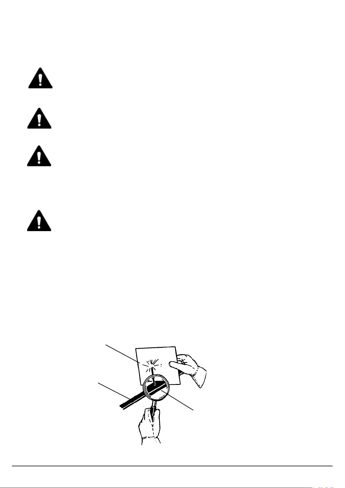
WARNING! USE CARE WITH HYDRAULIC FLUID PRESSURE
Hydraulic fluid under pressurecan penetrate the skin and cause serious injury or
death. Hydraulic leaks under pressure may not be visible. Before connecting or
disconnecting hydraulic hoses, read your prime mover’s operator’s manual for
detailed instructions on connecting and disconnecting hydraulic hoses or fittings.
•Keep unprotected body parts, such as face, eyes, and arms asfar away as
possible from a suspected leak. Flesh injected with hydraulic fluid may develop
gangrene or other permanent disabilities.
•If injured by injected fluid, see adoctor at once. If your doctor is not familiar with
this type of injury, askhim to researchit immediately to determine proper
treatment.
•Wear safety glasses,protective clothing, and use a piece of cardboard or wood
when searching for hydraulic leaks. DO NOT USE YOUR HANDS! SEE
ILLUSTRATION.
CARDBOARD
HYDRAULIC HOSE
OR FITTING
MAGNIFYING GLASS
GENERAL SAFETY PRECAUTIONS
WARNING! HAZARD ASSESMENT
Evaluate the work space for potential hazards you may encounter whilst operating
the Mulcher.
PM-000102-A OCTOBER 2017
6

8
WARNING! DO NOT MODIFY MACHINE OR ATTACHMENTS
Modifications may weaken the integrity of the attachment and may impair the
function, safety, life, and performance of the attachment. When making repairs, use
only the manufacturer’s genuine parts, following authorized instructions. Other parts
may be substandard in fit and quality. Never modify any ROPS (Roll Over
Protective Structure) or FOPS (Falling Object Protective Structure) equipment or
device. Any modifications must be authorized in writing by the manufacturer.
WARNING! SAFELY MAINTAIN AND REPAIR EQUIPMENT
•Do not wear loose clothing or any accessories that can catch inmoving parts. If
you have long hair, cover or secure itsothat itdoes not become entangled in the
equipment.
•Work on a level surface in a well-lit area.
•Use properly grounded electrical outlets and tools.
•Use the correct tools for the job at hand.Make surethey are ingood condition for
the task required.
•Wear the protective equipment specified by the tool manufacturer.
SAFELY OPERATE EQUIPMENT
Do not operate equipment until you are completely trained by a qualified operator
in how to use the controls, know its capabilities, dimensions, and all safety
requirements. See your machine’s manual for these instructions.
•Keep all step plates, grab bars, pedals, and controls free of dirt, grease, debris,
and oil.
•Never allow anyone to be around the equipment when it is operating.
•Do not allow riders on the attachment or the prime mover.
•Do not operate the equipment from anywhere other than the correct operator’s
position.
•Never leave equipment unattended with the engine running, or with this
attachment in a raised position.
•Do not alter or remove any safety feature from the prime mover or this
attachment.
•Know your work site safety rules as well as traffic rules and flow. When in doubt
on any safety issue, contact your supervisor or safety coordinator for an
explanation.
WARNING!
GENERAL SAFETY PRECAUTIONS
PM-000102-A OCTOBER 2017
7

9
WARNING! KNOW WHERE UTILITIES ARE
Observe overhead electrical and other utility lines. Be sure equipment will clear
them. When digging, call your local utilities for location of buried utility lines, gas,
water, and sewer, as well as any other hazard you may encounter.
WARNING! EXPOSURE TO RESPIRABLE CRYSTALLINE SILICA DUST
ALONG WITH OTHER HAZARDOUS DUSTS MAY CAUSE
SERIOUS OR FATAL RESPIRATORY DISEASE.
It is recommended to use dust suppression, dust collection and if necessary personal
protective equipment during the operation of any attachment that may cause high
levels of dust.
WARNING! REMOVE PAINT BEFORE WELDING OR HEATING
Hazardous fumes/dust can be generated when paint is heated by welding, soldering
or using a torch. Do all the work outside or in a well ventilated area and dispose of
paint and solvent properly. Remove paint before welding or heating.
When sanding or grinding paint, avoid breathing the dust. Wear an approved
respirator. If you use solvent or paint stripper, remove stripper with soap and water
before welding. Remove solvent or paint stripper containers and other flammable
material from area. Allow fumes to disperse at least 15 minutes before welding or
heating.
WARNING! END OF LIFE DISPOSAL
At the completion of the useful life of the unit, drain all fluids and dismantle by
separating the different materials (rubber, steel, plastic, etc.). Follow all federal,
state and local regulations for recycling and disposal of the fluid andcomponents.
OPERATING THE MULCHER
•Block off work area from bystanders, livestock, etc. Flying debris can cause
severe injury or death. The mulcher is capableof producing large amounts of
flying debris inalldirections.
•Do NOT operate without aforestry guard package installed on the prime mover.
•Operate only from the operator’s station.
•Be aware when mulching standing trees, there is a danger of the treetop falling
back ontothe operator’s cab.
•Do not engage or disengage the drum while the engine rpm’s are above.
•Whenmounted onto a skid steer loader, do not operate the mulcher with the
attachment over 18”above the ground.
•Do not lift loads in excess of the capacity of the prime mover. Lifting capacity
decreases as the loader is moved further away from the unit.
•When operating on slopes, drive up and down, not across. Avoid steep hillside
operation, which could cause the primemover tooverturn.
•Reduce speed when driving over roughterrain, on a slope, or turning, toavoid
overturning the vehicle.
•An operator must notuse drugs or alcohol, which can change his orher
alertness or coordination. An operator taking prescription or over-the-counter
drugs should seek medical advice on whether ornothe or she can safely
operate equipment.
•Before exiting the primemover, roll the attachment backand lower ittothe
ground, applybrakes, turnoff the prime mover’s engine, and removethe key.
WARNING!
EQUIPMENT SAFETY PRECAUTIONS
PM-000102-A OCTOBER 2017
8

10
TRANSPORTING THE MULCHER
•Travel only with the attachment in a safe transport position to prevent
uncontrolled movement. Drive slowly over rough ground and on slopes.
•Whentransporting on a trailer: Secure attachment atrecommended tie down
locations using tie down accessories that are capable of maintaining attachment
stability.
•When driving on public roads usesafety lights, reflectors, and Slow Moving
Vehicle signs etc. to prevent accidents. Check local government regulations that
may affect you.
•Do not drive close to ditches, excavations, etc., cave in could result.
•Do not smoke when refueling the prime mover. Allow room in the fuel tank for
expansion. Wipe up any spilled fuel. Secure cap tightly when done.
MAINTAINING THE MULCHER
•Before performing maintenance, disengage auxiliary hydraulics, lower the
attachment to the ground, turn off the engine, removethe key and apply the
brakes.
•Never perform any work on the attachment unless you are authorized and
qualified to do so. Always read the operator manual’s before any repair is made.
After completing maintenanceor repair, check for correct functioning of the
attachment. Ifnotfunctioning properly, always tag “DO NOT OPERATE” until all
problems are corrected.
•Worn, damaged, or illegible safety decals must be replaced. New safety decals
can be ordered from DIGGA.
•Never make hydraulic repairs while the system is under pressure. Serious
personal injury or death could result.
•Never work undera raised attachment.
WARNING!
WARNING!
EQUIPMENT SAFETY PRECAUTIONS
PM-000102-A OCTOBER 2017
9
11
#40591
#40719
#4167
#41200
#40151
#40719
#40591
#4167
MODEL
NUMBER
#41192
#4105
#41020
LOGO
#41087
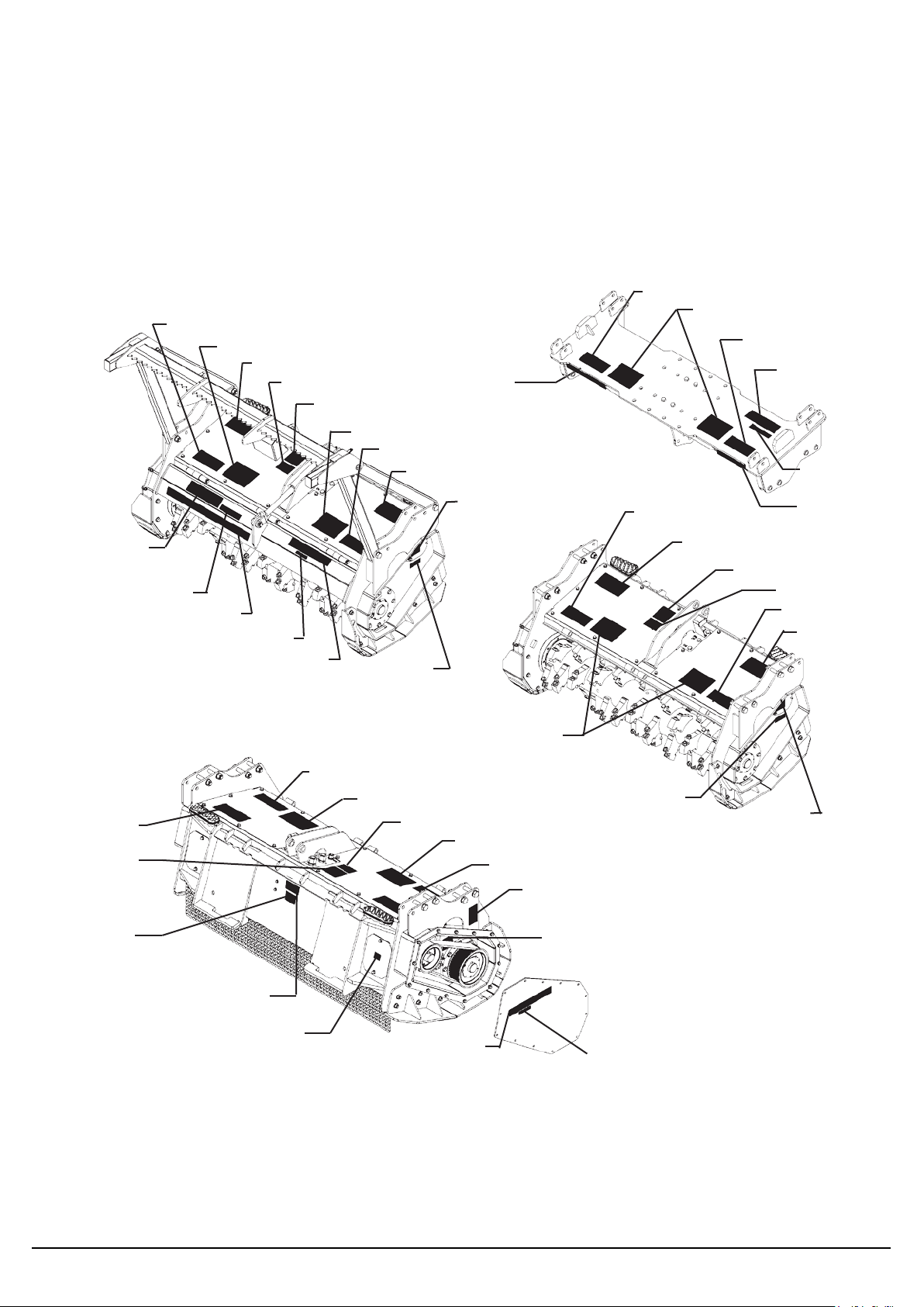
GENERAL INFORMATION
DECAL PLACEMENT
The diagram on this page shows the location of the decals used on the DIGGA Mulchers. The decals
are identified by their part numbers, with reductions of the actual decals located on the following
pages. Use this information to order replacements for lost or damaged decals. Be sure to read all
decals before operating the attachment. They contain information you need to know for both safety and
longevity.
#40161
#40591
#40719
#40591
MODEL
NUMBER
#41059
#40591
#4167
#40151
#41020
#40161
#41200
#40591
#4167
#4167
#40151
#40591
#40719
#41200
#40719
#40719
#40591
#41087
#41059
#40949
#41204 #40307
SERIAL TAG LOCATION
#4132
LOGO #41020
IMPORTANT: Keep all safety signs clean and legible. Replace all missing, illegible, or damaged safety
signs. When replacing parts with safety signs attached, the safety signs must also be replaced.
REPLACING SAFETY SIGNS: Clean the area of application with nonflammable solvent, then wash
the same area with soap and water. Allow the surface to fully dry. Remove the backing from the safety
sign, exposing the adhesive surface. Apply the safety sign to the position shown in the diagram above
and smooth out any bubbles.
DECALS
PM-000102-A OCTOBER 2017
10

12
DANGER! FLYING DEBRIS
PART #40719
WARNING! HIGH PRESSURE FLUID
PART #40151
DANGER! ROTATING DRUM
PART #40591
DANGER! STAND CLEAR
PART #4105 WARNING! GUARDS
PART #40949
CLEAN DEBRIS - 40 HOURS
PART #41087
DANGER! GUARD MISSING
PART #40307
NOTICE! MOTOR FAILURE
PART #41200
DECALS
PM-000102-A OCTOBER 2017
11
13
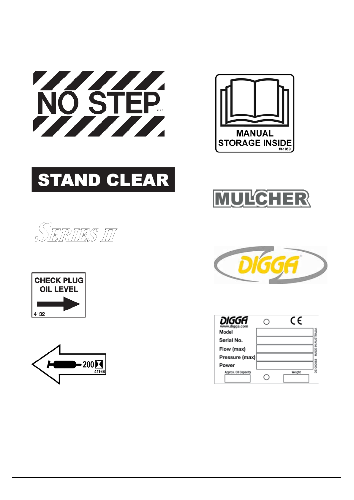
NO STEP
PART #4167
STAND CLEAR
PART #40161
SERIES II
PART #41192
MANUAL STORAGE INSIDE
PART #41059
MULCHER LOGO
PART #41020
GREASEEVERY 200 HOURS
PART #41166
CHECK OIL LEVEL
PART #4132
NOTE: Contact your local dealer for model number and logo decals.
DIGGA LOGO
SERIAL TAG
PART #DE000063
DECALS
PM-000102-A OCTOBER 2017
12

14
MINIMUM DISPLACEMENT
SCREW
“X”
BEST RESULTS ARE OBTAINED WHEN
MEASURED WITH A DIGITAL CALIPER.
NOTE: These mulchers include a 6mm allen wrench and 19mm wrench to adjust the displacement
screws.
SETUP
MOTOR DISPLACEMENT
Due tothe range ofprime movers the DIGGA Series IIMagnum Mulcher isdesigned for, the motor
minimum displacement isadjustableto various LPM and rotor RPM togive you optimum productivity
for your particular application. The displacement must be adjusted and then “locked in”. For optimum
productivity and proper operation the minimum displacement on the mulcher motor needs to be
adjusted for the “ACTUAL” LPM of your primemover and the desired RPM of the mulcher rotor. With
the engine at full throttle, setthe rotor RPM between 1800 -2000 RPM. (Factory settings are 50 CC on
all skid steer loader mulchers, 66 CC on the combination and excavator mulchers and 76 CC on the
forestry mulchers.)
NOTICE:Insufficient RPM (below 1800) will greatly reduce the productivity ofyour unit while over
speeding (above 2000) can causeserious damage to the motor and teeth.
See the following charts for correct adjustment of the minimum displacement screw for the motor
minimum displacement.
NOTE: To Adjust Minimum Displacement Screw, loosen and hold the locking nut while turning the
minimum displacement screw tothe desired dimension and then holdthe limit screw while turning the
locking nutand therefore locking it inplace.
It isrecommended that the drum RPM be checked with a tachometer after adjustments have been
completed. Toincrease RPM, increase “X” dimension. To decrease RPM decrease the “X” dimension.
The maximum displacement limit screw is adjusted at the factory.
IMPORTANT:Primemover must be at operating temperature prior to checking the rotor RPM with
tachometer.
PM-000102-A OCTOBER 2017
13

15
LPM DISPLACEMENT
(CC)
SCREW
(M12X100 )
DIMENSION X
(mm)
DISPLACEMENT
(CC)
SCREW
(M12X100 )
DIMENSION X
(mm)
DISPLACEMENT
(CC)
SCREW
(M12X100 )
DIMENSION X
(mm)
113.55
44.20 30.73 41.80 32.00 39.70 33.27
117.34
45.60 29.97 43.20 31.24 41.10 32.51
121.12
47.10 29.21 44.60 30.48 42.40 31.75
124.91
48.60 28.19 46.00 29.72 43.70 30.99
128.69
50.10 27.43 47.40 28.96 45.00 30.23
132.48
51.50 26.67 48.80 28.19 46.40 29.46
136.26
53.00 25.65 50.20 27.43 47.70 28.70
140.05
54.50 24.89 51.60 26.42 49.00 27.94
143.83
55.90 24.13 53.00 25.65 50.30 27.18
147.62
57.40 23.11 54.40 24.89 51.70 26.42
151.40
58.90 22.35 55.80 24.13 53.00 25.65
155.19
60.40 21.59 57.20 23.37 54.30 24.89
158.97
61.80 20.57 58.60 22.61 55.60 24.13
162.76
63.30 19.81 60.00 21.84 57.00 23.37
166.54
64.80 19.05 61.40 20.83 58.30 22.61
170.33
66.30 18.03 62.80 20.07 59.60 21.84
LPM DISPLACEMENT
(CC)
SCREW
(M12X100 )
DIMENSION X
(mm)
DISPLACEMENT
(CC)
SCREW
(M12X100 )
DIMENSION X
(mm)
DISPLACEMENT
(CC)
SCREW
(M12X100 )
DIMENSION X
(mm)
132.48
65.40 30.48 62.00 32.26 58.90 33.53
136.26
67.30 29.72 63.70 31.24 60.60 32.77
140.05
69.20 28.96 65.50 30.48 62.20 32.00
143.83
71.00 27.94 67.30 29.72 63.90 31.24
147.62
72.90 27.18 69.10 28.96 65.60 30.48
151.40
74.80 26.16 70.80 28.19 67.30 29.72
155.19
76.60 25.40 72.60 27.18 69.00 28.96
158.97
78.50 24.64 74.40 26.42 70.70 28.19
162.76
80.40 23.62 76.10 25.65 72.30 27.43
166.54
82.30 22.86 77.90 24.89 74.00 26.67
170.33
84.10 21.84 79.70 23.88 75.70 25.91
1900 ROTOR RPM 2000 ROTOR RPM
60” SKID STEER ONLY MULCHERS 113.5-170.3 LPM / 80CC(107251
HYDRAULIC MOTOR / 35T & 50T SPROCKETS)
60” FORESTRY MULCHERS 132.48-170.33 LPM / 107CC (200-169
HYDRAULIC MOTOR / 40T & 45T SPROCKETS)
1800 ROTOR RPM
1800 ROTOR RPM
2000 ROTOR RPM1900 ROTOR RPM
SETUP
PM-000102-A OCTOBER 2017
14

16
LPM
DISPLACEMENT
(CC)
SCREW
(M12X100 )
DIMENSION X
(mm)
DISPLACEMENT
(CC)
SCREW
(M12X100 )
DIMENSION X
(mm)
DISPLACEMENT
(CC)
SCREW
(M12X100 )
DIMENSION X
(mm)
113.55 44.20 40.39 41.80 41.40 39.70 42.42
117.34 45.60 39.62 43.20 40.89 41.10 41.91
121.12 47.10 39.12 44.60 40.13 42.40 41.15
124.91 48.60 38.35 46.00 39.62 43.70 40.64
128.69 50.10 37.59 47.40 38.86 45.00 39.88
132.48 51.50 37.08 48.80 38.35 46.40 39.37
136.26 53.00 36.32 50.20 37.59 47.70 38.86
140.05 54.50 35.56 51.60 37.08 49.00 38.10
143.83 55.90 35.05 53.00 36.32 50.30 37.59
147.62 57.40 34.29 54.40 35.56 51.70 36.83
151.40 58.90 33.53 55.80 35.05 53.00 36.32
155.19 60.40 33.02 57.20 34.29 54.30 35.81
158.97 61.80 32.26 58.60 33.78 55.60 35.05
162.76 63.30 31.50 60.00 33.02 57.00 34.54
166.54 64.80 30.99 61.40 32.51 58.30 33.78
170.33 66.30 30.23 62.80 31.75 59.60 33.27
174.11 67.70 29.46 64.20 31.24 60.90 32.77
177.90 69.20 28.96 65.60 30.48 62.30 32.00
181.68 70.70 28.19 66.90 29.97 63.60 31.50
185.47 72.10 27.43 68.30 29.21 64.90 30.73
189.25 73.60 26.67 69.70 28.70 66.20 30.23
193.04 75.10 26.16 71.10 27.94 67.60 29.46
196.82 76.60 25.40 72.50 27.18 68.90 28.96
200.61 78.00 24.64 73.90 26.67 70.20 28.45
204.39 79.50 24.13 75.30 25.91 71.50 27.69
208.18 81.00 23.37 76.70 25.40 72.90 27.18
211.96 82.50 22.61 78.10 24.64 74.20 26.42
215.75 83.90 22.10 79.50 24.13 75.50 25.91
219.53 85.40 21.34 80.90 23.37 76.80 25.40
223.32 86.90 20.57 82.30 22.86 78.20 24.64
227.10 88.30 20.07 83.70 22.10 79.50 24.13
1900 ROTOR RPM
2000 ROTOR RPM
60” SKID STEER ONLY MULCHERS 113.55-170.3 LPM / 107CCAND
60” COMBINATION AND EXCAVATOR ONLY MULCHERS 113.6-227.10 LPM / 107CC
(200-169 HYDRAULIC MOTOR / 35T & 50T SPROCKETS)
1800 ROTOR RPM
SETUP
PM-000102-A OCTOBER 2017
15

17
PUSH OVER BAR
CYLINDER
RIGHT COMPARTMENT
COVER
PRESSURE GAUGE
LEFT COMPARTMENT
COVER
EXCAVATOR
MOUNTING PLATE
SKID
SHOE
ROTOR
DEFLECTOR
DOOR
SKID
SHOE
MAINFRAME
SKID SHOE LOWER BEARING
ASSEMBLY
ROTOR
SKID
SHOE
MAINFRAME
LOWER
BEARING
ASSEMBLY
DRIVE SPROCKETS
DRIVE COVER
DRIVE BELT
LOWER BEARING ASSEMBLY
MAINTENANCE
COVER
RIGHT SIDE OF MULCHER
SKID STEER ONLY EXCAVATOR ONLY
SAFETY
CHAINS
INSTALLATION
GENERAL INFORMATION
TheDIGGA Series IIMagnum Mulchers were designed to be easy touse and maintain. The 60”
mulchers areavailablewith skid steer onlymounting, excavator onlymounting or a combination
mulcher that canbe easily changed from skid steer mounting toexcavator mounting. A special 60”
mulcher isdesigned for a universal skid steer hitch forestry vehicle. When installing a hydraulic 3-line
mulcher onto your primemover acontrol box assembly #15754 or a pigtail adaptor harness for in-
cab controls isrequired to operate the deflector door.
NOTICE: Do not operate the Digga Series II mulchers on standard flow hydraulic systems.
NOMENCLATURE
Throughout this manual, reference is made tovarious mulcher components. Study the following
diagrams to acquaint yourself with the various names ofthese components. The combination
mulcher isnot shown but has components from both attachments shown below. This knowledge will
be helpful when reading through this manual orwhen ordering service parts. There is a complete
parts breakdownfor each mulcher at the back ofthis manual.
PM-000102-A OCTOBER 2017
16

18
SECURELY LATCHED TO THE ATTACHMENT MECHANISM OF YOUR UNIT.
FAILURE TO DO SO COULD RESULT IN SEPARATION OF THE ATTACHMENT
FROM THE UNIT. CLEAR THE AREA OF ALL BYSTANDERS DURING
INSTALLATION.
ATTACHING -EXCAVATOR
A separate mounting kit is required to install the DIGGA Series II Mulcher onto your excavator. Install
the mounting bracket to the mulcher mounting plate. Install the mulcher to your excavator by following
your prime mover operator’s manual for proper installation of an attachment. When attaching the
hoses to the excavator, the case drain line (“CD” port) must be connected first, then the power (“P”
port) and return (“T” port) hoses. When disconnecting the hoses, it is recommended to disconnect the
case drain line last. This will prevent any over pressurization of the motor case on the mulcher head.
NOTE: The case drain line must be installed from the mulcher head to the excavator hydraulic tank.
The case drain line must be unrestricted all the way to the tank.
IMPORTANT: Over pressurization of motor case can be caused by a kinked or pinched hose, improper
connection and obstruction or damaged coupler on the case drain line. Make any necessary
adjustments and/or reroute hoses before operating. Route hoses in such a fashion to prevent pinching
or chafing.
WARNING! TO AVOID SERIOUS PERSONAL INJURY, MAKE SURE THE MULCHER IS
SECURELY LATCHED TO THE ATTACHMENT MECHANISM OF YOUR UNIT.
FAILURE TO DO SO COULD RESULT IN SEPARATION OF THE ATTACHMENT
FROM THE UNIT. CLEAR THE AREA OF ALL BYSTANDERS DURING
INSTALLATION.
INSTALLATION
NOTE:Before attaching the mulcher to your prime mover, make sure a forestry guard package has
been installed onto the primemover. This isrequired toprotect the operator from possible thrown
objects.
ATTACHING -UNIVERSAL SKID STEERMOUNTING
Install the DIGGA Series IIMulcher by following your primemover operator’s manual for proper
installation of an attachment. When attaching the hoses tothe primemover, the case drainline (“CD”
port) must be connected first, then the power (“P” port) and return (“T” port) hoses.
When disconnecting the hoses, itisrecommended to disconnectthe case drain line last. This will
prevent any over pressurization of the motor caseon the mulcher head. Foroperation of the deflector
door on 3-line hydraulic mulcher, install control box #15754 to electrical harness on mulcher orinstall a
pigtail adapter to adapt the wiring harness on the mulcher to your in-cab controls (if so equipped).
IMPORTANT:Over pressurization of motor casecan be caused by akinked or pinched hose, improper
connection and obstruction or damaged coupler on the case drain line.
Make any necessary adjustments and/or reroute hoses before operating. Routehoses in such a fashion
to prevent pinching or chafing.
WARNING! TO AVOID SERIOUS PERSONAL INJURY, MAKE SURE THE MULCHER IS
PM-000102-A OCTOBER 2017
17

19
ATTACHING -COMBINATION MULCHER
The combination mulcher can be mounted to a skid steer loader or excavator.
NOTE: The attachment ships skid steer ready. See “CHANGING COMBINATION MULCHER
MOUNTING” for changing from skid steer mounting to excavator mounting and back again.
Install the mulcher to your skid steer or excavator by following your prime mover’s operator’s manual
for proper installation of an attachment. When attaching the hoses, the case drain line (“CD” port) must
be connected first, then the power (“P” port) and return (“T” port) hoses.
When disconnecting the hoses, it is recommended to disconnect the case drain line last. This will
prevent any over pressurization of the motor case on the mulcher head.
NOTE: If installing onto an excavator the case drain line must be installed from the mulcher head to
the excavator hydraulic tank. The case drain line must be unrestricted all the way to the tank.
IMPORTANT: Over pressurization of motor case can be caused by a kinked or pinched hose, improper
connection and obstruction or damaged coupler on the case drain line. Make any necessary
adjustments and/or reroute hoses before operating. Route hoses in such a fashion to prevent pinching
or chafing.
WARNING! TO AVOID SERIOUS PERSONAL INJURY, MAKE SURE THE MULCHER IS
SECURELY LATCHED TO THE ATTACHMENT MECHANISM OF YOUR UNIT.
FAILURE TO DO SO COULD RESULT IN SEPARATION OF THE ATTACHMENT
FROM THE UNIT. CLEAR THE AREA OF ALL BYSTANDERS DURING
INSTALLATION.
DETACHING
On firm, level ground. Lower the mulcher to the ground. Follow your prime mover operator’s manual to
relieve pressure in the hydraulic lines. Disconnect couplers. When disconnecting the hoses, it is
recommended to disconnect the case drain line last. This will prevent any over pressurization of the motor
case on the mulcher head.
NOTE: Connect couplers together or install dust caps and plugs to prevent contaminants from
entering the hydraulic system. Store hoses on attachment off the ground.
Disconnect the auxiliary electrical connection or the control box from the prime mover and secure the
wire harness to the attachment (if so equipped).Follow your prime mover operator’s manual for
detaching (removing) an attachment.
WARNING! CLEAR THE AREA OF ALL BYSTANDERS DURING REMOVAL.
IMPORTANT: Disengage the auxiliary hydraulics, stop the engine, engage parking brake and remove
key before leaving the operator’s station.
INSTALLATION
PM-000102-A OCTOBER 2017
18

20
CHANGING COMBINATION MULCHER MOUNTING
The combination mulcher can be mounted to a skid steer loader or excavator with very few changes.
The attachment ships skid steer ready.
TO CHANGE FROM SKID STEER LOADER TO EXCAVATOR MOUNTING:
1. Install the excavator mount(s).
2. Retract the cylinder and remove the deflector door.
NOTE: The cylinder can remain on theunit.
3. Disconnect electrical connection. (Disconnect mulcher electrical harness from control box
#15754 or pigtail adaptor going to in-cab electrical outlet.)
4. Remove the push over bar.
5. Adjust motor displacement for correct rotor RPM. See Set-Up instructions.
TO CHANGE FROM EXCAVATOR MOUNTING TO SKID STEER LOADER MOUNTING:
1. Remove the excavator mount(s).
2. Install the deflector door.
3. Connect the cylinder to the deflector door.
4. Reinstall the push over bar using the existinghardware.
5. Reinstall electrical connection. (Connect mulcher electrical harness to control box #15754 or
pigtail adaptor going to in-cab electricaloutlet.)
6. Adjust motor displacement for correct rotor RPM. See Set-Up instructions.
INSTALLATION
PM-000102-A OCTOBER 2017
19
Table of contents
Other Digga Farm Equipment manuals


Popular Farm Equipment manuals by other brands


Schmeiser
Schmeiser Bantam Leveler BOL 080 Operation and parts manual

Kerbl
Kerbl 70550 operating instructions

TURFCO
TURFCO T3100 Service Quick Guide

AG SPRAY
AG SPRAY FSSS-60-12V owner's manual

Kemper
Kemper Champion C 1200 operating manual

McFarlane
McFarlane RD-4000 Series OPERATOR'S MANUAL AND PARTS LISTING


