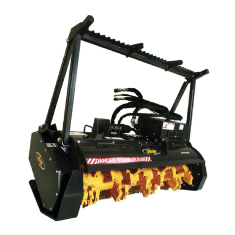
Digga SLASHA User manual

SLASHA
OPERATORS MANUAL
PM-000084-D

2
PM-000084-D - Slasher Operators Manual - OCTOBER 2017
Congratulations on the purchase of your new DIGGA Slasher! This product was carefully designed and manufactured to give you years of
dependable service. To keep it running efciently please read the instructions in the manual to keep it in top working condition.
Be sure to observe all safety precautions and maintenance procedures as described in this manual.
No responsibility will be taken by Digga for any omissions or errors in this manual as all data is correct at time of print, however Digga
reserve the right to revise this manual without further notice.
The Slasher has mutlit mounting. Please contact your DIGGA dealer for any further information pertaining to this product or for further
information on other Digga products.
1 TO THE PURCHASER
ABOUT THIS MANUAL
This manual has been designed to help you do a better,
safer job. Read this manual carefully and
become familiar with its contents.Remember;
never let anyone operate this unit without reading the
“Safety Precautions” and “Operating Instructions”
sections of this manual. Unless noted otherwise, right and
left sides are determined from the position of the operator
when behind the product facing forward.
MODEL______________________________________
SERIAL NUMBER______________________________
DATE PURCHASED____________________________
The parts department needs this information
to insure accurate parts can be sent to the
authorised service agent.
Your Digga Slasher is a user non serviceable part. Unauthorised disassembly will void warranty. All service and warranty
must be performed by an authorised DIGGA service agent. Contact your local Digga dealer for details. To facilitate warranty or
service, record the model and serial number of your unit in the space provided on this page.
This information may be obtained from the identication plate located on the product.
IMPORTANT: WHEN SERVICING OR ASSEMBLING YOUR PRODUCT, REMEMBER TO USE ONLY GENUINE
DIGGA REPLACEMENT PARTS. SUBSTITUTE PARTS MAY NOT MEET THE STANDARDS REQUIRED FOR
SAFE, DEPENDABLE OPERATION. USE OF NON GENUINE DIGGA PARTS WILL VOID WARRANTY AND
DIGGA WILL ACCEPT NO LIABILITY WHAT SO EVER FOR CONSEQUENTIAL OR SPECIAL DAMAGES.

3
PAGE
1 TO THE PURCHASER....................................................................... 3
2 TABLE OF CONTENTS....................................................................... 4
3 PREPARATION FOR USE................................................................... 5
4 SAFETY PRECAUTIONS..................................................................... 6
5 SAFETY - WORKING WITH THE ATTACHMENTS.............................. 11
6 INSTALLATION AND OPERATING INSTRUCTIONS........................... 12
7 SPARE PARTS.................................................................................... 16
8 MAINTENANCE.................................................................................. 18
9 SAFETY STICKER LOCATION........................................................... 20
10 TROUBLESHOOTING........................................................................ 22
11 TECHNICAL SPECIFICATIONS......................................................... 23
12 WARRANTY........................................................................................ 24
2 TABLE OF CONTENTS
SLASHA STANDARD MODELS SLASHA EXCAVATOR MODEL / SIDE SHIFT
SL-000225 SL-000228 SL-000153
SL-000227 SL-000170 SL-000165
SL-000103 SL-000002
SL-000267 SL-000255
SL-000283
MODELS COVERED IN THIS MANUAL

4
PM-000084-D - Slasher Operators Manual - OCTOBER 2017
3 PREPARATION FOR USE
To avoid any inconvenience before operation, please check that you have received the following items which you have ordered. Items may differ
depending on the type of machine your Slasher is to be tted to:
MULTIFIT
EXCAVATOR MOUNT
A
B
CF
E
D
REF DESCRIPTION QTY STD
FRAME
EXC
HITCH
SIDE
SHIFT
A Slasha Assembly (Multit) 1 •••
B Hydraulic Hoses and Couplers Set •••
C Slide Frame 1 •NA NA
D Slasha Assembly (Excavator Mount) 1 NA • •
E Frame Assembly 3PT Linkage 1 NA NA •
F Removable adjustable jockey wheel (Optional) 1 •••

5
SIGNAL WORDS: Note the use of signal words DANGER, WARNING, and CAUTION with the safety messages. The appropriate signal
word for each has been selected using the following guidelines:
DANGER: Indicates an imminently hazardous situation, which if not avoided, will result in death or serious injury. This signal word is to be
limited to the most extreme situations, typically for machine components which, for functional purposes, cannot be guarded.
WARNING: Indicates a potentially hazardous situation, which if not avoided, could result in death or serious injury, and includes hazards
that are exposed when guards are removed. It may also be used to alert against unsafe practices and indicate potential failure or damage
to equipment.
CAUTION: Indicates a potentially hazardous situation, which if not avoided, may result in minor or moderate injury. It may also be used to
alert against unsafe practices.
TAKE NOTE! THIS SAFETY ALERT SYMBOL FOUND THROUGHOUT THIS MANUAL IS USED TO CALL YOUR ATTENTION TO
INSTRUCTIONS INVOLVING YOUR PERSONAL SAFETY OR OTHERS. FAILURE TO FOLLOW THESE INSTRUCTIONS CAN
RESULT IN INJURY OR DEATH.
ATTENTION!
BECOME ALERT!
YOUR SAFETY IS INVOLVED!
THIS SYMBOL MEANS:
This section is composed of various warnings and safety tips. Read and learn all the information in this section before you attempt
to use your attachment. Also read your machines owner’s manual before using your equipment. This knowledge will help you operate
your unit safely. Do not take this information lightly, it is presented for your benet and for the benet of others working around
you.
The “Safety Alert Symbol” will be used throughout this manual. It will appear with the word DANGER, WARNING, or CAUTION,
and a safety message pertaining to the specic topic being covered. Take the time to read these messages as you come across them.
4 SAFETY PRECAUTIONS - GENERAL INFORMATION

6
PM-000084-D - Slasher Operators Manual - OCTOBER 2017
KNOW WHERE UTILITIES ARE
Observe overhead electrical and other utility lines. Be sure equipment will clear them. When digging, call DIAL
BEFORE YOU DIG ON 1100 (in Australia), or your local UTILITIES location service provider for location of buried utility
lines, gas, water, and sewer, as well as any other hazard you may encounter.
EXPOSURE TO RESPIRABLE CRYSTALLINE SILICA DUST ALONG WITH OTHER HAZARDOUS DUSTS MAY
CAUSE SERIOUS OR FATAL RESPIRATORY DISEASE.
It is recommended to use dust suppression, dust collection and if necessary personal protective equipment during the
operation of any attachment that may cause high levels of dust.
REMOVE PAINT BEFORE WELDING OR HEATING
Hazardous fumes/dust can be generated when paint is heated by welding, soldering or using a torch. Do all work
outside or in a well ventilated area and dispose of paint and solvent properly. Remove paint before welding or heating.
When sanding or grinding paint, avoid breathing the dust. Wear an approved respirator. If you use solvent or paint
stripper, remove stripper with soap and water before welding. Remove solvent or paint stripper containers and other
ammable material from area. Allow fumes to disperse at least 15 minutes before welding or heating.
END OF LIFE DISPOSAL
At the completion of the useful life of the unit, drain all uids and dismantle by separating the dierent materials (rubber,
steel, plastic, etc.). Follow all federal, state and local regulations for recycling and disposal of the uid and components.
WARNING
WARNING
WARNING
WARNING
4 SAFETY PRECAUTIONS - GENERAL INFORMATION
OPERATING THE SLASHER
• An operator must not use drugs or alcohol, which can change his or her alertness or coordination. An operator taking
prescription or over-the-counter drugs should seek medical advice on whether or not he or she can safely operate
equipment.
• All bystanders should be kept a minimum of 15 meters (50 feet) away from the working area of the Slasher.
• Do not allow Site workers to climb or ride on Slasher at any time, including while stationary, in operation or being
moved.
• Operate only from the operator’s station.
• Avoid steep hillside operation which could cause the machine to overturn. Consult your machines operator’s and
safety manuals for maximum incline allowable.
• Flow and pressure gauges, ttings, and hoses must have a continuous operating pressure rating of at least 25%
higher than highest pressures of the system.

7
WARNING
WARNING
WARNING
4 SAFETY PRECAUTIONS - GENERAL INFORMATION
STORAGE OF THE SLASHER
• Seal hydraulic couplers from contaminants and secure all hydraulic hoses o the ground to help prevent damage.
• Clean the unit thoroughly, removing all mud, dirt, and grease.
• Inspect for visible signs of wear, breakage, or damage. Order any parts required and make the necessary repairs to
avoid delays upon removal from storage.
• Tighten loose nuts and cap screws.
• Replace decals that are damaged or in unreadable condition.
• Store unit in a dry and protected place. Leaving the unit outside will materially shorten its life.
• Reduce speed when driving over rough terrain, on a slope, or turning, to avoid overturning the vehicle.
• Travel only with the Slasher in a safe transport position to prevent uncontrolled movement. Drive slowly over rough
ground and on slopes.
• Do not drive close to ditches, excavations, etc., cave in could result.
• Before exiting the machine, lower the attachment to the ground, apply the parking brakes, turn o the prime mover’s
engine, and remove the key.
• Do not smoke when refueling the prime mover. Allow room in the fuel tank for expansion. Wipe up any spilled fuel.
Secure cap tightly when done.
• Remove the Slasher from the prime mover before transporting to and from the job site.
• The Slasher must be stopped before making adjustments to the attachment.
• All Slashing operations must be stopped in the event of local thunderstorm, or lightning activity. During operation,
weather conditions shall be monitored: operations shall cease during electrical storms or when electrical storms
are imminent.
• Slasher shall be used only for their designed intent and shall not be loaded beyond their rated capacity. Overloading or
exceeding the manufacturers specications will void all warranty.
OPERATING THE SLASHER (CONTINUED)

8
PM-000084-D - Slasher Operators Manual - OCTOBER 2017
4 SAFETY PRECAUTIONS - GENERAL INFORMATION
MAINTAINING THE SLASHER
• Before performing maintenance, lower the attachment to the ground, apply the parking brakes, turn o the
engine, and remove the key.
• Never adjust a relief valve for pressure higher than recommended by the machine’s manufacturer.
WARNING
WARNING
TRANSPORTING
Follow all local government regulations that may apply along with recommended tie down points and any
equipment safety precautions at the front of this handbook when transporting your attachment.
TIE DOWN POINTS
• Tie down points are identied by tie down decals where required. Securing to trailer at other points is unsafe
and can damage attachment.
• Do not attach tie down accessories around cylinders or in any way that may damage hoses or hydraulic
components.
• Attach tie down accessories to unit as recommended.
• Check unit stability before transporting.
Verify that all tie down accessories (chains, slings, ropes, shackles, etc.) are capable of maintaining attachment
stability during transporting and are attached in such a way to prevent unintended disengagement or shifting of the
unit. Failure to do so could result in serious personal injury or death.
GROUND PERSONNEL AND BYSTANDERS
• Be alert to others in the work area. Be sure others know when and where you will be working. Make sure no
one is behind equipment or within 15 meters (50 feet) of it operating.
• Loose tting clothing, long hair, jewellery and equipment which might become entangled in moving equipment
are prohibited while working near the Slasher.
• Operators, helpers, and other personnel working near Slasher must wear steel-toe safety shoes, safety
glasses, and hard hats as a minimum. Hearing protection, respirators, and personnel protective clothing will be
specied in the site-specic Health and Safety Plan.
WARNING

9
4 SAFETY PRECAUTIONS - GENERAL INFORMATION
TO THE OPERATOR
The primary responsibility for safety with this equipment falls to the operator. Make sure that the equipment is operated only by trained
individuals that have read and understand this manual. Don’t hurry the learning process or take the unit for granted.
It is the skill, care, common sense, and good judgement of the operator that will determine how eciently and safely the job is performed.
Know your equipment before you start. Know its capabilities and how to operate all the controls.
Visually inspect your equipment before you start, ensure correct assembly and installation of the attachment and never operate equipment
that is not in proper working order.
Practice the operation of your new attachment and become familiar with the controls and the way it handles on your machine. If there is any
portion of this manual or function you do not understand, contact your local authorized dealer or the manufacturer.
1. Never operate the Attachment without rst reading and understanding the entire operator’s manual.
2. Do not paint over, remove or deface any safety signs or warning decals on your equipment.
3. Follow all safety decals. Keep them clean and replace them if they become worn, damaged or illegible.
4. Know your equipment inside and out. Know how to operate all controls and know emergency shut down procedures.
5. Keep all stepping surfaces, pedals, and controls free from dirt, grease and oil. Keep equipment clean to help avoid injury from slipping
or a fall when getting on or o equipment.
6. Operate the attachment only in daylight or with sucient articial light.
7. Always carry loads close to the ground. Do not step o machine platform with load raised.
8. Turn o engine before performing maintenance. All maintenance can be performed with the machine arms lowered. If lift arms must be
left raised for any reason, use a positive lift arm lock to secure the arms in place. Serious damage or personal injury could result from
lift arms accidentally lowering.
9. Do not exceed rated operating capacity of the host machine, as machine may become unstable resulting in loss of control.
10. Always lower the loader arms or machine boom to the ground, shut o the engine and remove the key before getting o the unit.
11. Never use the Slasher on a machine that is not equipped with a cab or ROPS, and operator restraints (seat belts or equivalent
devices).

10
PM-000084-D - Slasher Operators Manual - OCTOBER 2017
WHEN MOUNTING THIS PRODUCT TO YOUR MACHINE
● Refer to the operator’s manuals of your machine, and your quick-attach for special or detailed mounting instructions.
● This product should t onto the tool bar/quick-attach mechanism of your machine.
● If this product does not t properly, contact your Digga Dealer before operating.
● Where ‘Dead Man’ connections are connected or installed it is illegal to disengage, tamper with or remove them.
WHEN ADJUSTING, SERVICING OR REPAIRING THIS PRODUCT
● Make no modications to your Slasher.
● When making repairs use only authorised Digga service agents, and genuine Digga parts.
● Replacement parts must also have safety signs attached.
5 SAFETY - WORKING WITH THE ATTACHMENT

11
6 INSTALLATION AND OPERATING INSTRUCTIONS
SLASHER INSTALLATION
1. Place the product on a rm, levelled surface that is large enough to safely accommodate this product, loader and all workers involved
in the mounting process.
2. Be sure all connection points are properly secured.
3. Refer to the operators manual(s) for your loader quick attach and follow the mounting instructions contained there in.
4. Carefully raise the loader arms and cycle the tilt cylinder to check clearance and to verify that all mounting procedures have been
successfully completed.
SLASHER HYDRAULIC CONNECTIONS
1. Attach the quick couplers to your loader as per the instruction in your machine operator’s manual.
2. Carefully raise the loader arm and cycle the tilt cylinders to check hose clearance and check for any interference.
3. To assure optimum motor life, run hydraulic motor for hour on approx. 1/3 RPM before application of full load.
The Digga Slasher receives its power from the parent machine through the auxiliary valve circuit with quick release couplers normally located
on the machine arm near the front. Hook up hoses to auxiliary hydraulics.
Engine must be shut off. Pressure may need to be released.
Ensure your machine ow, pressure and load ratings do not exceed the maximum ratings stated on your slasher serial tag. It is the
responsibility of the operator to ensure the unit’s maximum rated ows, pressure and load ratings are never exceeded.
Exceeding these will void warranty.
IF YOU ARE IN DOUBT CONTACT YOUR NEAREST DIGGA DEALER FOR ASSISTANCE.
NOTE: IT IS IMPORTANT TO MAKE SURE THE LOCKING MECHANISM ON YOUR QUICK ATTACH IS
ENGAGED, THEREFORE LOCKING THE ATTACHMENT ONTO THE MACHINE.
SAFETY FIRST!! READ AND UNDERSTAND THE SAFTEY INTRUCTIONS BEFORE BEGINNING ANY
SLASHER MOUNTING.
DO NOT LOCK AUXILIARY HYDRAULICS OF YOUR MACHINE IN THE “ON” POSITION. FAILURE TO
OBEY THIS WARNING COULD RESULT IN DEATH OR SERIOUS INJURY.

12
PM-000084-D - Slasher Operators Manual - OCTOBER 2017
6 INSTALLATION AND OPERATING INSTRUCTIONS
SAFETY FIRST! READ AND UNDERSTAND THE SAFETY INSTRUCTIONS BEFORE BEGINNING ANY
SLASHING OPERATING.
FAILURE TO OBEY THE FOLLOWING PROCEDURE COULD RESULT IN DEATH OR SERIOUS INJURY.
DANGER! ROTATING BLADE HAZARD, STAY BACK LOOSE OBJECT CAN BE DISCHARGED!
NEVER LIFT THIS PRODUCT:
• More than 500mm off the ground whilst blades are spinning OR to a height where visibility is obstructed, which ever is lower.
• DO NOT raise the Slasher in a vertical position whilst the blades are spinning.
• The Slasher is not designed to be used as a hedge trimming tool.
SLASHER OPERATION
GENERAL INFORMATION
The Digga Slasher is perfect for cutting tall grass and brush. The Slasher attaches to the toolbar/quick attach mechanism for your loader or quick
hitch of your excavator (depending upon which version you ordered). Due to this arrangement, thorough knowledge of the loader or excavator
control is necessary for machine operation. Read and understand your loader or excavator’s operator’s manual before attempting to use
the Slasher.
OPERATING TIPS
• Increase the life of your bidirectional blades by cutting brush in one direction and cutting grass and smaller vegetation in another
(This will keep the blades sharp for cutting grass).
• If your preferred direction of blade rotation is not set up correctly for your loader “default”, the hoses may be reversed at the loader end.

13
6 INSTALLATION AND OPERATING INSTRUCTIONS
CUTTING OPERATION
1. Raise the back of the unit off the ground approx. 100mm to allow the material to clear from under the cutter deck as you travel forward.
2. Place the front skid shoe 25mm-50mm off the ground. This is the preferred position for cutting grass and heavy vegetation.
CUTTING LARGE BRUSH
1. When cutting large brush, tilt the front of the Slasher up 300-600mm (1-2ft.).
2. Slowly drive into the bush and use the tilt function of the loader to bend/push the brush over. As the brush bends the blades will cut it off.
3. The brush can now be mulched by driving the loader forward several feet and then reversing back, hence mulching any brush which may not
have been mulched on the forward movement.
4. Repeat if necessary.
3. Conrm the bystanders are at least a minimum safe distance of 15m (50ft) from the equipment.
4. Start Engine.
5. Ensure that the auxiliary hydraulic valve to power the Slasher is disengaged and that the engine is at idle.
6. Engage the auxiliary hydraulic valve. Increased the engine speed to the desired speed.
7. Proceed to commence slashing and comply with all safety procedures.
CAUTION: NEVER DRIVE YOUR LOADER WITH THE FRONT OF THE SLASHER TO THE POINT THAT YOUR VIEW
IS OBSTRUCTED. ALWAYS MAKE SURE THAT YOU CAN SEE WHAT YOU ARE CUTTING.
CAUTION: CHECK THE WORK AREA. NEVER OPERATE THE CUTTER IN POPULATED AREAS WHERE THROWN
OBJECTS COULD INJURE PERSONS OR DAMAGE PROPERTY.
CAUTION: NEVER RAISE THE SLASHER AND EXPOSE YOURSELF OR ANYONE ELSE TO THE ROTATING
BLADES. IF YOU CAN SEE THE BLADES, THEN THE BACK OF THE UNIT IS RAISED TOO HIGH.
CAUTION: NEVER RAISE THE SLASHER AND EXPOSE YOURSELF OR ANYONE ELSE TO THE ROTATING
BLADES. IF YOU CAN SEE THE BLADES, THEN THE BACK OF THE UNIT IS RAISED TOO HIGH.
CAUTION: ALWAYS CHECK THAT THE CHAINS ARE IN GOOD WORKING CONDITIONS AND THAT THE
SAFETY WIRE IS FIRMLY ATTACHED. NEVER REMOVE THE CHAINS FROM THE SLASHER. FAILURE TO
OBEY THESE INSTRUCTIONS COULD RESULT IN SEVERE INJURY.

14
PM-000084-D - Slasher Operators Manual - OCTOBER 2017
6 INSTALLATION AND OPERATING INSTRUCTIONS
REMOVAL AND STORAGE
1. Set the attachment on the ground and follow the standard shut down procedure in your loader operators manual.
2. With the loader OFF, disengage the attachment lock pins, release hydraulic pressure from the auxiliary hydraulic system and disconnect the
hydraulic couplers from the loader.
3. Start the machines engine and make sure that the lift arm is lowered and in contact with the loader frame.
4. Roll the attachment mechanism forward and slowly back up until the attachment is free from the machine.
5. Remove and store the attachment in a dry and protected place. Leaving the Slasha outside will materially shorten its life.
WHEN ATTACHMENTS NOT ON PARENT MACHINE:
It is a requirement of the Australian Work place Health and Safety act 1995 that safe systems of work are employed when handling any
attachments. Complete compliance with Workplace Health and Safety issues is compulsory and all due care and attention must be observed at
all times in any method of moving, transporting or storing any such device when not attached to a parent machine. We recommend attachments
are well secured when being moved or in transit and furthermore prior to moving, storing, loading/unloading or parking it is suggested that the
attachment is strapped/secured to a pallet or enclosed in a suitable container to minimise any movement or loss of the load during such activity.
NO responsibility for loss or damage to persons or property in any regard can be attributed to Digga.
TRANSPORTING THE ATTACHMENT
1. Follow all federal, state and local regulations when transporting the unit on public roads.
2. Use extra care when loading or unloading the machine onto a vehicle. Disconnect hydraulic couplers during transportation.
CAUTION: IF THE SLASHA IS TO BE LIFTED ONTO A VEHICLE, USE THE LIFTING LUGS PROVIDED ON
THE UNIT.

15
7 SPARE PARTS
SLASHER - BLADE ASSEMBLY
4
1
2
3
3
8
5
5
9
6
6
7
4
1
6
2
5
1250MM 1500MM 1800MM
PARTS LIST
ITEM QTY PART NUMBER DESCRIPTION
1 2 FA-000095 NUT NYLOC 5/8 UNC GR5 ZP
2 8 FA-000189 NUT NYLOC M12 ZINC PLATED
3 8 FA-000487 SCREW FLAT HEAD SOCKET M12 X
50 G10.9ZP
4 2 ML-000243 MINI SLASHER - CUTTING BLADE
5 1 ML-000248 MINIS SLASHER - FLY WHEEL
6 1 SL-000216 SLASHER - 1250MM STRONG
BACK SUPPORT WELDMENT
7 2 SL-000243 SLASHER - CUTTING BLADE BOLT -
1250MM BLADE
8 1 FA-000431 NUT-CASTALLATED
9 1 PI-000050 SPLIT PIN
PARTS LIST
ITEM QTY PART NUMBER DESCRIPTION
1 2 FA-000233 NUT NYLOC 1 1/8 IN UNF ZINC
PLATED
2 2 SL-000044 SLASHER - CUTTING BLADE BOLT
3 2 SL-000117 SLASHER - SHORT CUTTING BLADE
4 1 SL-000155 SLASHER - STRONG BACK SUPPORT
WELDMENT
5 1 FA-000431 NUT-CASTALLATED
6 1 PI-000050 SPLIT PIN
PARTS LIST
ITEM QTY PART NUMBER DESCRIPTION
1 2 FA-000233 NUT NYLOC 1 1/8 IN UNF ZINC
PLATED
2 2 SL-000044 SLASHER - CUTTING BLADE BOLT
3 2 SL-000117 CUTTING BLADE
4 1 SL-000251 SLASHER - STRONG BACK
SUPPORT WELDMENT
SL-000250 ENTIRE BLADE ASSEMBLY
5 1 FA-000431 NUT-CASTALLATED
6 1 PI-000050 SPLIT PIN
4
1
2
3

16
PM-000084-D - Slasher Operators Manual - OCTOBER 2017
7 SPARE PARTS
For further information on spare parts please contact one of the Digga sales ofce below your closest authorised Digga Dealer.
DIGGA INTERNATIONAL SALES OFFICES
NORTH AMERICA EUROPEASIA PACIFIC
DIGGA NORTH AMERICA
2325 Industrial Parkway SW
Dyersville IA 52040
PH: + 1 563 875 7915
WEB: www.diggausa.com
EMAIL: [email protected]
DIGGA EUROPE
Unit 6, Smitham Bridge Road
Hungerford Trading Estate,
Hungerford, Berkshire RG17 0QU
England, United Kingdom
PH: +44 (0) 1488 688 550
WEB: www.diggaeurope.com
EMAIL: [email protected]
DIGGA HEAD OFFICE - BRISBANE
4 Octal St, Yatala QLD 4207
PH: (07) 3807 3330
EMAIL: [email protected]
DIGGA NEW SOUTH WALES
Unit 2, 36 Bluett Drive,
Smeaton Grange NSW 2567
PH: 1300 2 DIGGA
EMAIL: [email protected]
DIGGA VICTORIA
27 Metcalf Street,
Dandenong, VIC 3175
PH: 1300 2 DIGGA
EMAIL: [email protected]
WEB: www.digga.com

17
8 MAINTENANCE
SAFETY FIRST!! READ AND UNDERSTAND THE SAFETY INSTRUCTIONS BEFORE BEGINNING ANY SLASHA
MAINTENANCE.
WARNING!
BEFORE FIRST USE
Inspect the attachment for shipping damage. If damage does exist, do not operate until the damaged parts have been replaced or repaired.
BEFORE EACH USE
• Make sure that all nuts and bolts are in place and properly tightened.
• Make sure that all other fasteners are in place and are performing their specied function.
• Make sure that all hydraulic ttings are tightened and that there are no leaks in any ttings or hoses.
• Make sure that all safety signs are in place, are clean, and are legible. (SEE THE SAFETY SIGN SECTION)
• Replace any damaged parts and excessively worn parts.
• Grease all lubrication points.
• Check your fold back cutting blades for wear and replace as needed.
• Ensure chains are in good working condition and that tie wires and binding chains are intact and secure. Never remove chains from Slasher
Escaping uid under pressure can have
sufcient force to penetrate the skin causing
serious personal injury. Fluid escaping from a
very small hole can be almost invisible. Use
a piece of cardboard or wood, rather than
hands to search for suspected leaks.
Keep unprotected body parts, such as face,
eyes, and arms as far away as possible
from a suspected leak. Flesh injected with
hydraulic uid may develop gangrene or other
permanent disabilities.
If injured by injected uid, see
a doctor at once. If your doctor
is not familiar with this type of
injury, ask him to research it
immediately to determine
proper treatment.
CARDBOARD
HYDRAULIC HOSE
OR FITTING
MAGNIFYING GLASS

18
PM-000084-D - Slasher Operators Manual - OCTOBER 2017
8 MAINTENANCE - OIL CHANGE
IMPORTANT: OIL CHANGE SCHEDULE
SLASHERS WITH GEARBOX SLASHERS WITH DIRECT DRIVE
FIRST OIL CHANGE Within the rst 30 hours of use Within the rst year
2ND OIL CHANGE PLUS SUBSEQUENT OIL CHANGES After 300 hours of use thereafter Every 3 years thereafter
SLASHER MODEL OIL TYPE OIL QTY (ml)
1250MM MULTIFIT (SL-000227) CASTROL ALPHASYN EP 320
(SYNTHETIC)
OR EQUIVALENT
650 ml
1250MM SLIDE SHIFT FRAME (SL-000225)
1500MM MULTIFIT (SL-000002)
CASTROL ISO SP 320
(MINERAL)
OR EQUIVALENT
250 ml
1500MM SIDE SHIFT SLIDE FRAME (SL-000103)
1500MM EXCAVATOR MOUNT (SL-000153)
1500MM SIDE SHIFT SLIDE FRAME C/W EXCAVATOR MOUNT (SL-000165)
1500MM SIDE SHIFT FRAME (SL-000267)
1800MM MULTIFIT (SL-000170 / SL-000255)
1800MM SIDE SHIFT SLIDE FRAME (SL-000228)
1800MM MULTIFIT HEAVY DUTY PICK UP (SL-000283)
This symbol only refers to slashers which use a planetary drive gearbox. This symbol only refers to slashers which are direct drive units.
THE GEARBOX OIL CAPACITY IS ENGRAVED ONTO THE SERIAL TAG LOCATED ON THE SIDE OF THE SLASHER.
Initial (Bed-in) oil change:
The rst oil change must be carried out within the rst 30 hours of operation. Thereafter, every 300 hours.
The rst oil change must be carried out within the rst year of operation. Thereafter, every 3 years.
With all slashers, to inspect and change the oil is recommended to be done by a Digga Authorised Service Agent.
Howerever if that is not possible, please refer to the Digga document PM-000151.

19
9 SAFETY - STICKER LOCATION
ITEM 1
ITEM 7
ITEM 2
ITEM 8 ITEM 9
ITEM 3 ITEM 4 ITEM 5 ITEM 6
6
65
1
9
9
2
3
7
8
4
PLACEMENT OR REPLACEMENT OF SAFETY
SIGNS
1. Clean the area of application with non-ammable
solvent, then wash the same area with soap
& water.
2. Allow the surface to fully dry.
3. Remove the backing from the safety sign,
exposing the backing surface.
4. Apply the safety sign to the position shown in
the diagram above and smooth out any bubbles.
FOR SKID STEER MOUNT ONLY
INSTRUCTIONS
• Keep all safety signs clean and legible.
• Replace all missing, illegible, or damaged safety
signs.
• Replacement parts for parts with safety signs
attached must also have safety signs attached.
• Safety signs are available from your dealer or from
Digga Australia.
ITEM NO ORDER
CODE DESCRIPTION QTY
1 DE-000168 Serial Tag 1
2 DE-000039 Caution: Op Manaul 2
3 DE-000083 Caution: Slasher Riding 2
4 DE-000079 Caution: 15m Distance 2
5 DE-000130 Warning: Slasha Tilts 1
6 DE-000066 Slasha By Digga 2
7 DE-000258 Danger Rotating Blade 2
8 DE-000257 Hearing & Eye Protection 2
9 DE-000049 Digga Logo 2
CAUTION
• PLEASE READ OPERATORS MANUAL
BEFORE OPERATION
• ENTANGLEMENT WITH ROTATING PARTS
CAN CAUSE INJURY OR DEATH
• ENSURE ALL ONLOOKERS KEEP 6M/20ft
CLEAR OF ALL MOVING PARTS
DE-000039
WARNING
WHEN OPERATING SLASHER
DO NOT
TILT SLASHER OVER 301.
RAISE SLASHER ABOVE2.
300mm OFF FLOOR LEVEL
SIT ON SLASHER3.
PLACE SLASHER IN A4.
VER TICAL POSITION
O
DE-000130

20
PM-000084-D - Slasher Operators Manual - OCTOBER 2017
9 SAFETY - STICKER LOCATION
ITEM 1
ITEM 7
ITEM 2
ITEM 8 ITEM 9
ITEM 3 ITEM 4 ITEM 5 ITEM 6
1
9
95
2
3
78
4
6
6
PLACEMENT OR REPLACEMENT OF SAFETY
SIGNS
1. Clean the area of application with non-ammable
solvent, then wash the same area with soap
& water.
2. Allow the surface to fully dry.
3. Remove the backing from the safety sign,
exposing the backing surface.
4. Apply the safety sign to the position shown in
the diagram above and smooth out any bubbles.
FOR EXCAVATOR MOUNT ONLY
INSTRUCTIONS
• Keep all safety signs clean and legible.
• Replace all missing, illegible, or damaged safety
signs.
• Replacement parts for parts with safety signs
attached must also have safety signs attached.
• Safety signs are available from your dealer or from
Digga Australia.
ITEM NO ORDER
CODE DESCRIPTION QTY
1 DE-000168 Serial Tag 1
2 DE-000039 Caution: Op Manaul 2
3 DE-000083 Caution: Slasher Riding 2
4 DE-000079 Caution: 15m Distance 2
5 DE-000130 Warning: Slasha Tilts 1
6 DE-000066 Slasha By Digga 2
7 DE-000258 Danger Rotating Blade 2
8 DE-000257 Hearing & Eye Protection 2
9 DE-000049 Digga Logo 2
CAUTION
• PLEASE READ OPERATORS MANUAL
BEFORE OPERATION
• ENTANGLEMENT WITH ROTATING PARTS
CAN CAUSE INJURY OR DEATH
• ENSURE ALL ONLOOKERS KEEP 6M/20ft
CLEAR OF ALL MOVING PARTS
DE-000039
WARNING
WHEN OPERATING SLASHER
DO NOT
TILT SLASHER OVER 301.
RAISE SLASHER ABOVE2.
300mm OFF FLOOR LEVEL
SIT ON SLASHER3.
PLACE SLASHER IN A4.
VER TICAL POSITION
O
DE-000130
Table of contents
Other Digga Farm Equipment manuals
Popular Farm Equipment manuals by other brands

Gillison's Variety Fabrication
Gillison's Variety Fabrication GVF 10,000 owner's manual

Major
Major TDR 16000 Operator's manual & parts list
Tatu Marchesan
Tatu Marchesan RCP2 1500 Operator's manual
WOOD'S POWR-GRIP
WOOD'S POWR-GRIP MRTALP Series instructions
Raven
Raven RS1 Guidance and Steering Installation Manual

Montag
Montag Gen I 24 Row installation guide

FIELDKING
FIELDKING No Till Multi Crop Drill Operator's manual

Brinly
Brinly DT-48BH owner's manual
Tatu Marchesan
Tatu Marchesan SDA3 Operator's manual
Rabe
Rabe Corvus PKE operating instructions
Remlinger
Remlinger Single Roller Harrow Install/Owner’s Manual

Kongskilde
Kongskilde 300FS Assembly instructions and operating manual

