Digga 4 in 1 Kubota BX Bucket Programming manual

1
OPERATORS & PARTS MANUAL
KUBOTA BX BUCKET
PM-000052-A

2PM-000052-A KUBOTA BUCKET NOVEMBER 2017
3
THANK YOU
Congratulations on the purchase of your new DIGGA product! This product was carefully designed and manufactured to give you years
of dependable service. To keep it operating in top working condition please read the instructions in this manual, observe all safety
precautions and maintenance procedures as described in the following pages.
Optional Extras are available for special applications or extreme conditions: these are noted throughout the manual.
Contact your DIGGA dealer for any further information pertaining to this product or for further information on other products available in
the DIGGA range.
1 TO THE PURCHASER
ABOUT THIS MANUAL
This manual has been designed to help you do a better,
safer job. Read this manual carefully and
become familiar with its contents.Remember;
never let anyone operate this unit without reading the
“Safety Precautions” and “Operating Instructions” sections
of this manual. Unless noted otherwise, right and left sides
are determined from the position of the operator when
behind the product facing forward.
MODEL______________________________________
SERIAL NUMBER______________________________
DATE PURCHASED____________________________
The parts department needs this information
to insure accurate parts can be sent to the
authorised service agent.
Your Digga Kubota BX Bucket is a user non serviceable part. Unauthorised disassembly will void warranty. All service and
warranty must be performed by an authorised DIGGA service agent. Contact your local Digga dealer for details.
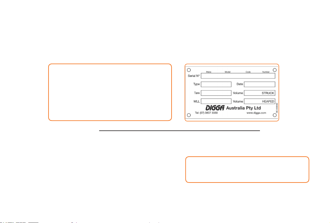
To facilitate warranty or service, record the model and serial number of your unit in the space provided on this page.
This information may be obtained from the identication plate located on the product.
IMPORTANT: WHEN SERVICING OR ASSEMBLING YOUR PRODUCT, REMEMBER TO USE ONLY GENUINE
DIGGA REPLACEMENT PARTS. SUBSTITUTE PARTS MAY NOT MEET THE STANDARDS REQUIRED FOR SAFE,
DEPENDABLE OPERATION. USE OF NON GENUINE DIGGA PARTS WILL VOID WARRANTY AND DIGGA WILL
ACCEPT NO LIABILITY WHAT SO EVER FOR CONSEQUENTIAL OR SPECIAL DAMAGES.

4PM-000052-A KUBOTA BUCKET NOVEMBER 2017
2 TABLE OF CONTENTS
1TO THE PURCHASER....................................................................... 3
2 TABLE OF CONTENTS..................................................................... 4
3 PREPARATION FOR USE................................................................. 5
4 INSTALLATION AND OPERATING INSTRUCTIONS........................ 6
5MAINTENANCE.................................................................................. 10
6 SAFETY STICKER LOCATION.......................................................... 12
7 SPARE PARTS................................................................................... 13
8TROUBLESHOOTING........................................................................ 16
9 SAFETY - GENERAL PRECAUTIONS.............................................. 18
10 SAFETY-WORKING WITH THE ATTACHMENT................................ 21
11 WARRANTY........................................................................................ 22
4 in 1 Kubota BX Bucket
MODELS COVERED IN THIS MANUAL
DIMENSIONS WEIGHT
Width (bucket cutting) 1225mm 48” BX Bucket 130Kg 286lbs
Width (overall) 1240mm 49” OPERATIONAL
Height 556mm 22” Holding Volume 0.1m3
Length 575mm 23”

5
To avoid any inconvenience before operation, please check that you have received the following items which
you may have ordered in your Kubota BX Bucket 3rd service kit
3 PREPARATION FOR USE
REF DESCRIPTION QTY
A 4 IN 1 KUBOTA BX BUCKET 1
B WIRING HARNESS 1
C ASSEMBLY HOSES 4
D HYDRAULIC VALVE KIT 1
ECONTROLLER HANDLE ASSEMBLY 1
F MOUNTING BRACKET 4
G BOLT 4
H NUT 4
A
B
C
D
E
F
H
G

6PM-000052-A KUBOTA BUCKET NOVEMBER 2017
1. Remove the shipping banding from around the Kubota BX Bucket and frame.
2. Remove any attachments from the front of the machine.
3. Ensure you have read the serial tag on the Kubota BX Bucket to obtain the max ows, pressure and load ratings. Ensure your
machine ow and pressure settings are aligned with the requirements of the Kubota BX Bucket.
NEVER EXCEED THE MAX FLOW AND PRESSURE RATINGS AS WARRANTY WILL BE VOID.
4. Following all standard safety practices and the instructions for installing an attachment in your machine operator’s manual, install
the Kubota BX Bucket onto your Machine.
5. Lower the unit to the ground and remove the key from the parent machine, following all procedures on the following page to t the
Kubota BX Bucket 3rd Service kit.
6. Carefully raise the loader and cycle the tilt cylinders to check clearances and to verify that all mounting procedures have been
successfully completed. The machine is now ready for use.
7. Check the cutting edges or teeth are not worn. Ensure all worn parts are replaced. Worn parts will become ineffective and severely
diminish the overall performance of the Kubota BX Bucket.
The DIGGA Kubota BX Bucket attaches to the main/lifting boom of your machine. Due to this arrangement, thorough knowledge of the ma-
chinery controls is necessary for machine operation. Read and understand your machine operator’s manual for information regarding machine
operation before attempting to use the Kubota BX Bucket. When a Kubota BX Bucket is purchased from Digga or a DIGGA Dealer/Distributor
the frame/attachment is matched for suitability and compatibility to the ow, pressures & load ratings of the original machine it was purchased
for. For tment of the Kubota BX Bucket to other machines you must rst contact your DIGGA dealer and receive written conrmation to ensure
you do not incorrectly t the Kubota BX Bucket to a machine with higher, pressure or rated load capacities than what the Kubota BX Bucket
was designed for. Warranty will be void if the Kubota BX Bucket is tted to an alternative machine without rst receiving written conrmation
from your DIGGA dealer. Exceeding the recommended max ow, pressure, or rated load capacity of the Kubota BX Bucket as stated on the
serial tag will void all warranty.
Check the work site and identify the extent of the work to be carried out and note any possible hazards or constraints. Underground cables,
services etc. Check with relevant government departments on the location of these before commencement of any work. Review the job at
hand and determine the Kubota BX Bucket is appropriate for the intended conditions.
4 INSTALLATION AND OPERATING INSTRUCTIONS
NOTE: IT IS IMPORTANT TO MAKE SURE THE LOCKING MECHANISM ON YOUR QUICK ATTACH IS ENGAGED,
THEREFORE LOCKING THE ATTACHMENT ONTO THE MACHINE.
INSTALLATION INSTRUCTIONS
IMPORTANT: BACK-DRAGGING MATERIAL OR PUSHING OR SCOOPING WITH THE FLOOR PARTIALLY OPEN
CAN RESULT IN DAMAGE TO PRODUCT AND WILL VOID ALL DIGGA WARRANTIES
7
4 INSTALLATION AND OPERATING INSTRUCTIONS
INSTALLATION OF KUBOTA BX BUCKET KIT FOR KUBOTA BX TRACTOR
This bucket and kit was developed to enable a Digga 4-in-1 bucket to be adapted to a Kubota BX mini tractor without the need of engaging hydraulics and auto
electrical specialists. The Owners Manual for this BX bucket kit does not cover the Kubota tractor and its controls and maintenance. Please refer to the Kubota
tractor owners manual for safe operation.
FITTING THE KUBOTA BX BUCKET 3rd Service KIT FOR KUBOTA BX TRACTOR
1. Connect the bucket to the machine. Ensure that all locking pins are secured and rmly locked in position
2. Remove the existing rubber handle from the control lever on the Kubota BX mini Tractor and replace with the joystick
controller (part no: EC-000093) supplied in the BX Kit. Tighten the two M6 grub screws on the joystick adapter to lock it
to the control stalk. Wrap the section of the harness to the control joystick with insulation tape (insulation tape not
supplied) (Fig:4)
3. Mount the hydraulic solenoid valve block and clamp it to the right hand inside of the lift arm directly above where the
rubber hoses connect to the steel lines as shown in the operating procedures.
4. Under the right hand side of the lift boom you will nd where the hydraulic hoses from the machine connect to the steel
tubes this is where the solenoid valve is to be mounted and connect into.
5. With the boom on the ground slowly release the pressure in the hydraulic lines disconnect the yellow and white hoses
from the steel lines here.
6. The yellow hose then connects to port 2 on solenoid valve. The white hose then connects to port 5 on solenoid valve.
7 Connect hose 1 from the kit to port 1 of valve block, then connect the end to the yellow steel tube on lift boom.
8. Connect hose 6 from the kit to port 6 on solenoid valve, then connect the end to the white steel line on the lift boom.
9.
Connect hose 3 from the kit to port 3 on solenoid valve, then connect the end to the upper tee on the Kubota BX bucket
.
10. Connect hose 4 from the kit to port 4 on solenoid valve, then connect the end to the lower tee on the Kubota BX bucket.
11. Ensure all hoses can’t fowl on anything and are not twisted then ensure all hose and ttings and the mounting of the
solenoid valve are tight.
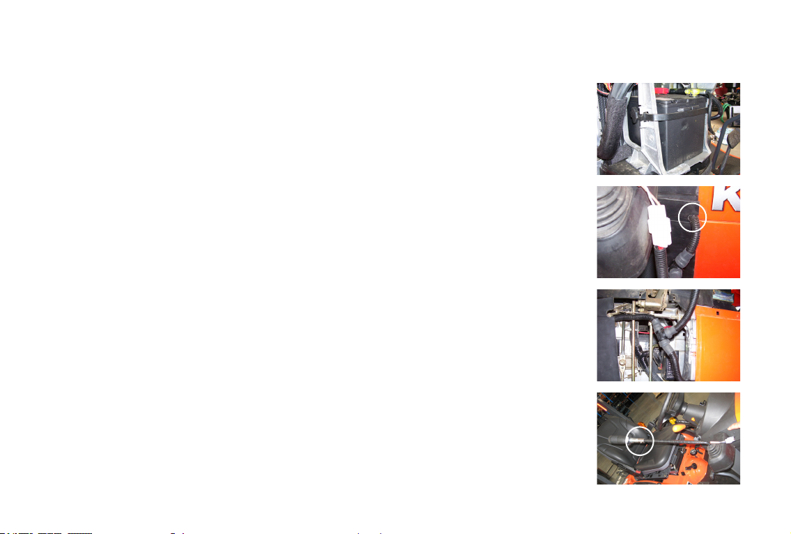
12. Refer to Kubota tractors manual and remove the battery cover from the tractor. Mark and drill a Ø 15mm hole and
notch it out in the position shown in Fig:2. Allowing the harness which runs to the joystick to easily slot into the battery
cover when the cover is installed or removed.
13. Run the wiring harness starting from the square black plug (Hirschmann plug) on the hydraulic solenoid valve and work
towards the battery. The harness exits/enters the engine bay adjacent to where the hydraulic quick couplers are
mounted and enters the battery compartment through the engine bay rewall and then connects to the battery. Attach
the harness using cable ties, after leaving them loose to determine that there is sufcient slack in the harness to allow
for the maximum movement of the boom.
14. Remove the battery and connect the positive and negative terminals of the harness to the corresponding battery
terminals NOTE: Ensure that the 10A inline fuse is accessible inside the battery compartment. (Fig:1)
15. Feed the section of the harness (which has the plastic 2-pin female connector) through the notch in the battery cover
and plug into the mating plug on the lead of the joystick controller Fig :2
16. Secure the harness in the battery compartment so that it can’t get pinched or jammed on any of the other controls.
Fig:3
FIG 1.
FIG 2.
FIG 3
FIG 4
8PM-000052-A KUBOTA BUCKET NOVEMBER 2017
4 INSTALLATION AND OPERATING INSTRUCTIONS
MOUNTING THE HYDRAULIC SOLENOID VALVE BLOCK
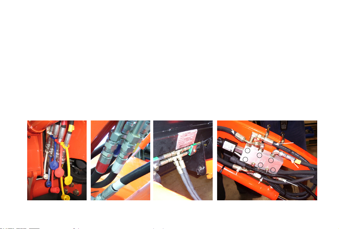
1. With bucket and arm at rest on the ground, disconnect the white and yellow quick release couplings (found under the right hand side
of the boom FIG 1).
2. Under the right hand side of the lift boom you will nd where the hydraulic hoses connect to steel tubes, this is where the soleniod
valve is to be mounted and connected into.
3. Then disconnect the yellow and white hoses from the steel lines (FIG 2)
4. Remove yellow hose and connect to Port 2 in valve block.
5. Remove white hose and connect to Port 5 in valve block
6. Connect Hose 3 to the upper tee on the Kubota BX Bucket to Port 3 on the soleniod valve block (FIG 3).
7. Connect Hose 4 to the lower tee on the Kubota BX Bucket to Port 4 on the soleniod valve block (FIG 3).
8. Connect Hose 1 to Port 1 in the valve block and the free end to the yellow steel tube (where the yellow hose previously was removed)
9. Connect Hose 6 to Port 6 in the valve block and the free end to the white steel tube (where the white hose previously was removed)
10. Mount the soleniod valve on the inside of the right hand arm where the yellow and white hose lengths permit, directly above the lift
cylinder on your machine
11. Use the 2 longer bolts to mount through the soleniod valve on the lower side of the lift boom and the two shorter bolts on the top side
of the boom.
FIG 1 FIG 2 FIG 3 FIG 4
HOSE 2
HOSE 5
HOSE 4
HOSE 3
HOSE 6
HOSE 1
1
2
3
6
54

9
OPERATING THE KUBOTA BX BUCKET USING THE JOYSTICK CONTROLLER
1. Start the Machine; adjust the engine speed above idle. Proceed to lift and crowd the bucket by
moving the joystick as follows.
2. Push the joystick forward the lower the boom down
3. Pull the joystick back towards operator to lift boom up
4. Pull the joystick left towards the operator to crowd the bucket back
5. Push the joystick to the right, away from operator to crowd the bucket forward.
OPENING AND CLOSING THE KUBOTA BX BUCKET USING THE JOYSTICK CONTROLLER
1. Push the joystick forward and depress the button (on top of the joystick) to close the bucket
2. Pull the joystick towards the operator and depress the button to open the bucket.
3. Pull the joystick left towards the operator to crowd the bucket back
4. Push the joystick to the right, away from operator to crowd the bucket forward.
STANDARD BUCKET OPERATION
1. Fully close the oor against the bulldozer weldment and this product can be used as a standard bucket.
2. When picking up small quantities of material, the oor should be opened. This product can be lowered to the ground so the material is
between the bulldozer weldment and the back edge of the oor. The oor can then be closed to pick up nearly all of the material.
3. When dumping into a truck or similar application, this product can dump at a greater height than a standard bucket by opening the oor to
release the material.
BULLDOZING OPERATION
1. With the oor open, tilt the bulldozer weldment forward so that the front cutting edge penetrates the desired depth into the soil or materials
being moved or levelled
BACK DRAGGING OPERATION
1. With the oor fully open, tilt the bulldozer weldment forward so that the back cutting edge of the oor is on the ground and the bulldozer
weldment is off the ground. The angle of the back cutting edge permits the operator to cut sod or other vegetation.
4 INSTALLATION AND OPERATING INSTRUCTIONS
OPERATING PROCEDURES
WARNING: DO NOT OPERATE THE KUBOTA BX BUCKET BEFORE READING THE INSTRUCTIONS BELOW
Boom Down
Boom Up
Crowd
Forward
Crowd
Back
Bucket Closed
(button depressed)
Bucket Open
(button depressed)
Crowd
Forward
Crowd
Back

10 PM-000052-A KUBOTA BUCKET NOVEMBER 2017
4 INSTALLATION AND OPERATING INSTRUCTIONS
GRAPPLE OPERATION
1. Open the oor sufciently to clear the object being lifted. Lower the bucket so that the object is between the bulldozer weldment and
the back cutting edge of the oor. Close the oor as completely as practical for the object being lifted and slowly begin lifting. If the
object is to unstable, lower the object back to the ground and repeat until the object remains stable during the entire process. Always
lower the object to a stable position before opening the oor.
REMOVAL AND STORAGE
1. Set the attachment on the ground and follow the standard shut down procedure in your loader operators manual.
2. With the loader OFF, disengage the attachment lock pins, release hydraulic pressure from the auxiliary hydraulic system and
disconnect the hydraulic couplers from the loader.
3. Start the machines engine and make sure that the lift arm is lowered and in contact with the loader frame.
4. Remove the 3 mount pivot pins starting with centre tilt pivot pin, then remove the 2 outer ones.
5. Remove and store the attachment/s in a dry and protected place. Leaving the attachment/s outside will materially shorten its life.
WHEN ATTACHMENTS NOT ON PARENT MACHINE
It is a requirement of the Australian Work place Health and Safety act 1995 that safe systems of work are employed when handling any at-
tachments. Complete compliance with Work place Health and Safety issues is compulsory and all due care and attention must be observed
at all times in any method of moving, transporting or storing any such device when not attached to a parent machine. We recommend
attachments are well secured when being moved or in transit and furthermore prior to moving, storing, loading/unloading or parking it is sug-
gested that the attachment is strapped/secured to a pallet or enclosed in a suitable container to minimise any movement or loss of the load
during such activity. NO responsibility for loss or damage to persons or property in any regard can be attributed to Digga.
TRANSPORTING THE ATTACHMENT
1. Follow all federal, state and local regulations when transporting the unit on public roads.
2. Use extra care when loading or unloading the machine onto a trailer or vehicle. Disconnect hydraulic couplers during transportation.
The key feature of your Digga Kubota BX Bucket is low maintenance. Unauthorised disassembly will void warranty
SAFETY FIRST!! READ AND UNDERSTAND THE SAFETY INSTRUCTIONS BEFORE BEGINNING ANY
MAINTENANCE
BEFORE FIRST USE
● Inspect the attachment for shipping damage. If damage does exist, do not operate until the damaged
parts have been replaced or repaired.
5 MAINTENANCE
11
● Make sure that all nuts and bolts are in place and properly tightened.
● Make sure that all other fasteners are in place and are performing their specied function.
● Make sure that all hydraulic ttings are tightened and that there are no leaks in any ttings or hoses.
● Make sure that all safety signs are in place, are clean, and are legible. (SEE THE SAFETY SIGN SECTION)
● Check for wear and tear on Pins, linkages, cutting edges
● Replace any damaged parts and excessively worn parts.
● Use only manufacturer recommended replacement parts. Other parts may be substandard in t and quality.
● Always wear safety goggles or glasses when inspecting equipment
BEFORE EACH USE
● Grease 6 ttings: one on each of the two pivot points for the oor and one
on each end of the two hydraulic cylinders.
Note: Some of the hydraulic cylinders have two grease ttings on the
cross tube end of the barrel section of the cylinder.
Only one of these two tting must be greased
EVERY 10 HOURS OF USE
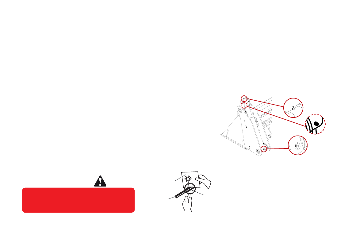
Escaping uid under pressure can have
sufcient force to penetrate the skin
causing serious personal injury. Fluid
escaping from a very small hole can be almost
invisible. Use a piece of cardboard or wood,
rather than hands to search for suspected
leaks. Keep unprotected body parts, such as
face, eyes, and arms as far away as
possible from a suspected leak. Flesh
injected with hydraulic uid may develop
gangrene or other permanent disabilities.
If injured by injected fluid, see a doctor at
once. If your doctor is not familiar with this
type of injury, ask him to research it
immediately to determine proper treatment.
WARNING! CARDBOARD
HYDRAULIC HOSE
OR FITTING
MAGNIFYING GLASS
Always wear safety goggles or glasses when inspecting equipment
5 MAINTENANCE
12 PM-000052-A KUBOTA BUCKET NOVEMBER 2017
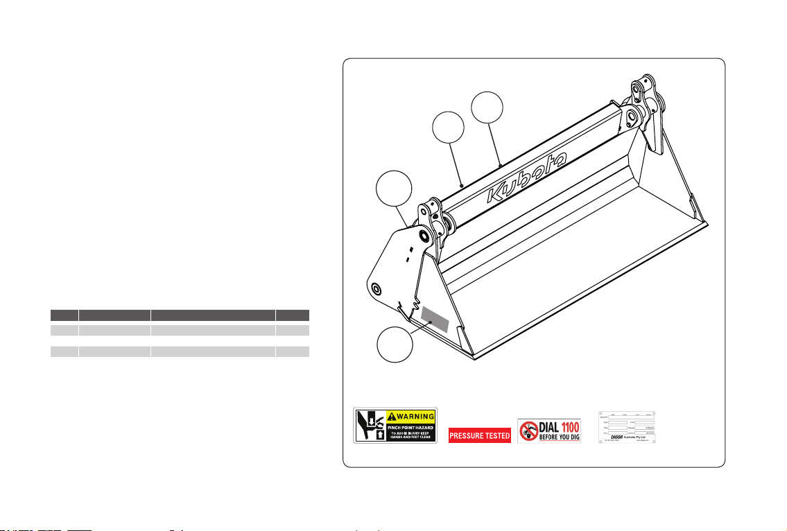
6 SAFETY - STICKER LOCATION
PLACEMENT OR REPLACEMENT OF SAFETY SIGNS
1. Clean the area of application with non-ammable
solvent, then wash the same area with soap and
water.
2. Allow the surface to fully dry.
3. Remove the backing from the safety sign, exposing
the adhesive surface.
4. Apply the safety sign to the position shown in the
diagram and smooth out any bubbles.
INSTRUCTIONS
● Keep all safety signs clean and legible.
● Replace all missing, illegible, or damaged safety signs.
● Replacement parts for parts with
safety signs attached must also have safety signs
attached.
● Safety signs are available from your dealer or from
Digga Australia.
1
2
34
ITEM 1 ITEM 2 ITEM 3
ITEM 4
NO. ORDER CODE DESCRIPTION QTY
1 DE-000129 Decal-Pinch Point 2
2 DE-000055 Decal-Pressure Tested 2
3 DE-000046 Decal-Dial Before You Dig 1
4 DE-000062 Serial Tag 1
13
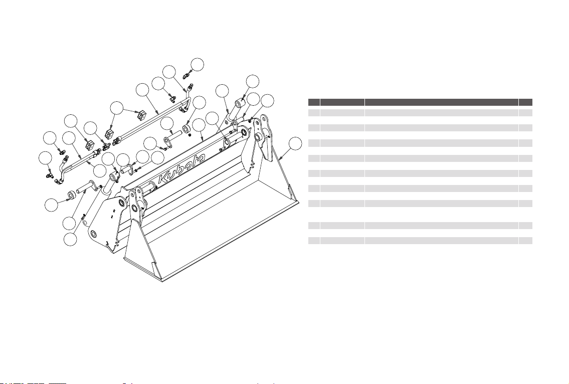
7 SPARE PARTS
NO ORDER CODE DESCRIPTION QTY
1 BU-001869 BUCKET- LIGHT MINI - FLOATING CYLINDER BUSH 2
2BU-000085 BUCKET - MINI - CLEVIS PIN BOTTOM 2
3 BU-000077 BUCKET - MINI - CLEVIS PIN CYLINDER 2
4 BU-000084 BUCKET - MINI - CLEVIS PIN MAIN 2
5 BU-001896 BUCKET - LIGHT MINI - BACK WELDMENT 1
6 BU-001942 BUCKET - LIGHT MINI - FLAT FLOOR WELDMENT 1
7 CY-000078 HYDR. CYLINDER-6” STROKE 1.5” SHAFT 2” BORE 2
8 FA-000093 NUT NYLOC 3/8” ZINC PLATED 6
9 FA-000149 BOLT HEX 3/8 X 1.1/4 G8 UNC ZINC PLATED 6
10 FA-000401 GREASE NIPPLE 6
11 HA-000031 S91 90DEG 9/16 MALE FITTING 4
12 HA-000375 STAUFF CLAMP 3
13 HA-000450 TEE - S19 JICM 2
14 HS-000521 KUBOTA BUCKET-RIGHT BOTTOM HOSE AS-
SEMBLY 1
15 HS-000522 KUBOTA BUCKET-RIGHT TOP HOSE ASSEMBLY 1
16 HS-000523 KUBOTA BUCKET-LEFT BOTTOM HOSE ASSEMBLY 1
17 HS-000524 KUBOTA BUCKET-LEFT TOP HOSE ASSEMBLY 1
Parts List
DESCRIPTION
PART NUMBER
QTY
ITEM
BUCKET - LIGHT MINI - FLOATING CYLINDER BUSH
BU-00186921
BUCKET - MINI - CLEVIS PIN BOTTOM - (OBSOLETE)
BU-00187022
BUCKET - MINI - CLEVIS PIN BOTTOM - (OBSOLETE)
BU-00187223
BUCKET - MINI - CLEVIS PIN MAIN - (OBSOLETE)
BU-0018742
4
BUCKET - LIGHT MINI - BACK WELDMENT - 1225mm
WIDE - KUBOTA LA243
BU-0018961
5
BUCKET - LIGHT MINI - FLAT FLOOR WELDMENT -
1225mm WIDE
BU-00194216
HYDRAULIC CYLINDER - 6 IN STROKE - 1.5 IN SHAFT
2.0 IN BORE - SUIT MINI BUCKETS - QMN
CY-000078
2
7
NUT NYLOC 3/8" ZINC PLATED
FA-00009368
BOLT HEX 3/8 x 1.1/4 G8 UNC ZINC PLATED
FA-00014969
GREASE NIPPLE 1/4" UNF
FA-000401610
S91 - 0909 90deg 9/16 MALE FITTING
HA-000031
4
11
STAUFF CLAMP 71440319/319
HA-000375312
TEE - S19-090909 - JICM JICM JICM
HA-000450213
HOSE ASSEMBLY - KUBOTA BUCKET- RIGHT BOTTOM
HOSE ASMMBLY
HS-000521
114
HOSE ASSEMBLY - KUBOTA BUCKET- RIGHT TOP
HOSE ASMMBLY
HS-000522
115
HOSE ASSEMBLY - KUBOTA BUCKET- LEFT BOTTOM
HOSE ASMMBLY
HS-000523
116
HOSE ASSEMBLY - KUBOTA BUCKET- RIGHT TOP
HOSE ASMMBLY
HS-000524
117
9
14
15
12
3
5
7
8
6
10
11
4
16
17
13
2
1
11
11
10
1
2
39
8
10
12
11
Bucket Spares

14 PM-000052-A KUBOTA BUCKET NOVEMBER 2017
7 SPARE PARTS
NO ORDER CODE DESCRIPTION QTY
1 FA-000067 BOLT HEX 5/16 X 3.1/2 G8 UNC ZINC PLATED 2
2 FA-000094 NUT NYLOC 5/16” UNC ZINC PLATED 4
3 FA-000492 BOLT HEX 5/16 X 4.1/2 G8 UNC ZINC PLATED 2
4 HA-000031 S91 90DEG MALE FITTING 4
5 HA-000070 S12 JICM UNOM LONG 90DEG ELBOW 2
6 HA-000161 DNDY-XXN SOLENIOD CARTRIDGE TO SUIT T-61A 1
7 HA-000165 SUN 12V SOLENOID 1
8 HA-000226 VALVE BLOCK - TO SUIT DNDY CARTRIDGE 1
9 HB-000018 HYDRAULIC MOUNTING BRACKET - KUBOTA LA 243 4
10 HS-000324 HOSE ASSEMBLY - KUBOTA BX - HOSE 1 - 797MM LONG 1
11 HS-000323 HOSE ASSEMBLY - KUBOTA BX - HOSE 3 AND 4 - 1374MM LONG 2
12 HS-002047 HOSE ASSEMBLY - KUBOTA BX - HOSE 6 - 900MM LONG 1
A
Parts List
DESCRIPTION
PART NUMBER
QTY
ITEM
BOLT HEX 5/16 x 3.1/2 G8 UNC ZINC PLATEDFA-00006721
NUT NYLOC 5/16" ZINC PLATEDFA-000094
4
2
BOLT HEX 5/16 x 4.1/2 G8 UNC ZINC PLATEDFA-00049223
S91 - 0909 90deg 9/16 MALE FITTINGHA-00003144
S12-0909 - JICM UNOM LONG 90DEG - ELBOWHA-00007025
DNDY-XXN SOLENOID CARTRIDGE TO SUIT T-61A
HA-00016116
770-212 SUN 12v SOLENOIDHA-00016517
VALVE BLOCK – MPI VALVE BLOCK TO SUIT DNDY
CARTRIDGE
HA-00022618
HYDRAULIC MOUNTING BRACKET - KUBOTA LA 243HB-00001849
HOSE ASSEMBLY - KUBOTA BX - HOSE 1HS-000320110
HOSE ASSEMBLY - KUBOTA BX - HOSE 3 AND 4HS-000323211
HOSE ASSEMBLY - KUBOTA BX - HOSE 6HS-000324
112
A
11
11
12
10
8
7
6
3
5
4
9
2
1
NOTE THIS HOSE MUST BOLT TO
THE BOTTOM TEE IN THE BUCKET
NOTE THIS HOSE MUST
BOLT TO THE TOP
TEE IN THE BUCKET
PART OF THE WHITE CIRCUIT
PART OF THE WHITE CIRCUIT
PART OF THE YELLOW CIRCUIT
PART OF THE
YELLOW CIRCUIT
5
4
Hydraulic Spares
NOTE THIS MUST BOLT TO THE
TOP TEE FITTING ON THE BACK
OF THE BUCKET
NOTE THIS HOSE MUST BOLT
TO THE BOTTOM TEE FITTING
ON THE BACK OF THE BUCKET
PART OF THE WHITE CIRCUIT
PART OF THE
YELLOW CIRCUIT

15
Parts List
ITEM QTY PART NUMBER DESCRIPTION
1 1 EC-000007 SINGLE SWITCH COMMAND LEVER (Cobra 622930) - For LA243 Ag Loader
2 1 EC-000035 ELECTRICAL COMPONENT - ASSEMBLY JOYSTICK ADAPTER
3 1 EC-000040 ELECTRICAL COMPONENT - KABOTA WIRE ASSEMBLY WITH DIN CONNECTOR
41EC-000047 ELECTRICAL COMPONENT - KABOTA WIRE ASSEMBLY WITH 10A INLINE FUSE
1
2
2
7 SPARE PARTS
NO ORDER CODE DESCRIPTION QTY
1 EC-000093 ASSEMBLY - CONTROLLER FOR BX LOADER 1
2 EC-000005 ELECTRICAL COMPONENT - KUBOTA WIRE HARNESS COMPLETE WITH DIN CONNECTOR & 10A INLINE FUSE 1
Electrical Spares

16 PM-000052-A KUBOTA BUCKET NOVEMBER 2017
8 TROUBLESHOOTING
KUBOTA BX BUCKET
TROUBLE POSSIBLE CAUSE REMEDY
Damage to Hydraulic
Cylinder Rod or Oil
Soil build up between cylinder and bucket Repair or replace cylinder.
Oil Leak Loose Fittings or Hoses Inspect and Repair or Replace.
Damage to Fittings or Hoses Inspect and Repair or Replace.
Damage to cylinder Inspect and Repair or Replace.
Damage to Bucket Abuse Contact your local Digga dealer.
Bucket not tting to parent machine correctly Contact your local Digga dealer.
Bucket Movement in reverse
to what is stated in operators
manual on page 9
Hose Nº 2 and Hose N° 5 may be connected to
the hydraulic valve in opposite to instructions.
See page 8, gure 4.
Hose N° 2 must (yellow band) must
connect to port N° 2 and Hose N°5
must connect to port N° 5 on the
hydraulic valve

17
18 PM-000052-A KUBOTA BUCKET NOVEMBER 2017
The DIGGA Kubota BX Bucket receives its power from the Parent Machine through the Auxiliary Valve circuit with Quick Release Couplers
normally located on the machine arms near the front. Attaching points on the Kubota BX Bucket are the same as the bucket attaching
points on your machine.
If you are in any doubt contact your nearest DIGGA Dealer for assistance.
SIGNAL WORDS: Note the use of signal words DANGER, WARNING, and CAUTION with the safety
messages. The appropriate signal word for each has been selected using the following guidelines:
DANGER: Indicates an imminently hazardous situation, which if not avoided, will result in death or serious injury. This signal word is to be
limited to the most extreme situations, typically for machine components which, for functional purposes, cannot be guarded.
WARNING: Indicates a potentially hazardous situation, which if not avoided, could result in death or serious injury, and includes hazards
that are exposed when guards are removed. It may also be used to alert against unsafe practices.
CAUTION: Indicates a potentially hazardous situation, which if not avoided, may result in minor or moderate injury. It may also be used to
alert against unsafe practices.
TAKE NOTE! THIS SAFETY ALERT SYMBOL FOUND THROUGHOUT THIS MANUAL IS USED TO CALL YOUR ATTENTION TO
INSTRUCTIONS INVOLVING YOUR PERSONAL SAFETY OR OTHERS. FAILURE TO FOLLOW THESE INSTRUCTIONS CAN
RESULT IN INJURY OR DEATH.
ATTENTION!
BECOME ALERT!
YOUR SAFETY IS INVOLVED!
THIS SYMBOL MEANS:
10 SAFETY PRECAUTIONS - GENERAL INFORMATION
This section is composed of various warnings and safety tips. Read and learn all the information in this section before you attempt to
use your attachment. Also read your machines owner’s manual before using your equipment. This knowledge will help you operate your
unit safely. Do not take this information lightly, it is presented for your benet and for the benet of others working around you. The
“Safety Alert Symbol” will be used throughout this manual. It will appear with the word DANGER, WARNING, or CAUTION, and a safety
message pertaining to the specic topic being covered. Take the time to read these messages as you come across them.
TO THE OPERATOR
The primary responsibility for safety with this equipment falls to the operator. Make sure that the equipment is operated only by trained
individuals that have read and understand this manual. Don’t hurry the learning process or take the unit for granted. It is the skill, care,
common sense, and good judgement of the operator that will determine how efciently and safely the job is performed. Know your equipment
before you start. Know its capabilities and how to operate all the controls. Visually inspect your equipment before you start, ensure correct
assembly and installation of the attachment and never operate equipment that is not in proper working order.Practice the operation of your
new attachment and become familiar with the controls and the way it handles on your machine.If there is any portion of this manual or function
you do not understand, contact your local authorized dealer or the manufacturer.

19
1. Never operate the attachment without rst reading and understanding the entire operator’s manual.
2. Do not paint over, remove or deface any safety signs or warning decals on your equipment.
3. Follow all safety decals. Keep them clean and replace them if they become worn, damaged or illegible.
4. Know your equipment inside and out. Know how to operate all controls and know emergency shut down procedures
5. Keep all stepping surfaces, pedals, and controls free from dirt, grease and oil. Keep equipment clean to help avoid injury from
slipping or a fall when getting on or off equipment
6. Operate the attachment only in daylight or sufcient articial light.
7. Always carry loads close to the ground. Do not step off machine platform with load raised.
8. Turn off engine before performing maintenance. All maintenance can be performed with the machine arms lowered. If lift arms
must be left raised for any reason, use a positive lift arm lock to secure the arms in place. Serious damage or personal injury could
result from lift arms accidentally lowering.
9. Reduce speed when driving over rough terrain, on a slope, or turning to avoid overturning the machine.
10. Check your work area and know where all utility lines are. Avoid hitting underground or overhead electrical wires, cables, pipes,
fence posts, gas lines, etc.
11. Never operate equipment while under the inuence of alcohol, prescription drugs or any other form of illegal recreational drugs
which could inhibit physical and/or mental capacity.
12. Do not exceed rated operating capacity, as machine may become unstable resulting in loss of control.
13. Always lower the loader arms or machine boom to the ground, shut off the engine and remove the key before getting off the unit.
14. Operators, helpers, and other personnel working near Kubota BX Bucket must wear steel-toe safety shoes, safety glasses, and hard
hats as a minimum. Hearing protection, respirators, and personnel protective clothing will be specied in the site-specic Health and
Safety Plan
15. Do not smoke when refuelling machine. Allow room in the gas tank for expansion. Wipe up any spilt fuel. Secure cap tightly when
done.
16. Be alert to others in the work area. Be sure others know when and where you will be working. Make sure no one is behind
equipment or within 6 metres of it operating.
17. Loose tting clothing, long hair, jewellery and equipment which might become entangled in moving equipment are prohibited while
working near Kubota BX Buckets.
18. Machines must be shut down and properly locked-out and tagged before repairs or maintenance is performed. Only properly trained
and qualied individuals are permitted to perform repairs and maintenance.
19. Site workers shall not be allowed on/in Kubota BX Bucket, while it is in operation or the equipment is being moved
20. Machinery must be shut down and the key removed before being left unattended.
21. Controls must be engaged slowly until hydraulic uids and the unit are up to operating temperature. This is critical during cold
weather. Impact or shock loading of the system is prohibited.
22. Kubota BX Buckets shall be used only for their designed intent and shall not be loaded beyond their rated capacity. Overloading or
exceeding the manufacturers specications will void all warranty.
10 SAFETY PRECAUTIONS - GENERAL INFORMATION

20 PM-000052-A KUBOTA BUCKET NOVEMBER 2017
10 SAFETY PRECAUTIONS - GENERAL INFORMATION
23. Only authorized, properly trained workers will be permitted to operate Kubota BX Buckets and Spreada Bars. All unnecessary
personnel will stand clear of Kubota BX Buckets and Spreada Bars or devices while they are in operation.
24. The operator shall verbally alert site workers and visually ensure all site workers are clear from dangerous parts of equipment
before starting or engaging equipment.
25. Kubota BX Bucket must be stationary before making adjustments to the equipment.
26. Kubota BX Buckets shall be cleaned only when the mechanism is in neutral and the Kubota BX Bucket stopped; long-handled
shovels shall be used to move cuttings from the bucket. Materials heavier than 10kgs must be moved mechanically or by using at
least two people.
27. During operation, weather conditions shall be monitored: operations shall cease during electrical storms or when electrical storms
are imminent.
WHEN MOUNTING THIS PRODUCT TO YOUR MACHINE
● Refer to the operator’s manuals of your machine, and your quick-attach for special or detailed mounting instructions.
● This product should t onto the quick-attach Frame or Hitch.
● If this product does not t properly, contact your Digga Dealer before operating.
● Never place any part of your body into the mounting plate, frame, hitch or loader holes. A slight movement of the power unit or this
product could cause serious injury.
● Where ‘Dead Man’ connections are connected or installed it is illegal to disengage, tamper with or remove them
BEFORE EACH USE, THOROUGHLY INSPECT THIS PRODUCT AND
● Make certain that all safety signs are in place and legible. Refer to the safety sign page in this manual for the placement of safety signs
for this product.
● Replace all damaged or excessively worn parts and hardware only with genuine Digga parts or with properly rated fasteners,
hydraulic hoses, or ttings.
● Make certain that all locking pins, latches, and connection devices are properly installed and secured.
● Make certain that all protective guards, canopies, doors, etc., are in place and secure.
WHEN ADJUSTING, SERVICING OR REPAIRING THIS PRODUCT
● Make no modications to your Kubota BX Bucket.
● When making repairs, use only genuine Digga parts for fasteners, hydraulic hoses, or hydraulic ttings, use only properly rated parts.
● Replacement parts, for parts with safety signs attached, must also have safety signs attached.
Table of contents
Other Digga Farm Equipment manuals


Popular Farm Equipment manuals by other brands


HE-VA
HE-VA Tip-Roller 4.5 m Operating Instructions, Spare parts list, Declaration of Conformity

Fema
Fema KMC 47 Series Operator's manual

Urban Burrows
Urban Burrows 3PUBU002FIR instruction manual

Farmet
Farmet DG3N operating manual

Erskine Attachments
Erskine Attachments 3S Operator's manual

Monosem
Monosem NG Plus Me 2017 manual


