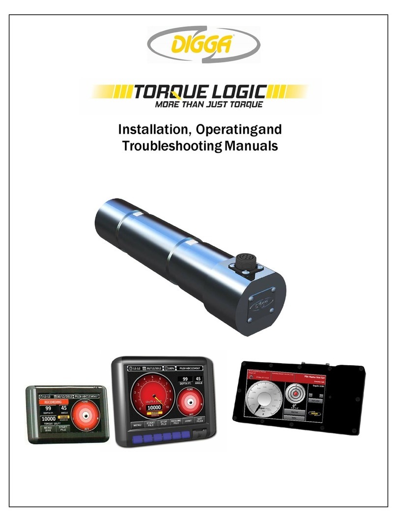
Digga TORQUE LOGIC User manual

1
PM-000121 Digga Torque Logic Installation Manual
MORE THAN JUST TORQUE
INSTALLATION
MANUAL
PM-000121

2PM-000121 Digga Torque Logic Installation Manual
TABLE OF CONTENTS
Tools Required for Installation.…………………………………………………..…...3
Personal Protective Equipment………………...………………………………….....3
Digga Torque Logic Installation Kit Contents…..…………………………………...3
Installation Directions…………………………………...…………………………......4
Removing OEM pin
Remove Knuckle/Wishbone
Inserting the Digga Torque Logic
Leveling
Marking Placement
Stopper…….………………………………..…………………………………………..5
Replacing Knuckle/Wishbone
Using The Pull Rod…..…………………………………….………………………......6
Pull Rod
Assembling Pull Rod
Tightening the nuts
End Cap………………………….………………………….……………………….......7
Assembling the End Cap
Securing the End Cap
Cabling………………………………..………………………………………………...8
Attaching the Extension Cable
Attaching the Pran Harness………………………………………………………......9
Attaching Pran Harness
Mounting Display Using Ram Mount Connections
Final Check
Warnings and Important Notes………………………………………………..…......9
General Safety Precautions……………………………...……………………….......10
Spare Parts……………………………...……………………….................................11

3
PM-000121 Digga Torque Logic Installation Manual
INSTALLATION INSTRUCTIONS
THE DIGGA TORQUE LOGIC HAS A COMPUTER PROCESSOR BOARD INSERTED
IN THE END OF THE PIN THESE ACTIONS WILL VOID THE WARRANTY!
TOOLS REQUIRED FOR INSTALLATION
• LEVEL
• ZIP TIES
• HEX SOCKET SET
• WELDER & RODS
• HAMMER WRENCH
• COMBINATION WRENCH
• STOPPER
• SHOP RAGS
PERSONAL PROTECTIVE EQUIPMENT
• SAFETY GLASSES
• COVERALLS
• HARD HAT
• STEEL CAP BOOTS
• GLOVES
• SAFETY GLASSES
TORQUE LOGIC INSTALLATION KIT
• DIGGA TORQUE LOGIC
• DOWEL & END CAP
• STEEL SOCKET CAP SCREW
• 2 WASHERS
• 3 NUTS
• THREADED ROD
CABLES
• MAIN CABLE JIB CABLE
• EXTENSION CABLE
• JUNCTION BOX
• 2 WASHERS
DIGGA TORQUE LOGIC DISPLAY
• 8.4” OR 4.3” DISPLAY
• PRAN HARNESS
• RAM MOUNT
• HITTING THE DIGGA TORQUE LOGO WITH A HAMMER OR ANY OTHER OBJECT.
• GROUNDING TO THE DIGGA TORQUE LOGO WHILE WELDING.
• USING EXCESSIVE HEAT ON OR CLOSE TO THE DIGGA TORQUE LOGIC
UNDO CABLE CONNECTIONS TO DIGGA TORQUE LOGIC
BEFORE WELDING IN ANY LOCATION ON PRIME MOVER.
WARNING

4PM-000121 Digga Torque Logic Installation Manual
DIRECTIONS
Once the OEM Pin is removed from the drive, remove the Knuckle/Wishbone.
Fasten the drive in a sturdy position and remove the OEM pin out from the top of the drive.
Insert the Digga Torque Logic into the holes of
the bails/ears to align pin placement.
A)
B) The connector on the Digga Torque
Logic must be facing up and parallel
with the drive. (Use a level to assure
correct placement)
The Digga Torque Logic has a at spot
on the bottom. Mark the placement of
the at area as this is where you will need
to secure the pin with a bolt on, or a bar
welded to the bushes/ears. This will keep
the Digga Torque Logic in position with the
drive to ensure accurate torque readings.
C)
1.
2.

5
PM-000121 Digga Torque Logic Installation Manual
Bolt or weld a stopper into place.
D)
Do not ground to the Digga Torque Logic. Tack the sides of the stopper, then remove
the Digga Torque Logic before solidly welding the stopper in place. Too much heat may
affect the “CPU” board.
WARNING
Replace the knuckle/wishbone and push the
Digga Torque Logic into the drive as far as it will
go, ensuring the connector is always facing up.
Do not hammer or tap the Digga Torque
Logic into place. This action will damage
the “CPU” and void the warranty.
WARNING
3.

6PM-000121 Digga Torque Logic Installation Manual
Assemble rod as shown.
B)
When placing a large heavy Digga Torque
Logic, it is advisable to use the threaded rod
and nuts (supplied) to draw the Digga Torque
Logic through the bails/ears.
Hold the 2nd nut tight while steadily turning the nut closest to
the end cap in a clockwise motion. This action will draw the
Digga Torque Logic through the bushes/ears. Be careful not
to apply to much pressure as this may damage the threaded
hole in the end of the Digga Torque Logic.
D)
Position the 2 end nuts on the rod and adjust according to
the amount of rod you will require to effectively pull the Digga
Torque Logic through the bails. Using 2 wrench’s tighten the
end nuts against one another.
C)
A)
NUT
NUT
THREADED ROD
NUT
FLAT WASHER
END CAP

7
PM-000121 Digga Torque Logic Installation Manual
END CAP
To apply the end cap to the Digga Torque
Logic, insert the provided dowel into the
unthreaded hole in the end of the End
Cap. Line up the dowel hole and the
threaded hole of the End Cap with the
dowel hole and the threaded hole on the
end of the Digga Torque Logic.
Secure the End Cap to the Digga Torque
Logic using steel socket cap screw and lock
washer (provided). It is recommended to use
BLUE LOCK TIGHT on the cap screw.
Recommended torque applied to the steel socket cap screw on the end cap.
1” bolt: 767 ft. lbs. 3/4” bolt: 317 ft. 1bs. 1/2” bolt: 93 ft. lbs.
A)
B)
SOCKET HEAD CAP SCREW
HIGH COLLAR LOCK WASHER
GROOVED DOWEL PIN
END CAP

8PM-000121 Digga Torque Logic Installation Manual
CABLING
Attach the main extension cable to the Digga
Torque Logic. Be sure to align the pins inside
the cable connector with the holes on the
Digga Torque Logic connection.
A Jib cable is recommended between the Digga Torque Logic and the disconnect of
your drive. Using a jib cable in this area will prevent damage to the main cable and is
easier to replace in the event it does get damaged.
Tuck and weave all cables in and behind the
hydraulic lines running along the boom, zip
tying into place as you go. At the end of the
boom run the main cable between the body of
the vehicle and the cab.
B)
A)
ZIP TIES
BOOM EXTENSION HARNESS
ADAPTER LEAD

9
PM-000121 Digga Torque Logic Installation Manual
CABLING CONTINUED
Attach the Pran Harness (provided) to the main cable. Make sure to
avoid pinch points when routing the Pran Harness inside the cab of
the machine.
Decide where to mount the Digga Torque Logic Display, which will
be convenient to the operator, close to a power source and avoid
excessive bumping or banging of the monitor.
Use the Ram Mount (provided) and attach it to the area inside the
cab that you have selected.
Tripple Suction Cup Ram Mount Single Suction Cup Ram Mount
E)
F)
G)
Attach the Pran Harness to the Digga Torque Logic Display, then the
Display to the Ram Mount. Ensure all connections are secure. (Note
the area at the back of the Digga Torque Logic Display screw hole
pattern to match the Ram Mount).
Do a nal check outside the cab to ensure the Digga Torque Logic
and end cap are secured properly, and all cable connections are
tight, with cabling free and clear of pinch points
Important Note: The Pran Harness is equipped with battery back up in the event of
accidental disconnection, however it is not recommended for steady use.
Protect the Digga Torque Logic Display by carefully following the
recommendations below.
When using the display always use the on/off switch on the harness to control power.
Never disconnect the power by pulling the plug from the power source. This can result
in corruption of data stored in your Display.
Do not tap on the screen of the Digga Torque Logic Display with any object other than
your nger. Hard or pointed objects may damage the screen.
Never use ngers to align hood to linkage when installing or removing the Digga
Torque Logic.
WARNING
D)
C)

10 PM-000121 Digga Torque Logic Installation Manual
GENERAL SAFETY PRECAUTIONS
• Always wear the proper personal protective equipment for the job you’re doing.
• When working on or near heavy equipment, approved hard hat and steel cap
boots are recommended.
• Lower the boom of the machine onto solid footing and stabilize before attempting to
remove the OEM.
• Turn off the power supply and apply the parking brake.
• Use your knees, not your back when picking up and placing heavy Digga Torque Logic
• Wear approved welding shield when welding stopper into place.
• Inspect all tools for weak points, wear and tear, and proper guards in place.
• Safety is the responsibility or the individual. Observe all safety procedures as outlined
by your employer.

11
PM-000121 Digga Torque Logic Installation Manual
SPARE PARTS
For further information on spare parts please contact your nearest Digga Dealer
AUSTRALIA
NORTH AMERICA
QLD
Head Office - Brisbane
4 Octal St, Yatala QLD 4207
Phone: (07) 3807 3330
Fax: (07) 3807 1499
DIGGA NORTH AMERICA
2325 Industrial Parkway SW
Dyersville, IA 52040
USA
Ph: +1 563 875 7915
Cell: +1 563 845 9177
www.diggausa.com

12 PM-000121 Digga Torque Logic Installation Manual
4 OCTAL STREET
YATALA QLD 4207
AUSTRALIA
PH: +61 (0) 7 3807 3330
MOBILE: +61 (0) 418 343 241
EMAIL: [email protected]
WWW.DIGGA.COM
DIGGA AUSTRALIA
2325 INDUSTRIAL PARKWAY SW
DYERSVILLE, IA 52040
USA
PH: +1 563 875 7915
CELL: +1 563 845 9177
EMAIL: [email protected]
WWW.DIGGAUSA.COM
DIGGA NORTH AMERICA
PM-000121
Other manuals for TORQUE LOGIC
1
Table of contents
Other Digga Measuring Instrument manuals
Popular Measuring Instrument manuals by other brands

3M
3M SpotOn 370 Operator's manual
Hanna Instruments
Hanna Instruments HI 84102 instruction manual
Crompton
Crompton Tyco Electronics SWITCHBOARD INTEGRA 1540 Installation and operating instructions
Greystone Energy Systems
Greystone Energy Systems CR3 Series installation instructions
CPN
CPN MC3 ELITE operating manual
Mahr
Mahr Millimar S 1840 operating instructions
