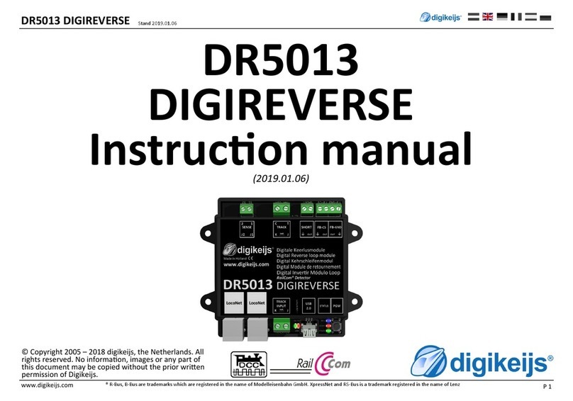
Digikeijs DR 4088LN Series User manual

DR4088LN-CS / GND / OPTO 2021-04-21
P 1
www.digikeijs.com ® R-Bus, B-Bus are trademarks which are registered in the name of Modelleisenbahn GmbH. XpressNet and RS-Bus is a trademark registered in the name of Lenz
DR 4088LN-xx
Instrucon manual
(2021-04-21)
© Copyright 2005 – 2018 digikeijs, the Netherlands. All
rights reserved. No informaon, images or any part of
this document may be copied without the prior wrien
permission of Digikeijs.

DR4088LN-CS / GND / OPTO 2021-04-21
P 2
www.digikeijs.com ® R-Bus, B-Bus are trademarks which are registered in the name of Modelleisenbahn GmbH. XpressNet and RS-Bus is a trademark registered in the name of Lenz
1 Index
1.0 General informaon 2
1.1 Index 2
1.2 Warranty and warranty condions 3
1.3 Legal informaon 3
2.0 Product overview
2.1 General product informaon 4
2.2 Technical Specicaons 4
2.3 Hardware Overview 5
3.0 Programming 6
3.1 Programming without further DR4088 on the S88
Connecng the DR4088LN-xx 6
3.1.1 Programming with the DR5000 6
3.1.2 Programming with any control panel
or App 7
3.2 Programming with addional DR4088 on the S88
Connecng the DR4088LN-xx 8
3.2.1 Programming with the DR5000 8
3.2.2 Programming with any control panel
or App 9
3.3 Reseng the DDR4088LN-xx 10
4.0 Connecon examples 10
4.1 Feedback modules DR4088LN-CS; 2-wire track 11
4.2 Feedback modules DR4088LN-CS and DR5033
Booster; 2-wire track 12
4.3 Feedback modules DR4088LN-OPTO; Hall sensors,
3-wire track 13
4.4 Feedback modules DR4088LN-OPTO; Hall sensors,
2-wire track 14
4.5 Feedback modules DR4088LN-GND
3-wire track 15
1 General Informaon

DR4088LN-CS / GND / OPTO 2021-04-21
P 3
www.digikeijs.com ® R-Bus, B-Bus are trademarks which are registered in the name of Modelleisenbahn GmbH. XpressNet and RS-Bus is a trademark registered in the name of Lenz
1.2 Warranty and warranty condions
All our products come with a 24-month manufacturer's warranty. Please read these operang instrucons carefully.
Damage to the product caused by non-compliance with these instrucons will invalidate the warranty.
ATTENTION: The warranty is void if the housing of the product is opened.
1.3 Legal informaon
Prinng errors and mistakes, technical or other changes as well as changes in the availability of individual products are expressly reserved.
Data and illustraons are non-binding. All changes to hardware, rmware and soware are reserved.
We reserve the right to change the design of the product, the soware and / or the rmware without prior noce.
Copyright
All Digikeijs operang instrucons and other wrien instrucons supplied and/or downloadable are protected by copyright.
Reproducon is not permied without the wrien permission of Digikeijs.

DR4088LN-CS / GND / OPTO 2021-04-21
P 4
www.digikeijs.com ® R-Bus, B-Bus are trademarks which are registered in the name of Modelleisenbahn GmbH. XpressNet and RS-Bus is a trademark registered in the name of Lenz
2.0 Product overview
2.1 General product informaon
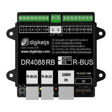
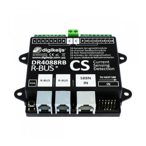
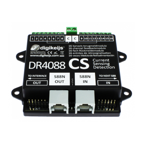
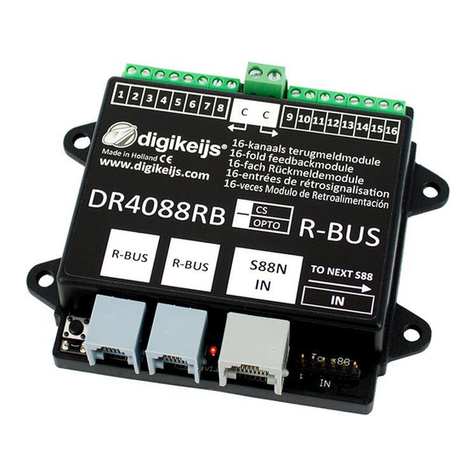
The DR4088LN-xx is a feedback module that can be connected to the control panel via LocoNet®.
The DR4088LN-xx has 16 feedback inputs.
The DR4088LN-xx is available as CS version (current sensor 2-wire track), OPTO version (connecon of reed contacts, 3-wire track signal to track ground) and
GND version (3-wire track).
2.2 Technical specicaons
The connecon terminals of the 16 feedback units are designed for a cross-secon of 0.5mm², the two terminals for "C" are designed for a cross-secon of
0.75mm².
Important! DR4088GND 3-wire operaon:
Due to the H-bridge (track output) in the DR50xx, feedback devices in the DR4088GND version must not be used against track ground, as
is usually the case with 3-wire tracks. This inevitably leads to the destrucon of the DR50xx.
If a 3-wire driver sll wants to drive with the DR50xx and report back against track ground, the DR4088OPTO
can be used.
Number of
inputs
Suitable
for
Minimum load for safe
reporng
Max. load per
contact Load
per contact
Max. load per contact
Load capacity
per contact for
max. 100 ms
Peak load for 8 feedbacks
at "C" total.
DR4088CS 2 x 8 2 conductors 2 mA 2 A 5 A 6 A an „C“
DR4088OPTO 2 x 8 3 conductors
when using the
DR50xx
- - -
DR4088GND 2 x 8 3 conductors

DR4088LN-CS / GND / OPTO 2021-04-21
P 5
www.digikeijs.com ® R-Bus, B-Bus are trademarks which are registered in the name of Modelleisenbahn GmbH. XpressNet and RS-Bus is a trademark registered in the name of Lenz
2.3 Hardware Overview
1Connecon feedback 1 to 8
2Common connecon "C" for the right or le
detector group.
3Connecon feedback 9 bis16
4Programming buon
5green LED
(ashes as soon as the power supply is available)
In addion, the LED signals by
dierent ashing cycles the two programming levels.
6LocoNet® Connector
7LocoNet® Connector
8red LED
(ashing during load or acvity at S88N connecon)
9S88N In Connector
10 S88 In Connector
123
5678910
4

DR4088LN-CS / GND / OPTO 2021-04-21
P 6
www.digikeijs.com ® R-Bus, B-Bus are trademarks which are registered in the name of Modelleisenbahn GmbH. XpressNet and RS-Bus is a trademark registered in the name of Lenz
3.0 Programming
First, something fundamental about LocoNet®:
• The LocoNet® is a universal bus system.
• The LocoNet® supports a maximum of 2048 feedback addresses.
• The addresses are always stored in the feedback module.
• The LocoNet® can be set up as a tree, star or bus (line) network. A combinaon of the individual topologies is permissible.
• Please note that a ring structure is not permied.
3.1 Programming DR4088LN-xx without further DR4088 on the S88N
DR DR4088LN-xx does not have LNCV's as known from other manufacturers. Therefore no LNCV's can be read out or changed.
The DR4088LN-xx must only be "told" the start address and the number of feedbacks via a switch command!
3.1.1 Programming with the DR5000
1. Connect the DR5000 to the DR4088LN-xx to be programmed.
2. (Normally it is not necessary to disconnect other feedback modules from LocoNet®.
3. Open the DR5000 Tool.
4. First the DR4088LN-xx must be assigned the start address.
5. Open the turnout control panel that contains the desired start address that the DR4088LN-xx is to receive.
6. Press the programming buon on the DR4088LN-xx. The green LED starts ashing to indicate that the DR4088LN-xx is in programming mode.
7. To assign the start address, switch the turnout address e.g. 1 once (i.e. only red or green!).
8. The green LED on the DR4088LN-xx now ashes in a dierent cycle to signal that the DR4088LN-xx next expects the number of feedback signals. The
number of feedback units is again sent to the DR4088LN-xx via a turnout command.
9. Normally, if no DR4088 (S88) is connected to the DR4088LN-xx, this is address 16.
10. In the DR5000 tool, call the turnout control panel which contains the address corresponding to the number of feedback signals.
11. Normally, this is address 16. Again, only red or green switching applies here.
12. The DR4088LN-xx automacally terminates the programming mode and is now programmed with the start address and the number of feedbacks.
.
Important! When using the LN or RB module, the ext88N IN number of 16 and 8 input modules must be set to 0 on the DR5000. This can be checked if in the feedback
monitor row 1 and row 9 are white with blue and not red!

DR4088LN-CS / GND / OPTO 2021-04-21
P 7
www.digikeijs.com ® R-Bus, B-Bus are trademarks which are registered in the name of Modelleisenbahn GmbH. XpressNet and RS-Bus is a trademark registered in the name of Lenz
3.1.2 Programming with any control panel or app.
1. Connect the central unit to the DR4088LN-xx to be programmed.
2. (Normally it is not necessary to disconnect other feedback modules from LocoNet®.
3. First the DR4088LN-xx must be assigned the start address.
4. Open the turnout control panel which contains the desired start address which the DR4088LN-xx is to receive.
5. Depending on which control panel, handset controller or app is used for programming, either the corresponding turnout or the corresponding turnout control
panel must be called at the control panel. With some App's a corresponding turnout with the desired address must be created.
6. Press the programming buon on the DR4088LN-xx. The green LED starts ashing to indicate that the DR4088LN-xx is in programming mode.
7. To assign the start address, switch the turnout address e.g. 1 once (i.e. only red or green!).
8. The green LED on the DR4088LN-xx now ashes in a dierent cycle and signals that the DR4088LN-xx next expects the number of feedback signals. The num-
ber of feedbacks is again sent to the DR4088LN-xx via a switch command.
9. Normally, if no DR4088 (S88) is connected to the DR4088LN-xx, this is address 16 .
10. At the central staon, at the handset controller or in the app, call up the turnout control panel which contains the address corresponding to the number of
feedback signals.
11. Normally this is the address 16. Again, only red or green switching applies.
12. The DR4088LN-xx automacally terminates the programming mode and is now programmed with the start address and the number of feedbacks..

DR4088LN-CS / GND / OPTO 2021-04-21
P 8
www.digikeijs.com ® R-Bus, B-Bus are trademarks which are registered in the name of Modelleisenbahn GmbH. XpressNet and RS-Bus is a trademark registered in the name of Lenz
3.2 Programming DR4088LN-xx with further DR4088 at the S88(N) connecon
3.2.1 Programming with the DR5000
1. connect the DR5000 to the DR4088LN-xx to be programmed
(normally it is not necessary to disconnect other feedback modules from the LocoNet®)
2. open the DR5000 tool.
3. First, the DR4088LN-xx must be assigned the start address.
Open the turnout control panel that contains the desired start address that the DR4088LN-xx is to receive.
4. Press the programming button on the DR4088LN-xx. The green LED starts flashing to indicate that the DR4088LN-xx is in programming mode.
5. to assign the start address switch the turnout address e.g. 1 once (so only red or green!).
6. The green LED on the DR4088LN-xx now flashes in a different clock pulse to indicate that the DR4088LN-xx is expecting the number of feedbacks next.
The number of feedback signals is again sent to the DR4088LN-xx via a switch command.
Example:
DR4088LN-xx DR4088
Start address 1 Number of feedback units 32 The switch address 32 must be sent here.
DR4088LN-xx 2x DR4088S
tart address 1 Number of feedback units 48 The switch address 48 must be sent here.
R4088LN-xx 3x DR4088
Start address 1 Number of feedback sensors 64 The switch address 64 must be sent here
.etc.
7. In the DR5000 tool, call the turnout control panel containing the address corresponding to the number of feedback signals. Again, only red or green
switching applies.The DR4088LN-xx automatically terminates the programming mode and is now programmed with the start address and the number
of feedbacks.
Aenon! At the S88 connecon of the DR4088LN-xx A maximum of 15 DR4088 can be connected to the S88 connecon of the DR4088LN-xx. This results
in a maximum number of 256 feedback contacts that a DDR4088LN-xx can manage.
Example: DR4088LN-xx 15x DR4088 Start address 1 Occupied feedback device Address range 1 - 256

DR4088LN-CS / GND / OPTO 2021-04-21
P 9
www.digikeijs.com ® R-Bus, B-Bus are trademarks which are registered in the name of Modelleisenbahn GmbH. XpressNet and RS-Bus is a trademark registered in the name of Lenz
3.2.2 Programming with any control panel or app.
1. Connect the central unit to the DR4088LN-xx to be programmed
(normally it is not necessary to disconnect other feedback modules from the LocoNet®).
2. First, the DR4088LN-xx must be assigned the start address.
Open the turnout control panel that contains the desired start address that the DR4088LN-xx is to receive. Depending on which control panel, handset or app
is used for programming, either the corresponding turnout or the corresponding turnout control panel must be called at the control panel. With some App's a
corresponding switch with the desired address must be created.
3. Press the programming button on the DR4088LN-xx. The green LED starts flashing to indicate that the DR4088LN-xx is in programming mode.
4. To assign the start address switch the switch address e.g. 1 once (so only red or green!).
5. The green LED on the DR4088LN-xx now flashes in a different clock pulse and signals that the DR4088LN-xx next expects the number of feedbacks. The num-
ber of feedback signals is again sent to the DR4088LN-xx via a switch command.
Example:
DR4088LN-xx DR4088
Start address 1 Number of feedback units 32 The switch address 32 must be sent here.
DR4088LN-xx 2x DR4088
Start address 1 Number of feedback units 48The The switch address 48 must be sent here.
DR4088LN-xx 3x DR4088
Start address 1 Number of feedback sensors 64 The switch address 64 must be sent here.
etc.
6. At the control panel, at the handset controller or in the app, call up the turnout control panel which contains the address corresponding to the number of
feedbacks.
With some App's a corresponding switch with the desired address must be created. Again, only red or green switching applies.
7. The DR4088LN-xx automatically terminates the programming mode and is now programmed with the start address and the number of feedback devices.
Aenon! At the S88 connecon of the DR4088LN-xx A maximum of 15 DR4088 can be connected to the S88 connecon of the DR4088LN-xx. This results
in a maximum number of 256 feedback contacts that a DDR4088LN-xx can manage.
Example: DR4088LN-xx 15x DR4088 Start address 1 Occupied feedback device Address range 1 - 256

DR4088LN-CS / GND / OPTO 2021-04-21
P 10
www.digikeijs.com ® R-Bus, B-Bus are trademarks which are registered in the name of Modelleisenbahn GmbH. XpressNet and RS-Bus is a trademark registered in the name of Lenz
4.0 Connecon examples
In this chapter you will nd some connecon examples for the DR4088LN-xx. Please note that we are not able to show all possibilies that exist.
3.3 Reset DR4088LN-xx
Important! The DR4088LN-xx has no funcon to reset to factory sengs!
The DR4088LN-xx has no funcon for reseng to factory sengs! This is also not necessary because no other funcons can be set in the
DR4088LN-xx except the start address and the number of response addresses.
To reset the response address back to the basic seng 1, it is sucient to send it again to the DR4088 LN-xx as described above. In the second
step, the number of feedbacks must be reset to 16 as described above. Further steps are not necessary.
Important! DR4088LN-GND 3-wire operaon DR4088LN-GND 3-wire operaon:
Due to the H-bridge (track output) in the DR50xx, feedback devices in the DR4088LN-GND version must not be used against track ground, as is
usually the case with 3-wire tracks. This inevitably leads to the destrucon of the DR50xx.
If a 3-wire driver sll wants to drive with the DR5000 and report back against track ground, the DR4088OPTO
can be used.

DR4088LN-CS / GND / OPTO 2021-04-21
P 11
www.digikeijs.com ® R-Bus, B-Bus are trademarks which are registered in the name of Modelleisenbahn GmbH. XpressNet and RS-Bus is a trademark registered in the name of Lenz
4.1 Feedback modules DR4088LN-CS; 2-wire track
® R-Bus, B-Bus are trademarks which are registered in the name of Modelleisenbahn GmbH. XpressNet and RS-Bus is a trademark registered in the name of Lenz
DR5000 in conjuncon with LocoNet® feedback modules (DR4088LN-CS)
In this example the LocoNet® modules DR4088LN-CS (current sensor principle) are used.
These feedback modules are connected to the DR5000 via LocoNet®. A maximum of 128
modules with 16 inputs each can be connected to the LocoNet T socket of the central unit.
A total of 2048 feedback modules are thus possible.
All other connected feedback modules which are connected via ext88N or R-Bus® must be
disconnected from these 2048 feedback modules.
Please note that a DDR4088LN-xx can manage a maximum of 15 DR4088.
DR4088LN CS
Other LocoNet®
components
More S88
feedback unit

DR4088LN-CS / GND / OPTO 2021-04-21
P 12
www.digikeijs.com ® R-Bus, B-Bus are trademarks which are registered in the name of Modelleisenbahn GmbH. XpressNet and RS-Bus is a trademark registered in the name of Lenz
4.2 Feedback modules DR4088LN-CS and DR5033 Booster; 2-wire track
® R-Bus, B-Bus are trademarks which are registered in the name of Modelleisenbahn GmbH. XpressNet and RS-Bus is a trademark registered in the name of Lenz
Other Loconet®
components
Both sides
track isolaon

DR4088LN-CS / GND / OPTO 2021-04-21
P 13
www.digikeijs.com ® R-Bus, B-Bus are trademarks which are registered in the name of Modelleisenbahn GmbH. XpressNet and RS-Bus is a trademark registered in the name of Lenz
Power supply
4.3 Feedback modules DR4088LN-OPTO; Hall sensors, 3-wire track
Light barrier, Hall sensors or
the like
(posive switching PNP)
5V-20V
DC/AC
Feedback "Track mass" switch track reed contact
DR4088LN-OPTO
More DR4088LN-xx
feedback unit

DR4088LN-CS / GND / OPTO 2021-04-21
P 14
www.digikeijs.com ® R-Bus, B-Bus are trademarks which are registered in the name of Modelleisenbahn GmbH. XpressNet and RS-Bus is a trademark registered in the name of Lenz
4.4 Feedback modules DR4088LN-OPTO; switch track, 2-wire track
switch track Light barrier, Hall sensors or
the like
(posive switching PNP)
Power supply
5V-20V
DC/AC
reed contact push buon switch
DR4088LN-OPTO
More DR4088LN-xx
feedback unit

DR4088LN-CS / GND / OPTO 2021-04-21
P 15
www.digikeijs.com ® R-Bus, B-Bus are trademarks which are registered in the name of Modelleisenbahn GmbH. XpressNet and RS-Bus is a trademark registered in the name of Lenz
4.5 Feedback modules DR4088LN-GND;switches, buons, reed contacts
push buon switch reed contact
DR4088LN-GND
More DR4088LN-xx
feedback unit
Feedback "Track mass" switch track reed contact
Track Out
Central
LocoNet®
Central
Important! DR4088LN-GND 3-wire operaon DR4088LN-GND 3-wire operaon:
Due to the H-bridge (track output) in the DR50xx, feedback devices in the DR4088LN-GND version must not be used against track ground,
as is usually the case with 3-wire tracks. This inevitably leads to the destrucon of the DR50xx.
If a 3-wire driver sll wants to drive with the DR5000 and report back against track ground, the DR4088OPTO
can be used.
This manual suits for next models
3
Table of contents
Other Digikeijs Control Unit manuals
Popular Control Unit manuals by other brands
GEM
GEM 520 Installation, operating and maintenance instructions
Unitronics
Unitronics Vision OPLC V130 installation guide
RectorSeal
RectorSeal CLEAN CHECK installation instructions

Kohler
Kohler K-2976-KS Installation and care guide

Nordson EFD
Nordson EFD 750V Maintenance & Parts Guide

SGM LEKTRA
SGM LEKTRA VLW602 Technical documentation

DoorHan
DoorHan CV01 owner's manual

Viessmann
Viessmann Vitotronic 100 KW10B Operating instructions and user's information manual
Regul' Electronique
Regul' Electronique Bulleur Installing instructions

LG
LG LGXXXQ1CK-A5 installation manual
Festo
Festo SLG-Z Series operating instructions
IBC
IBC P-270 installation instructions
