IBC P-270 User manual

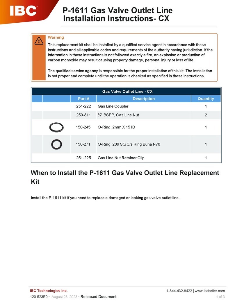
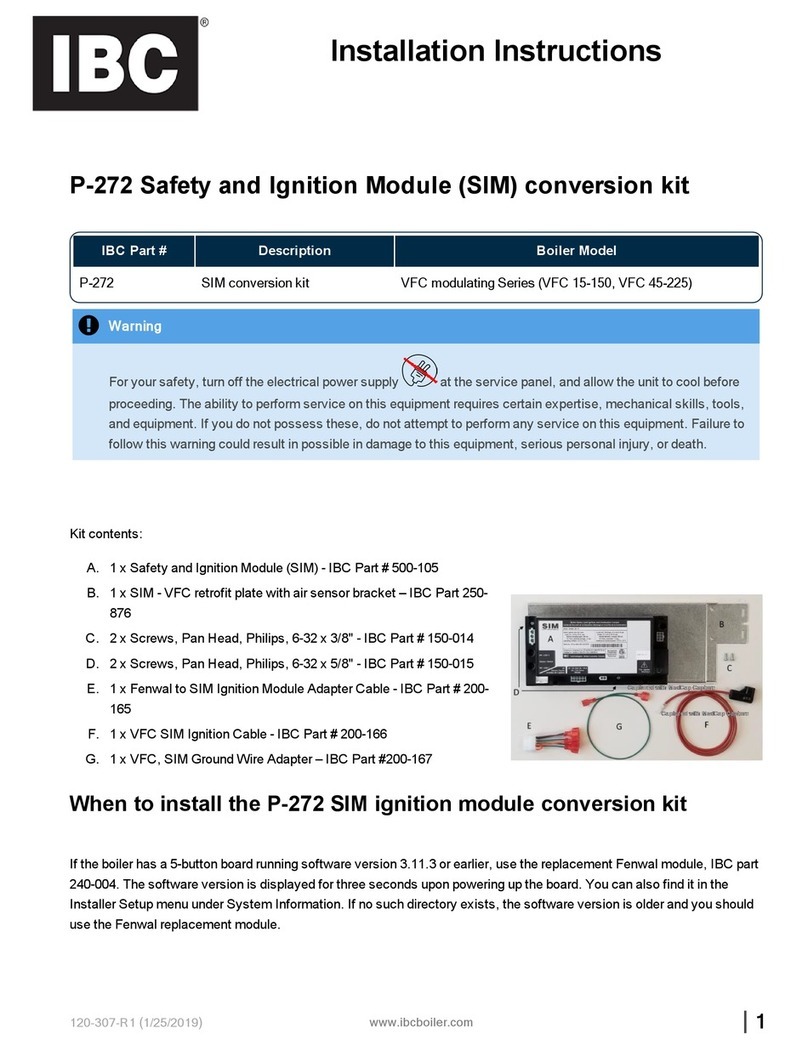
P-270 Safety Ignition Module (SIM) replacement kit
If the boiler has a 5-button board running software version 3.11.3 or earlier, use the replacement Fenwal module,
IBC part 240-004. The software version is displayed for three seconds upon powering up the board. You can also
find it in the Installer Setup menu under System Information. If no such directory exists, the software version is
older and you should use the Fenwal replacement module.
IBC Part # Description Boiler Model
P-270 Safety Ignition Module (SIM) SL Series 'G1' (SL 20-115, SL 28-160, SL 30-175, SL
35-199, SL 45-260, and SL 80-399), SL Series G2, SL
40-399 G3, SL 26-260 G3
Warning
This kit must be installed by a qualified service agency in accordance with the manufacturer’s instructions
and all applicable codes and requirements of the authority having jurisdiction. If the information in these
instructions is not followed exactly, a fire, an explosion or production of carbon monoxide may result
causing property damage, personal injury or loss of life. The qualified service agency is responsible for the
proper installation of this kit.
Note
For increased reliability, we recommend that you replace the electrode/flame sensing rod when you
replace the SIM (purchased separately). It is possible to reuse ignitors with low running hours.
Kit contents:
A. SIM module (backwards compatible mode) - # 500-105
B. 2 x screws - 6-32 x 5/8" - #150-015
C. SIM adapter cable # 200-165
D. SIM Ignitor cable # 200-154
E. USB stick with software version 1.03.3 or later- # 900-009
Installation Instructions
120-275-R5 - 1/25/2019 |1

2|
Replacing a SIM in the SL 'G1' and G2 series boilers
The supplied USB contains the latest software that we recommend using to update - although not essential
- the above models with the latest features. Note that you cannot update the older 5-button controller boards
with a USB. For additional information on the ignition system, its normal operation, and troubleshooting,
refer to the boiler’s Installation and Operation manual.
Figure 1 SIM connections - SL G1 and G2 series boilers
Boilers with a 5-button controller running software version 3.11.4 can use this kit. All 5-button boards
running version 3.11.3 or earlier should use the replacement Fenwal Ignition module, IBC part 240-004. The
software version is displayed for three seconds upon powering up the board. You can also find it in the
Installer Setup menu under System Information. If no such directory exists, the software version is older
and you should use the Fenwal replacement module.
The P-270 SIM kit replaces the Fenwal or Capable Controls ignition module for all IBC SL series 'G1' (SL
20-115, SL 28-160, SL 30-175, SL 35-199, SL 45-260, and SL 80-399) and G2-series boilers. Yo do not need
to use the supplied USB software update for these models. However, the update provides the latest
features and improvements. For information on how to perform a software update, see Software update.
Note that you cannot update the 5-button control boards with a USB.
1. Disconnect the power to the boiler and close the gas shut-off valve.
This SIM kit can replace an IBC Fenwal Ignition module, a Capable Controls module, or an existing
SIM.
If replacing an existing SIM, all the module’s connector plugs, except the ignition lead, have
retaining clips.
2. Note the position of the retaining clips for each plug.
To unplug the connectors, you must press down on the retaining clips and then properly release
them.

120-275-R5 -1/25/2019 |3
3. Unplug the connectors from the module. If replacing a Fenwal or Capable Controls Ignition module,
disconnect the wires one by one. If necessary, use needle-nose pliers to grip the wire terminals.
4. Check that the wire connections are still solid and secure.
5. To remove the existing module, hold it firmly in place as you unscrew the two mounting screws. Keep
the screws.
6. Position the new module, so that the mounting holes align.
7. Insert the screws, and lightly tighten to secure the module in place. Do not over-tighten.
8. If replacing a Fenwal or Capable Controls ignition module, attach the SIM adapter cable provided to
transition from the boiler wiring harness. The wiring connections are color-coded. For example, from the
gas valve the brown and blue wires connect to the brown and blue plugs on the SIM adapter cable. If
wires are not color-coded, use any plug, for example, for multiple green grounding wires.
9. Replace the original ignitor cable with the SIM ignitor cable provided, and run it to the ignitor tab on the
SIM (see image above).
10. Leaving the gas off, restore power to the boiler.
11. If the ignitor was replaced, pressurize the combustion chamber for a leak test around the ignitor gasket
with an approved leak test solution:
Remove any call for heat.
From the Main Menu, go to Diagnostics >Fan Operation.
Press the Vent Test On/Off button to drive the fan into high speed.
When complete, press On/Off again, and wipe off the excess solution.
12. Leaving the gas off, initiate a call for heat. Look through the sight glass to see that the spark is present
during the ignition trial.
13. If the spark looks bright and stable, turn on the gas and allow the boiler to go through another trial for
ignition. It should light off smoothly and quietly.
Replacing a SIM in the SL G3 series boilers
For the controller to recognize the new SIM, the boiler requires software version 1.03.3 or later.
Tip: To check the boiler controller's software version, in the Main Menu, select Diagnostics>Boiler
Information>Software Release. If your boiler requires a software update, see Downloading software
from the USB to the touchscreen controller on page 5.

4|
Figure 2 SIM connections - SL 26-260 G3, SL 40-399 G3 series boilers
1. Disconnect the power to the boiler and close the gas shut-off valve.
All the module’s connector plugs, except the ignition lead, have retaining clips.
2. Note the position of the retaining clips for each plug. To unplug the connectors, you must press
down on the retaining clips and then properly release them.
3. Unplug all the connectors from the module.
4. Check that the wire connections are still solid and secure.
5. To remove the existing module, hold it firmly in place as you unscrew the two mounting screws.
Keep the screws.
6. Position the new module, so that the mounting holes align.
7. Insert the screws and lightly tighten to secure the module in place.
8. Plug the connectors into their respective sockets (see image above), ensuring that the retaining
clips click into place properly. Each wire connector plug should fit snugly into a socket.
9. Plug connectors into their respective sockets, ensuring that the retaining clips click into place
properly.
Each wiring connector should fit snugly into a socket.
Note that the Ignition Module adapter cable part # 200-115 (included in this kit) is not used on G3
Series boilers, and can be discarded. Similarly, a G3 will already have a SIM Ignition Cable 200-154,
so the ignition cable provided with this kit can be set aside as a spare part.
10. Leaving the gas off, restore power to the boiler.
11. If the ignitor was replaced, pressurize the combustion chamber for a leak test around the ignitor
gasket with an approved leak test solution. To do this:
Remove any call for heat.
From the Main Menu, go to Diagnostics >Fan Operation.
Press the Vent Test On/Off button to drive the fan into high speed.
When complete, press On/Off again, and wipe off the excess solution.

120-275-R5 -1/25/2019 |5
12. Leaving the gas off, initiate a call for heat.
13. Look through the sight glass to check that a spark is present during the ignition trial.
14. If the spark looks bright and stable, turn on the gas and allow the boiler to go through another trial for
ignition. It should light off smoothly and quietly.
Downloading software from the USB to the touchscreen
controller
1. At the boiler, remove active calls for heat. The home screen should show a Standby status.
2. Carefully insert the USB stick into one of the ports on the left-hand side of the controller.
3. On the controller screen, tap Main Menu>Diagnostics>Advanced Diagnostics>Software Update.
4. Select the USB.
If you do not get a response, select Cancel and try again.
The controller checks if a software update is required. If required, the system prompts you for
permission to proceed.
5. Select Yes and OK.
If you see a message "Could not mount flash device", select Cancel and try again. The controller
automatically restarts after loading the update, and the process takes a few minutes.
6. To check that the controller has the latest software release, go to Main Menu>Diagnostics>Boiler
Information>Software Release.
Table of contents
Other IBC Control Unit manuals
Popular Control Unit manuals by other brands

Honeywell
Honeywell 804973 Installation instruction

Sierra Wireless
Sierra Wireless AirPrime SL808 Series Migration guide

O&O
O&O LOG-BC Installation and operation manual

ITT
ITT Flygt 4901 Installation, Care and Maintenance

AVK
AVK 41 Series Installation, operation and maintenance manual

ADTRAN
ADTRAN Job Aid+ 1442707G3 manual