digirails DR4024 DIGISERVO User manual
DR4024 DIGISERVO (v1.31)
Pagina / page / Seite / page 1
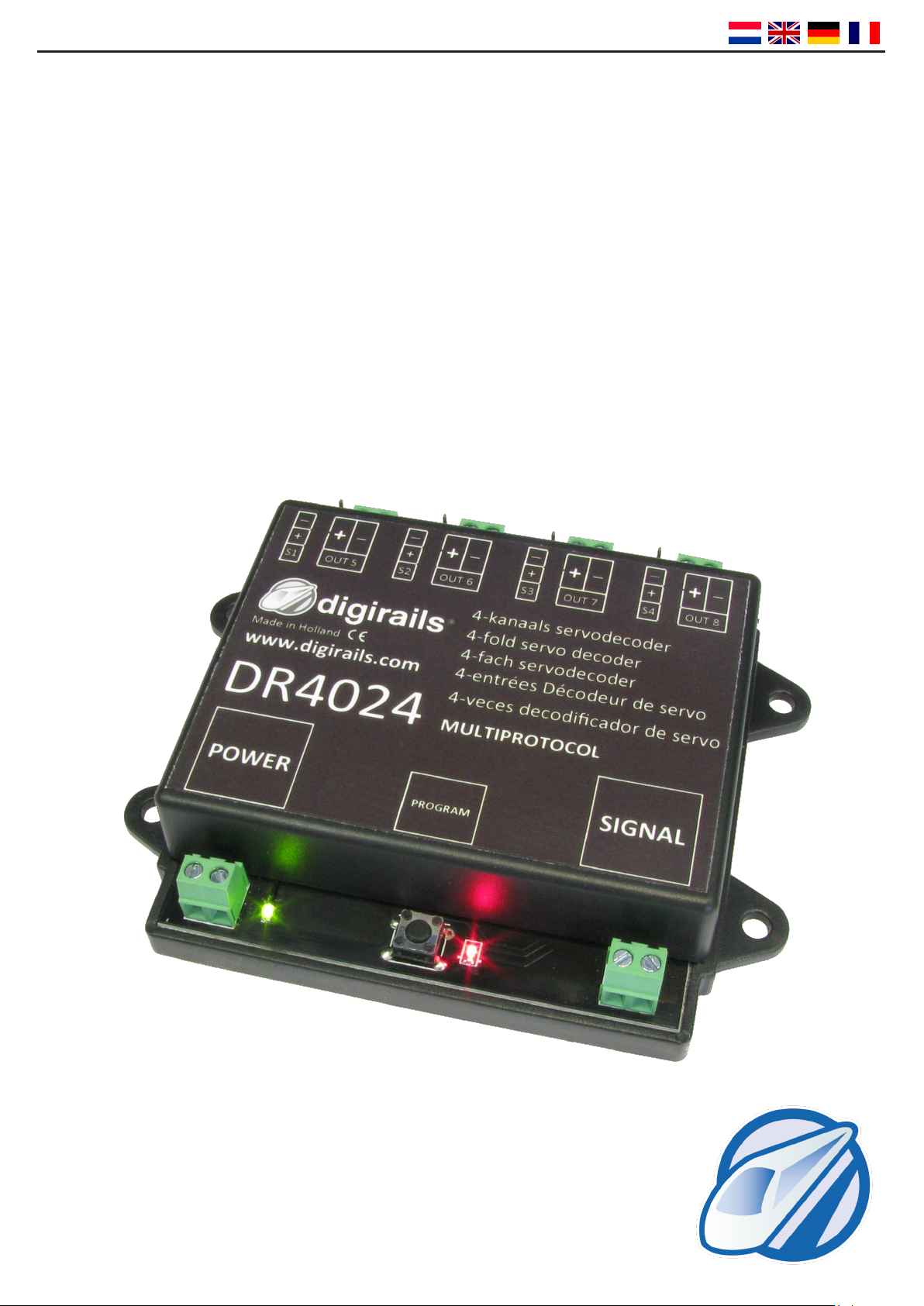
DR4024
DIGISERVO
HANDLEIDING / MANUAL
BEDIENUNGSANLEITUNG / MANUEL
V1.31 (08-2013)
© Copyright 2005 – 2013 digirails, the Netherlands. All rights re-
served. No informaon, images or any part of this document may
be copied without the prior wrien permission.
DR4024 DIGISERVO (v1.31)
Pagina / page / Seite / page 2
Nederlandse Handleiding
Pagina 3 - Specicaes
Pagina 4 - Uitgebreide beschrijving
Pagina 5 - Adresseren en reset
Pagina 6 - Servo posies instellen
Pagina 7 - CV’s wijzigen
Pagina 8 - CV Lijst
Pagina 10 - Funcemappen
Pagina 11 - Presets
English manual
Page 3 - Specicaons
Page 12 - Detailed descripon
Page 13 - Seng addresses and reset
Page 14 - Seng up servo posions
Page 15 - Changing CVs
Page 16 - CV list
Page 18 - Funcon mapping
Page 19 - Presets
Bedienungsanleitung Deutsch
Seite 3 - Technische Daten
Seite 20 - Ausführliche Beschreibung
Seite 21 - Schaltadressen und Reset
Seite 22 - Servo Posionen einstellen
Seite 23 - CVs verändern
Seite 24 - CV Liste
Seite 26 - Funkonsmapping
Seite 27 - Voreinstellungen
Manuel français
Page 03 - Spécicaons
Page 28 - Descripon détaillée
Page 29 -
Réglage des adresses et du edémarrage
Page 30 - Mise en place des positions de servo
Page 31 - Changement des CVs
Page 32 - Liste de CV
Page 34 - Mappage de foncons
Page 35 - Préréglages
Compabiliteit met verschillende centrales
Type Centrale / Control unit type
Zentralentyp/ Centrale de commande
Protocol / Protocol
Protokoll / Protocole
Schakelen
Switching
Schalten
Commutateur
Programmeerspoor
Programming track
Programmiergleis
Volet de programmaon
POM
Intellibox DCC / Motorola VVV
Intellibox Basic DCC / Motorola VVV
Intellibox II DCC / Motorola VVV
Marklin 6021 Motorola VXX
Marklin CS1 / CS2 Motorola VVV
ROCO/Fleischmann Mulmaus DCC VXV
ROCO/Fleischmann MulmausPRO DCC VVV
LENZ DCC VVV
Tams Easy control DCC / Motorola VVV
ESU ECOS DCC / Motorola VVV
Technische gegevens
Stroomverbruik : 15mA
Maximale belasting Servo : 500mA per servo uitgang, 2 A totaal
Maximale belasting output : 1A per switch output, 3A total
Technical details
Current consumption : 15mA
Maximum load servo : 500mA per servo output, 2A total
Maximum load output : 1A per switch output, 3A total
Technische Daten
Stromverbrauch : 15mA
Maximale Servo –Belastung : 500mA per Servo-Ausgang, 2 A Gesamt
Maximale Ausgangsbelastung : 1A per Schaltausgang, 3A Gesamt
Détails techniques
Consommation courante : 15mA
Charge maximale Servo : 500mA par sortie servo , 2 A au total
Charge maximale de sore : 1A par sortie commutateur, 3A au total
DR4024 DIGISERVO (v1.31)
Pagina / page / Seite / page 3
Korte beschrijving
De DIGISERVO decoder is een volledig programmeer-
bare ‘servo’ decoder. Iedere uitgang hee ook nog
een extra schakel uitgang om bijvoorbeeld een lamp
of ontkoppelrail te schakelen.
Tevens is iedere uitgang sowaremag te
kalibreren wat het monteren van servo’s een stuk
makkelijker maakt omdat deze na montage in te stel-
len zijn. Ook de DIGISERVO decoder is de eerste servo
decoder die werkt op basis van
funce-mapping. De decoder ziet de ‘wisseladressen’
als stuurfunces voor de diverse uitgangen. Aanke-
lijk van de ingestelde mapping kan de decoder 1 tot 8
‘wissel’ adressen in beslag nemen.
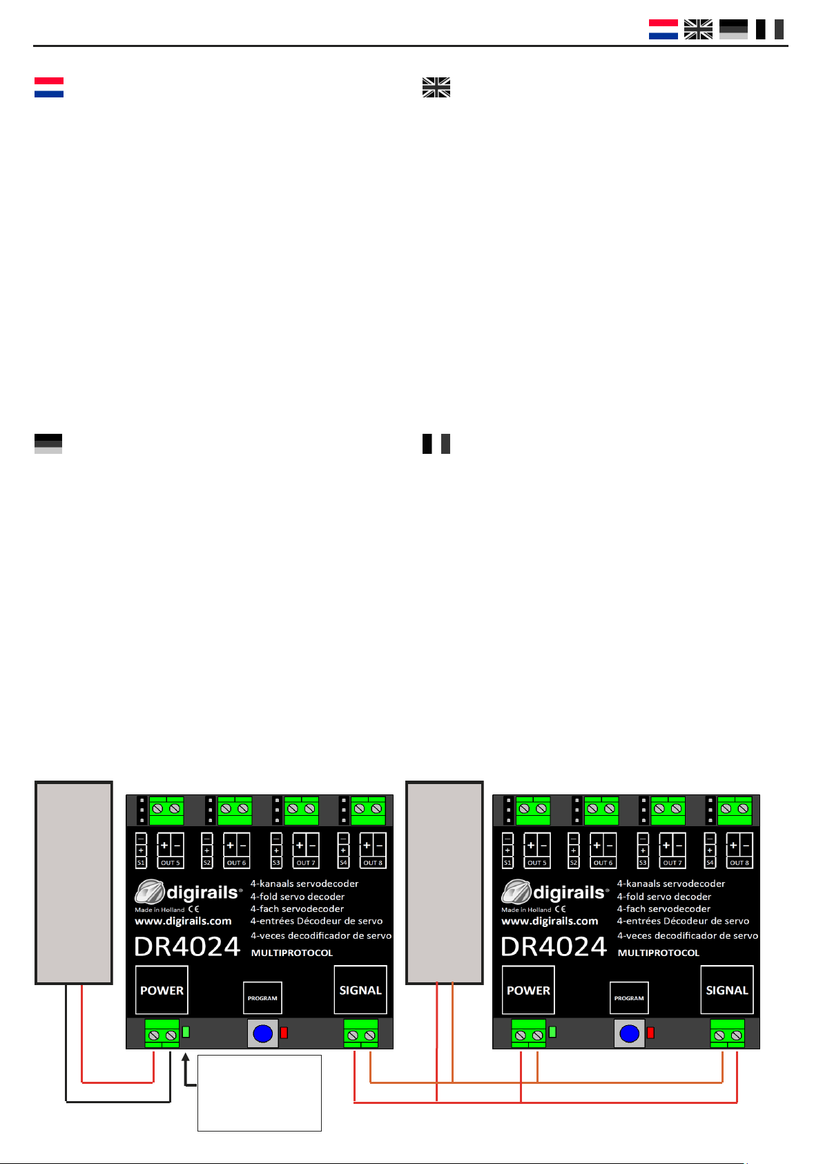
CENTRAL
UNIT
POWER SUPPLY
12—18 Volt
AC or DC
Short descripon
The DIGISERVO decoder is a fully programmable servo
decoder. Each output also has an extra switching out-
put to switch eg a light or decoupling track.
In addion, each output can be calibrated with so-
ware which makes installing the servos easier as they
can be set up aer they have been installed. The DI-
GISERVO decoder is the rst servo decoder that works
on the basis of funcon mapping. The decoder sees
the ‘switching addresses’ as control funcons for the
various outputs. The decoder can use 1 to 8 ‘switching
addresses’ depending on the mapping that has been
set up.
Kurzbeschreibung
Der DIGISERVO Decoder ist ein voll programmierbarer
Servo-Decoder. Jeder Ausgang verfügt auch über ei-
nen zusätzlichen Schaltausgang um z.B. ein Licht oder
ein Entkupplungsgleis zu schalten. Jeder Ausgang
kann auch mit Hilfe einer Soware kalibriert werden.
Das macht die Anbringung von Servos deutlich einfa-
cher, da sie nach der Montage eingestellt sind. Der
DIGISERVO Decoder ist der erste Servo-Decoder, der
auf Basis von Funkonsmapping arbeitet. Der Deco-
der erkennt die „Schaltadressen“ als Kontrollfunko-
nen der verschiedenen Ausgänge. Je nach erstelltem
Mapping, kann der Decoder ein bis acht
„Schaltadressen“ nutzen.
Courte descripon
Le décodeur DIGISERVO est un décodeur servo enè-
rement programmable. Chaque sore a également
une sore commutateur supplémentaire, tel qu’ une
lampe ou un rail découpleur. De plus, chaque sore
peut être calibrée par logiciel, ce qui facilite l’installa-
on des servos puisqu’ils peuvent être réglés après
avoir été installés. Le décodeur DIGISERVO est le pre-
mier décodeur servo qui fonconne sur base de map-
page de foncons (funcon mapping). Le décodeur
voit les “adresses de commutaon” comme des fonc-
ons de contrôle pour les diérentes sores. Le déco-
deur peut uliser de 1 à 8 “adresse de commutaon”
en foncon du mappage qui a été installé.
Spanningsindicator
Voltage indicator
Spannungsindikator
Témoin de tension

DR4024 DIGISERVO (v1.31)
Pagina / page / Seite / page 4
Uitgebreide beschrijving
Algemeen
De DIGISERVO decoder is een volledig programmeerbare, mulprotocol servodecoder. De decoder hee aan-
sluingen voor 4 modelbouw servo’s. Daarbij hee de decoder ook nog eens 4 aan-uit schakeluitgangen die ge-
lijkjdig op apart kunnen schakelen aankelijk van de gewenste congurae.
De DIGISERVO decoder is de eerste servodecoder die volledig werkt op basis van funce-mapping.
De decoder ziet de ‘wisseladressen’ als stuurfunces voor de diverse uitgangen. Aankelijk van de ingestelde
mapping kan de decoder 1 tot 8 ‘wissel’adressen in beslag nemen.
Elk herkend adres schakelt een virtuele schakelaar in de decoder.
Wisselcommando ‘recht’ (groen) schakelt de schakelaar in, Wisselcommand ‘auigend’ (rood) schakelt de scha-
kelaar uit.
Voor elke schakelaar zijn er twee funce-map CV groepen.
1 groep met 3 CVs voor de ‘Aan’ stand, 1 groep met 3 CVs voor de ‘Uit’ stand.
Via CV’s 141 –188 kan dan gekozen worden welke van de 4 Servo’s of uitgangen van de decoder geacveerd
moet worden.
Servo posies
De decoder hee 4 mogelijke posies (A, B, C, D) voor elke servo, welke door bovengenoemde mapping geac-
veerd kunnen worden. De resolue van deze posies bedraagt 0.4% van de volle uitslag. Bij een volledige draai
van 90 graden betekent dat 0.36 graad per stap. Standaard maakt de decoder gebruik van posie A en B.
Verder kan de decoder per servo zo worden ingesteld, dat bij het bereiken van de eindposie een gedempte
slingering rond de eindposie uitgevoerd wordt. ( massa simulae )
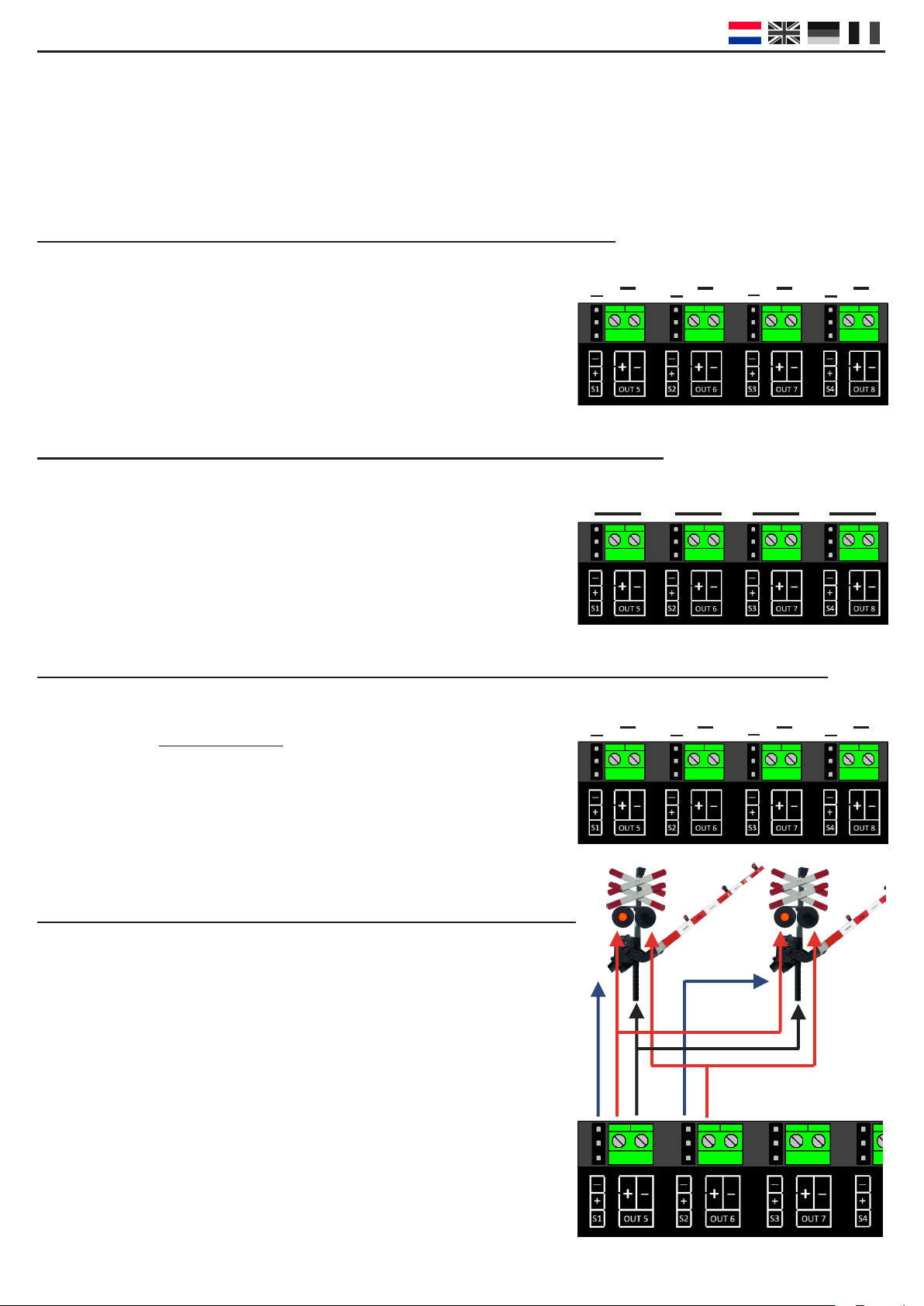
Schakeluitgangen
De servo- en schakeluitgangen zijn op de decoder gegroepeerd.
De schakeluitgangen hebben een FET schakelaar naar GND. De extra schakeluitgangen voeren de
gemeenschappelijke plus.
Het schakelmoment van deze uitgangen kan ook gekoppeld worden aan de bijbehorende servo.
Zo kan er op 1 van de eindposies of in de middenstand tussen de eindposies in geschakeld worden. Met deze
uitgangen kan bijvoorbeeld een relais voor puntstuk polarisae of stroomloos maken van een stopsece in ge-
val van seinaansturing.

DR4024 DIGISERVO (v1.31)
Pagina / page / Seite / page 5
Snelle simpele start
Doormiddel van onderstaande stappen kunt u direct aan de slag met de decoder als 4 Kanaals servodecoder
met 4 extra schakeluitgangen.
De module een adres geven
Om te beginnen hee de DR4024 decoder een adres nodig om te kunnen communiceren met uw centrale. Stan-
daard wordt de module geleverd op adres “1” en is de module ingesteld als servodecoder in DCC formaat.
Stap 1 :Sluit zowel de POWER + SIGNAL tegelijk aan op de rails of rails (track) uitgang van uw centrale.
Stap 2 :Stel uw centrale in op het begin adres dat u de module wilt geven.
Stap 3 :Druk de schakelaar op de decoderin totdat de rode led blij branden.
Stap 4 :Schakel nu op uw centrale het ingestelde adres.
Stap 5 :Als de module correct is aangesloten doo de led nadat u het gewenste adres hee gescha-
keld
Stap 6 : De eerste servo uitgang (OUT1) hee nu het door u gekozen adres gekregen. Alle volgende
servo uitgangen worden standaard voorzien van 1 nummer hoger.
Voorbeeld: U programmeert de module op adres 56 waarbij S1 adres 56 hee gekregen,
S2 nr 57, S3 nr 58, S4 nr 59, OUT1 nr 60, OUT2 nr. 61, OUT3 nr. 62 en OUT4 nr. 63.
Omdat de decoder mulprotocol is en DCC en Marklin Motorola ondersteund, zal het kiezen van een wissel-
adres ook het protocol selecteren. Tijdens het ontvangen van het wisselcommando zoals we in bovenstaande
volgorde hebben gedaan kijkt de decoder welk protocol gebruikt wordt en slaat dit op in zijn geheugen.
BELANGRIJK!
In DCC modus kunt u ieder willekeurig beginadres nummer kiezen waarbij de module automasch de opvolgen-
de uitgangen op 1 ophoogt. Het Motorola protocol werkt met groepen van 8 nummers. U kunt hierbij geen tus-
senadres kiezen als beginadres. VOORBEELD: adres 1 t/m 8 of 9 t/m 16 of 17 t/m 24 etc.
De module terug naar fabriekswaarden doormiddel van POM programmering
Doormiddel van onderstaande methode zet u de module terug naar fabriekswaarden via POM programmering.
Stap 1 : Sluit de signal ingang van de decoder aan op de rails uitgang van uw centrale.
Stap 2 : Zorg ervoor dat de module spanning krijgt via de power ingang van de module.
(U kunt ook de power en signal ingang met elkaar doorverbinden)
Stap 3 : Zet uw centrale in POM programmeer stand
(meer informae over POM staat in de handleiding van uw centrale)
Stap 5 : Kies locadres 9999 op uw centrale
Stap 6 : Druk eenmaal op de schakelaar van de module zodat de rode led gaat branden
Stap 7 : Programmeer vervolgens decimaal waarde 8 in CV8
Stap 8 : Druk eenmaal op de schakelaar van de module zodat de led doo
Stap 9 : Belangrijk bij een RESET is dat de module nu even zonder spanning komt te staan.
Dus koppel de decoder op zowel de power als de signal ingang los en wacht 3 tot 5 seconden.
Stap 10: De decoder kan terug onder spanning gezet worden en staat nu weer in de fabriekswaarden.
LET OP! De decoder hee vanaf nu ook weer adres 1

DR4024 DIGISERVO (v1.31)
Pagina / page / Seite / page 6
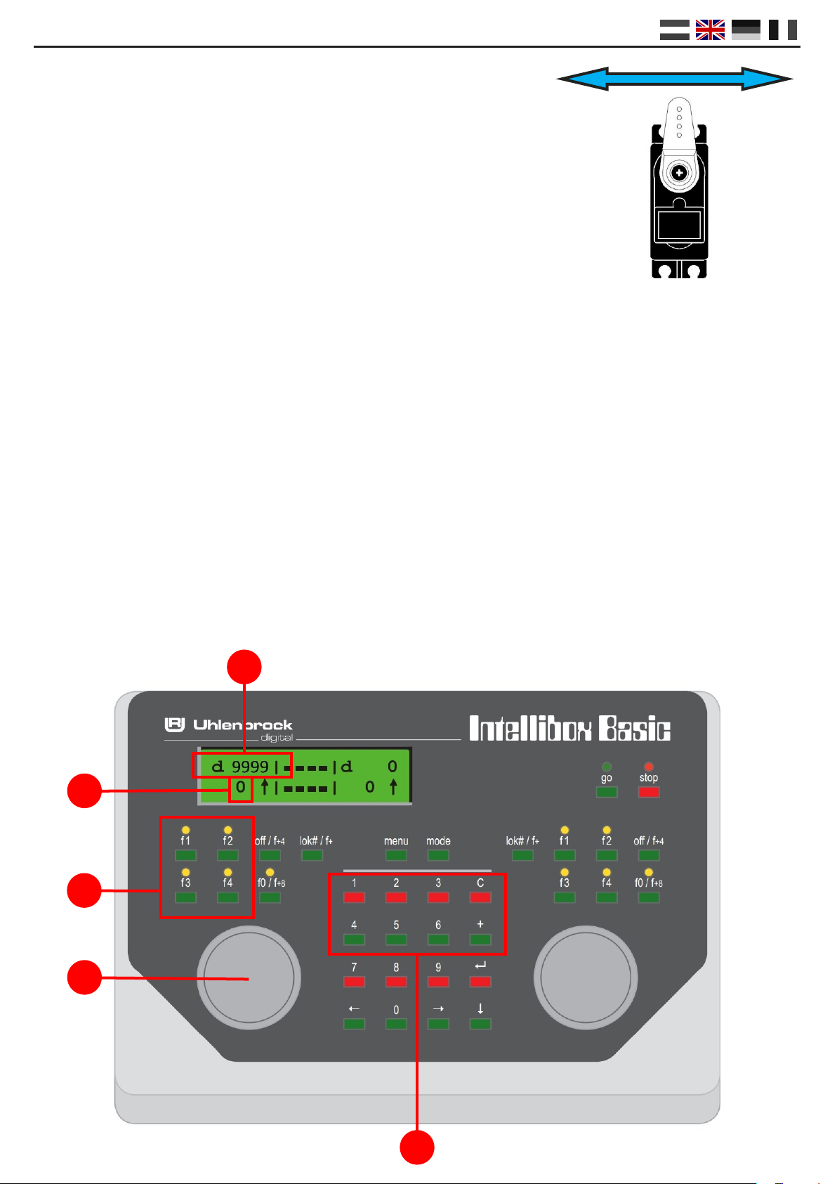
Servo posities instellen
Om de servo posities in te stellen, gebruikt u onderstaande procedure:
1. Sluit de decoder aan op de voeding en uw centrale.
2. Stel uw centrale in op locadres 9999 (128 stappen DCC)
3. Zet F1, F2, F3 en F4 op uw centrale allemaal uit
4. Zet de rijregelaar op 0
5. Bedien de servo die u gaat programmeren
6. Druk op de schakelaar van de module, de LED gaat branden.
De geselecteerde servo loopt naar de middenstand.
7. Draai de rijregelaar (7) vooruit (rechtsom) om de servo in de gewenste A posie in te stellen.
8. Schakel F1 aan en weer uit om posie A op te slaan in de module.
9. Keer de rijrichng op de centrale door de rijregelaar (7) éénmalig in te drukken.
10. Draai de rijregelaar (7) vooruit (rechtsom) om de servo in de gewenste B posie in te stellen.
11. Schakel F2 aan en weer uit om posie B op te slaan in de module.
12. Keer de rijrichng op de centrale door de rijregelaar (7) éénmalig in te drukken.
13. Draai de rijregelaar (7) vooruit (rechtsom) om de servo in de gewenste C posie in te stellen.
14. Schakel F3 aan en weer uit om posie C op te slaan in de module.
15. Keer de rijrichng op de centrale door de rijregelaar (7) éénmalig in te drukken.
16. Draai de rijregelaar (7) vooruit (rechtsom) om de servo in de gewenste D posie in te stellen.
17. Schakel F4 aan en weer uit om posie D op te slaan in de module.
Belangrijk: als de decoder een posie opslaat, knippert de LED zeer kort uit, ten teken van het
opslaan van de posie.
9. Druk op de schakelaar van de module om de programmeer modus af te sluiten.
10. Herhaal bovenstaande stappen voor iedere servo uitgang.
TIP: Door F0/Licht aan en weer uit te schakelen kiest u automatisch de volgende servo.
A
C
B
D
2
7
5
4
3

DR4024 DIGISERVO (v1.31)
Pagina / page / Seite / page 7
Instellingen (CV’s) wijzigen van de decoder
Het wijzigen van instellingen zoals schakeljd of het kiezen van één van de vele presets in CV47 kan op
2 verschillende manieren die hieronder worden beschreven.
CV Programmering / Uitlezing via programmeerspoor
Deze manier van programmeren is een veel gebruikte manier die vrij ingewikkeld kan zijn.
De DR4024 decoder is voorzien van een interne belasng weerstand. U hoe daarom ook geen
externe belasng aan te sluiten op de module.
Stap 1 : Sluit zowel power als signal ingang van de decoder aan op de rails uitgang van uw centrale.
Stap 2 : Druk de programmeer schakelaar op de decoder in totdat de rode led blij branden.
Stap 3 : Sluit nu zowel power als signal ingang van de decoder aan op de programmeer uitgang van uw
centrale
Stap 4 : Nu kunt u de gewenste CV’s wijzigen doormiddel van CV-byte of CV-bit programmering.
(Voor informae over CV-byte of CV-bit programmering raadpleegt u de handleiding van
uw centrale)
Stap 5 : Sluit zowel power als signal ingang van de decoder aan op de rails uitgang van uw centrale.
Stap 6 : Druk de programmeer schakelaar op de module in totdat de led doo.
Stap 7 : Uw wijzigingen zijn opgeslagen en de module is klaar voor gebruik.
CV Programmering via het hoofdspoor ( POM )
Een andere manier van programmeren is POM (Program On Main). Bij deze manier van programmeren kunt u
de module gewoon op de baan aansluiten zonder moeizame aansluingen of plaatsen van weerstanden zoals
bij programmeren via het aparte programmeerspoor.
Stap 1 : Sluit de signal ingang van de decoder aan op de rails uitgang van uw centrale.
Stap 2 : Zorg ervoor dat de module spanning krijgt via de power ingang van de decoder.
(U kunt ook de power en signal ingang met elkaar doorverbinden)
Stap 3 : Zet uw centrale in POM programmeer stand
(meer informae over POM staat in de handleiding van uw centrale)
Stap 5 : Kies locadres 9999 op uw centrale
Stap 6 : Druk op de schakelaar van de module totdat de led gaat branden
Stap 7 : Programmeer vervolgens de gewenste CV’s van de module
Stap 8 : Druk op de schakelaar van de module totdat de led doo
Stap 9 : De module is direct klaar voor gebruik met de door u gewijzigde instellingen.
LET OP!!! In sommige gevallen kan het nodig zijn dat u de DR4024 module opnieuw een adres moet geven
doormiddel van ‘de module een adres geven’ op pagina 5 van deze handleiding.

DR4024 DIGISERVO (v1.31)
Pagina / page / Seite / page 8
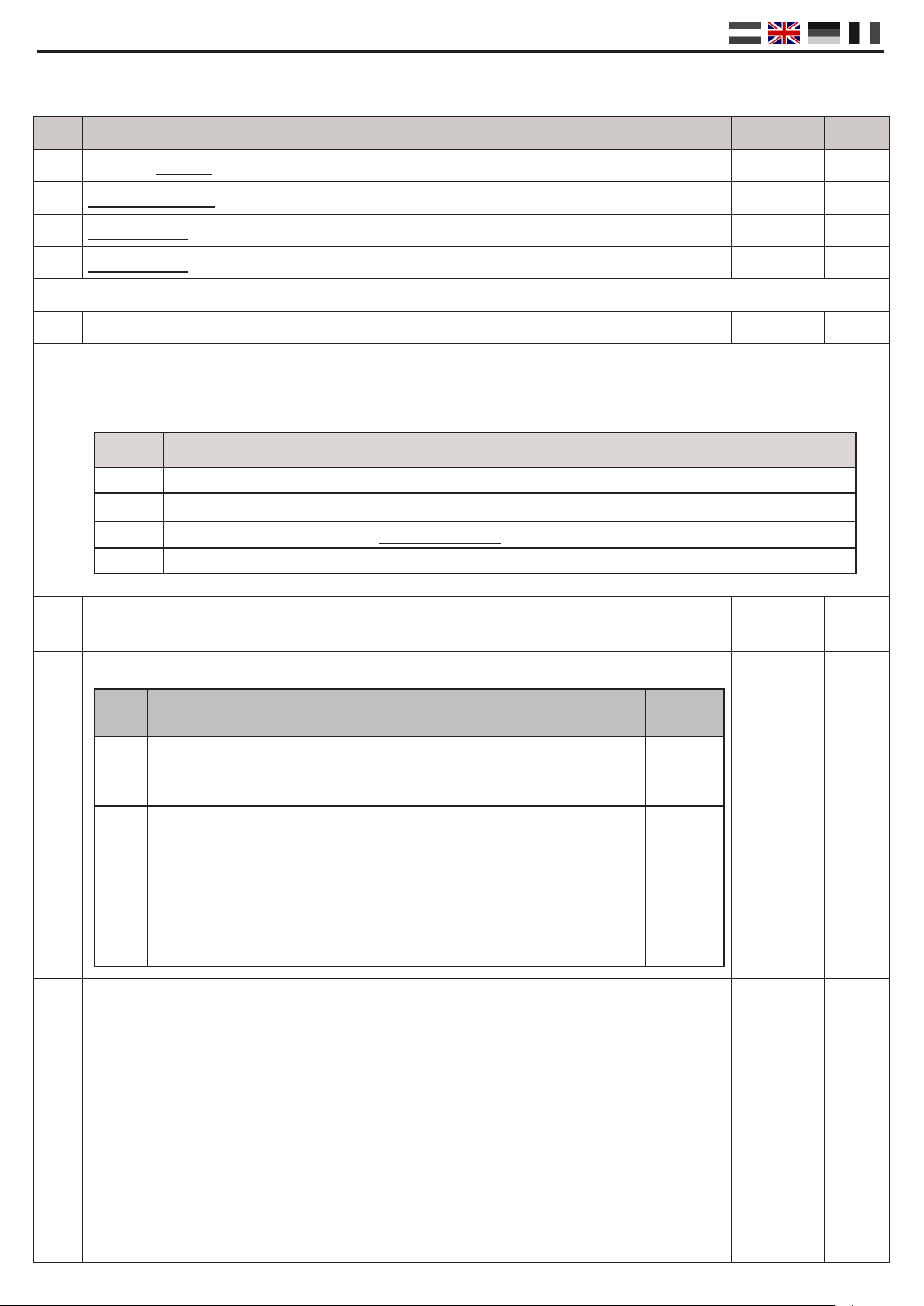
CV LIJST
CV CV Denie Bereik Waarde
7Versie van de decoder 10
8Fabrikant-id waarde “8” leidt ertoe dat de fabrieksinstellingen worden ingesteld. 42
17 Uitgebreid adres hoge byte 192-255 0
18 Uitgebreid adres lage byte 128-255 0
47 Voorinstellingen / Preset Alleen schrijaar 0 – 3 n/a
Om het programmeren iets eenvoudiger te maken is de DR4024 decoder uitgerust met een viertal Presets.
Door het acveren van een preset wordt de module volledig gecongureerd zonder dat u iedere CV handmag
hoe te wijzigen. Uitgebreide informave over de presets vind u op pagina 11
112 Knipperfrequene voor de schakeluitgangen met bit 7 acef in CV117 t/m CV120.
Waarde 20 is 90x per minuut.
0-255 20
113
-
116
CV’s 113-116 hebben alle dezelfde betekenis voor de verschillende servos van 1 - 4.
0-255 2
117 CV’s 117-120 hebben alle dezelfde betekenis voor de verschillende schakeluitgangen van 1
- 4. Schakeluitgang 1 (OUT 5)
Bits 0-1 stellen het schakelmoment voor de ‘Aan’ stand van de bijbehorende logische
schakelaar in. Bits 4-5 stellen het schakelmoment voor de ‘Uit’ stand van de bijbehorende
logische schakelaar in.
Bit 0 = servo onaankelijk schakelen
Bit 1 = schakelen als bijbehorende servo Posie A hee bereikt
Bit 2 = schakelen als bijbehorende servo Posie B hee bereikt
Bit 3 = schakelen als bijbehorende servo tijdens het bewegen het midden tussen Positie A en
Posie B passeert
Bit 7 Uitgang knippert met frequene gezet in CV 112
0-255
1
Waarde Funce
0Preset 0 ----> 4 Servo’s (1 t/m 4) en 4 aparte schakeluitgangen (5 t/m 8)
1Preset 1 ----> 4 Servo’s (1 t/m 4) met gekoppelde schakeluitgangen (1 t/m 4)
2Preset 2 ----> 4 Servo’s met massa simulae (1 t/m 4) en 4 aparte schakeluitgangen (5 t/m 8)
3Preset 3 ----> Overweg met AHOB, 2 slagbomen en massa simulae
Bit Funce Waarde
0-3Stelt de servo-stapgrooe in.
Waarde 15 is snelst aan,
waarde 0 is langzaamst.
2
0-15
4-7Stelt de servo-stapsnelheid in.
Waarde 15 kleinste en waarde 0 de grootste. 0 komt overeen met 50
stappen per seconde. 1 met 25/s, 2 met 12/s, 3 met 5/s, 4 met 4/s.
etc.. Tot 15 met 1 stap / seconde.
Bij de laatste instelling in combinae met bit 0-3 op 0, stapt de servo
tussen de twee uiterste standen in 126 seconden !
0
(0-15)
*16

DR4024 DIGISERVO (v1.31)
Pagina / page / Seite / page 9
CV CV Denie Bereik Waarde
118 Schakeluitgang 2 (OUT 6)
Voor instellingen zie CV117
0-255 1
119 Schakeluitgang 3 (OUT 7)
Voor instellingen zie CV 117
0-255 1
120 Schakeluitgang 4 (OUT 8)
Voor instellingen zie CV 117
0-255 1
121 Posie A voor servo 1
CV’s 121-136 bevaen de diverse eindposies van de servo’s. Elke servo kent 4 eind-
posies: A,B,C,D Deze eindposies kunnen gekozen worden middels de funce map-
ping (zie pagina 10)
0-255 224
122 Posie C voor servo 1 0-255 176
123 Posie B voor servo 1 0-255 32
124 Posie D voor servo 1 0-255 80
125 Posie A voor servo 2 0-255 224
126 Posie C voor servo 2 0-255 176
127 Posie B voor servo 2 0-255 32
128 Posie D voor servo 2 0-255 80
129 Posie A voor servo 3 0-255 224
130 Posie C voor servo 3 0-255 176
131 Posie B voor servo 3 0-255 32
132 Posie D voor servo 3 0-255 80
133 Posie A voor servo 4 0-255 224
134 Posie C voor servo 4 0-255 176
135 Posie B voor servo 4 0-255 32
136 Posie D voor servo 4 0-255 80
137 CV’s 137-140 bevaen de Massa simulae waarde.
Als deze waarde ongelijk 0 is, zal de servo de deze waarde afwisselend bij de eindposi-
e optellen en arekken, waarbij gelijkjdig bij optellen of arekken de waarde met 1
verminderd wordt, totdat deze ook 0 is geworden.
Het eect is, dat de servo rond zijn eindposie gedempt heen en weer gaat slingeren.
Voorwaarde voor de goede werking is, dat eindposie + bouncewaarde kleiner dan
255 is en dat eindposie – bouncewaarde groter dan 0 is.
0-63 0
138 Massa simulae waarde voor servo 2 (zie CV137) 0-63 0
139 Massa simulae waarde voor servo 3 (zie CV137) 0-63 0
140 Massa simulae waarde voor servo 4 (zie CV137) 0-63 0
DR4024 DIGISERVO (v1.31)
Pagina / page / Seite / page 10
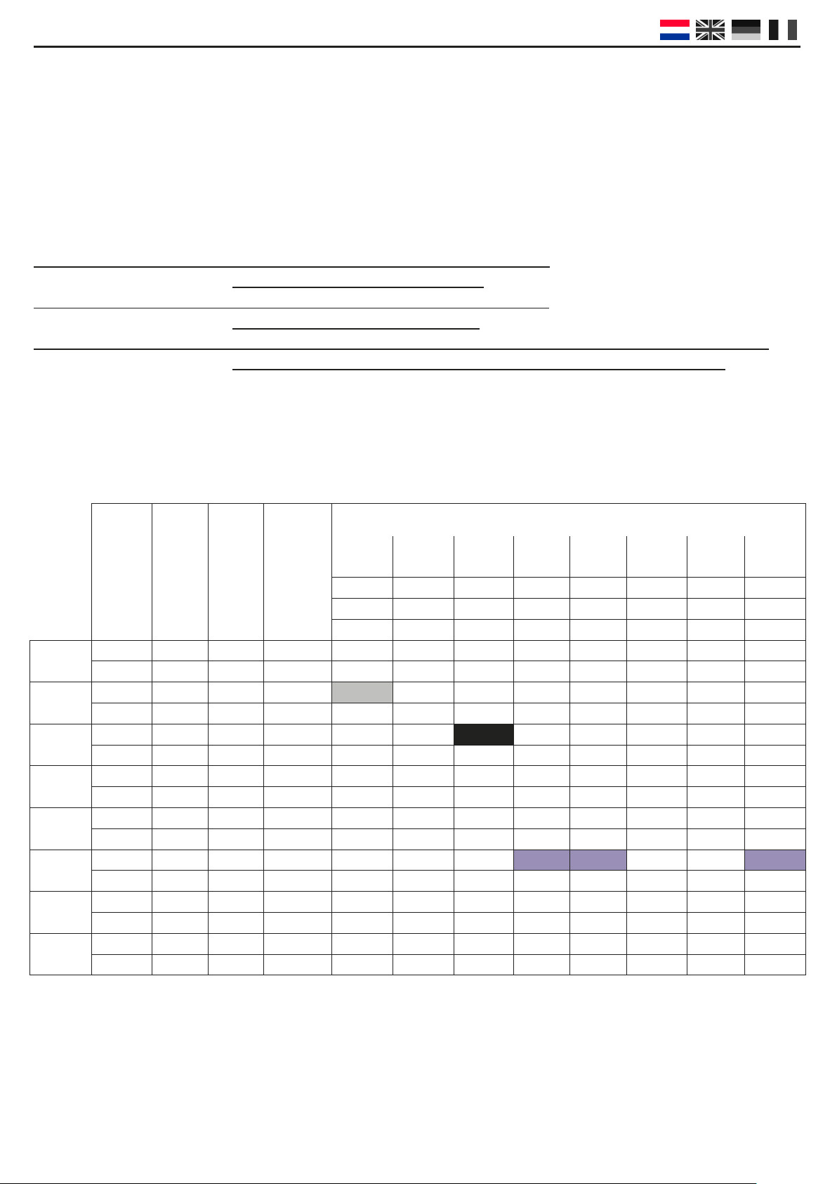
Funcemappen
Via onderstaande tabel kunt u de verschillende uitgangen van de DR4024 module (1 t/m 8) koppelen aan de
schakeltoetsen op uw centrale. Dit kan handig zijn op het moment dat u met 1 toets meerdere uitgangen tege-
lijk zou willen schakelen. In het geval dat u meerdere uitgangen wilt schakelen op 1 funcetoets in dezelfde
groep telt u de waarden bij elkaar op.
Voorbeeld 1 (grijs): Toets 2 moet servo 1, posie A AAN schakelen
U programmeert in CV147 waarde 1
Voorbeeld 2 (zwart): Toets 3 moet servo 2, posie C AAN schakelen
U programmeert in CV154 waarde 4
Gecombineerd voorbeeld: Toets 6 moet servo 3 posie A + servo 4 posie B en OUTPUT 8 AAN schakelen
U programmeert in CV171 waarde 16 + 128 = 144 en in CV173 waarde 8
Stand CV
(A+B)
CV
(C+D) OUTPUT
SERVO POSITIES A, B, C, D
S1
(A)
S1
(B)
S2
(A)
S2
(B)
S3
(A)
S3
(B)
S4
(A)
S4
(B)
ABABABAB
CDCDCDCD
OUT 5 OUT 6 OUT 7 OUT 8
Toets 1 AAN 141 142 143 124816 32 64 128
UIT 144 145 146 124816 32 64 128
Toets 2 AAN 147 148 149 124816 32 64 128
UIT 150 151 152 124816 32 64 128
Toets 3 AAN 153 154 155 124816 32 64 128
UIT 156 157 158 124816 32 64 128
Toets 4 AAN 159 160 161 124816 32 64 128
UIT 162 163 164 124816 23 64 128
Toets 5 AAN 165 166 167 124816 32 64 128
UIT 168 169 170 124816 32 64 128
Toets 6 AAN 171 172 173 124816 32 64 128
UIT 174 175 176 124816 32 64 128
Toets 7 AAN 177 178 179 124816 32 64 128
UIT 180 181 182 124816 32 64 128
Toets 8 AAN 183 184 185 124816 32 64 128
UIT 186 187 188 124816 32 64 128
* De GROEN gekleurde getallen zijn de standaard fabriekswaarden voor SERVO 1 t/m 4
* De ROOD gekleurde getallen zijn de standaard fabriekswaarden voor OUTPUT 5 t/m 8
DR4024 DIGISERVO (v1.31)
Pagina / page / Seite / page 11
PRESET 0 (STANDAARD)
4 Servo’s (1 t/m 4) en 4 aparte schakeluitgangen (5 t/m 8)
Met preset 0 krijgt de module automasch 8 adressen.
1 t/m 4 worden gereserveerd voor de 4 servo uitgangen.
5 t/m 8 worden gereserveerd voor de 4 extra schakeluitgangen
OUT5 t/m OUT8.
PRESET 1
4 Servo’s (1 t/m 4) met gekoppelde schakeluitgangen (1 t/m 4)
Met preset 1 krijgt de module automasch 4 adressen (1 t/m 4).
De extra schakeluitgangen worden gekoppeld aan de servo uitgangen
waarbij de extra schakeluitgangen zullen schakelen bij de
middenstand van de servo. Deze preset is te gebruiken als u op de
schakeluitgang een relais voor puntstukpolarisae aansluit.
PRESET 2
4 Servo’s met massa simulae (1 t/m 4) en 4 aparte schakeluitgangen (5 t/m 8)
Met preset 2 krijgt de module automasch 8 adressen. 1 t/m 4
worden gereserveerd voor de 4 servo uitgangen S1 t/m S4 waarbij
automasch de massa simulae geacveerd wordt op iedere servo
uitgang. 5 t/m 8 worden gereserveerd voor de 4 extra
schakeluitgangen OUT 5 t/m OUT8.
PRESET 3
Overweg met AHOB, 2 slagbomen en massa simulae
Met preset 3 krijgt de module automasch 2 adressen.
_1_ _2_ _3_ _4_
6785
1234
6785
1234
PRESETS
Om het programmeren wat eenvoudiger te maken, staan er vier z.g. preset-CV’s ter beschikking.
U programmeert de presets in CV47. Deze alleen schrijare CV stelt automasch een aantal standaard eecten
in. U kunt deze CV dus niet op een later jdsp uitlezen.
Uiteraard kunt u na het kiezen van de presets als basis, zelf uw fanta-
sie de vrije loop laten door andere eecten in te
schakelen. Zo zou u bijvoorbeeld preset 2 als basis kunnen gebruiken
voor een sein met treinbeinvloeding: Funcemapping dusdanig aan-
passen dat de uitgangen ook aanschakelen samen met de servo’s. En
de outputcongurae zo instellen, dat geschakeld wordt bij het be-
reiken van de groene stand.

DR4024 DIGISERVO (v1.31)
Pagina / page / Seite / page 12
Detailed descripon
General
The DIGISERVO decoder is a fully programmable, mul-protocol servo decoder. The decoder has connecons
for 4 model-making servos. In addion, the module has a further 4 on-o switching outputs which can switch
simultaneously or separately, according to the desired conguraon.
The DIGISERVO decoder is the rst servo decoder that operates enrely on the basis of funcon mapping. The
decoder sees the ‘switching addresses’ as control funcons for the various outputs. The decoder can use 1 to 8
‘switching addresses’ depending on the mapping that has been set up.
Each address that is recognised controls a virtual switch in the decoder.
The switching command ‘right’ (green) turns the switch on; the switching command ‘turn o’ (red) turns the
switch o.
There are two funcon map CV groups for each switch.
1 group with 3 CVs for ‘on’, 1 group with 3 CVs for ‘o’.
CVs 141-188 can then be used to select which of the 4 servos or decoder outputs should be acvated.
Servo posions
The decoder has 4 possible posions (A, B, C, D) for each servo, which can be acvated with the mapping men-
oned above. The resoluon of these posions is 0.4% of full range of movement. For a complete turn of 90 de-
grees, this means 0.36 degrees per step. The decoder uses posions A and B by default.
The decoder can also be set up per servo to carry out a damped oscillaon when the end posion is reached
(mass simulaon).
Switching outputs
The servo and switching outputs are grouped in the decoder.
The switching outputs have an FET switch to GND. The extra switching outputs feed the common plus.
The moment these outputs switch can also be linked to the corresponding servo.
For example, the switch can be acvated at one out of the end posions or in the middle posion between the
end posions. These outputs can be used, for example, to polarise or de-energise a points relay (US: railroad
switch relay) for a stop secon in the event of signal control.

DR4024 DIGISERVO (v1.31)
Pagina / page / Seite / page 13
Quick start
By following these steps you can immediately start using the decoder as a 4-channel servo decoder with 4 extra
switching outputs.
Giving the module an address
The DR4024 module requires an address in order to be able to communicate with your control unit.
By default, the module is delivered with the address ‘1’ and is set up as a servo decoder in DCC format.
Step 1: Connect both the POWER + SIGNAL to the rails or rails (track) output on your control unit at
the same me.
Step 2: Set your control unit to the starng address that you want to give the module.
Step 3: Press and hold the programming switch on the module unl the red LED remains lit.
Step 4: Now switch to the address you entered on your control unit.
Step 5: If the module is connected correctly, the LED will turn o aer you switch to the desired
address
Step 6: The rst servo output (OUT1) has now been given the address you chose. All subsequent servo
outputs are given address one number higher.
Example: You programmed the module to address 56, meaning S1 has been given address 56,
S2 no. 57, S3 no. 58, S4 no. 59, OUT1 no. 60, OUT2 no. 61, OUT3 no. 62 and OUT4 no. 63.
Because the decoder is mul-protocol and supports DCC and Marklin Motorola, choosing an address also se-
lects the protocol. When receiving a switching command, as in the above steps, the decoder idenes which
protocol is used, and stores this in its memory.
IMPORTANT!
In DCC mode, you can choose any start address you like and the module will automacally assign successive
outputs a higher address in increments of 1. The Motorola protocol works with groups of 8 numbers. You can-
not choose a mid-range address as the start address. EXAMPLE: Address 1-8 or 9-16 or 17-24 etc.
Returning the module to factory sengs using POM programming
Follow the steps below to set the module back to factory sengs using POM programming.
Step 1 : Connect the signal input on the decoder to the rails output of your control unit.
Step 2 : Ensure the module is supplied with voltage via the power input on the module.
(You can also connect the power and signal inputs to each other)
Step 3 : Set your control unit to POM programming mode
(more informaon about POM can be found in your control unit’s manual)
Step 5 : Choose loc address 9999 on your control unit
Step 6 : Press the switch on the module once so that the red LED comes on
Step 7 : Program decimal value 8 at CV8
Step 8 : Press the switch on the module once so that the LED goes out
Step 9 : It is important during a RESET that the module is not supplied with a voltage for a short me.
To do this, disconnect both the power and signal inputs on the decoder and wait 3 to 5 seconds.
Step 10: The power can now be reconnected and the module will be back to its factory sengs.
CAREFUL! The decoder now has address 1 again.
DR4024 DIGISERVO (v1.31)
Pagina / page / Seite / page 14
Setting up the servo positions
Follow this procedure to set up the servos:
1. Connect the decoder to the power and the control unit.
2. Set your control unit to loc address 9999 (128 steps DCC)
3. Turn o F1, F2, F3 and F4 on your control unit
4. Set the speed to 0
5. Operate the servo you want to program
6. Press the switch on the module. The LED will turn on.
The selected servo moves to the centre posion.
7. Turn the dial (7) clockwise to set the servo to the desired posion A.
8. Switch F1 on and then o to save posion A in the module.
9. Switch the travel direcon on the control unit by pressing dial (7) in once.
10. Turn the dial (7) clockwise to set the servo to the desired posion B.
11. Switch F2 on and then o to save posion B in the module.
12. Switch the travel direcon on the control unit by pressing dial (7) in once.
13. Turn the dial (7) clockwise to set the servo to the desired posion C.
14. Switch F3 on and then o to save posion C in the module.
15. Switch the travel direcon on the control unit by pressing dial (7) in once.
16. Turn the dial (7) clockwise to set the servo to the desired posion D.
17. Switch F4 on and then o to save posion D in the module.
Important: when the decoder saves a posion, the LED will turn o briey to show the posion has been
stored.
18. Press the buon on the module to exit the programming mode.
19. Repeat the above steps for each servo output.
TIP: You automatically select the next servo with F0 / turning the light on and off again.
2
7
5
4
3
A
C
B
D

DR4024 DIGISERVO (v1.31)
Pagina / page / Seite / page 15
Changing sengs (CVs) on the decoder
Changing sengs such as switching mes or choosing one of the many presets in CV47 can be done n 2 die-
rent ways as described below.
CV programming / reading via the programming track
This method of programming is commonly used but can be complicated.
The DR4024 servo module is equipped with an internal load resistor. This means you do not need to aach an
external resistor to the module.
Step 1 : Connect both power and signal inputs on the decoder to the rails output on your control unit.
Step 2 : Press and hold the programming switch on the module unl the red LED stays on.
Step 3 : Now connect both the power and signal inputs on the decoder to the programming output on your
control unit.
Step 4 : Now you can change the desired CVs with CV-byte or CV-bit programming.
(Refer to your control unit’s manual for informaon about CV-byte or CV-bit programming)
Step 5 : Connect both power and signal inputs on the decoder to the rails output on your console.
Step 6 : Press the programming switch on the module unl the LED goes out.
Step 7 : Your changes are saved and the module is ready for use.
CV programming via the main track ( POM )
Another method of programming is POM (Program On Main). With this type of programming, you can simply
connect the module to the track without the laborious job of making connecons or adding resistors as requi-
red when programming via the separate programming track.
Step 1 : Connect the signal input on the decoder to the rails output on your control unit.
Step 2 : Ensure the module is supplied with voltage via the power input on the module.
(You can also connect the power and signal inputs to each other)
Step 3 : Adjust your control unit to POM programming mode
(more informaon about POM can be found in the control unit’s manual)
Step 5 : Select loc address 9999 on your control unit
Step 6 : Press the switch on the module unl the red LED comes on
Step 7 : Program the required CVs on the module
Step 8 : Press the buon on the module unl the LED turns o
Step 9 : The module is ready for use with the new sengs.
CAUTION! In some cases it may be necessary to give the DR4024 module an address again by following the in-
strucons outlined in ‘Giving the module an address’ on page 13 of this manual.
DR4024 DIGISERVO (v1.31)
Pagina / page / Seite / page 16
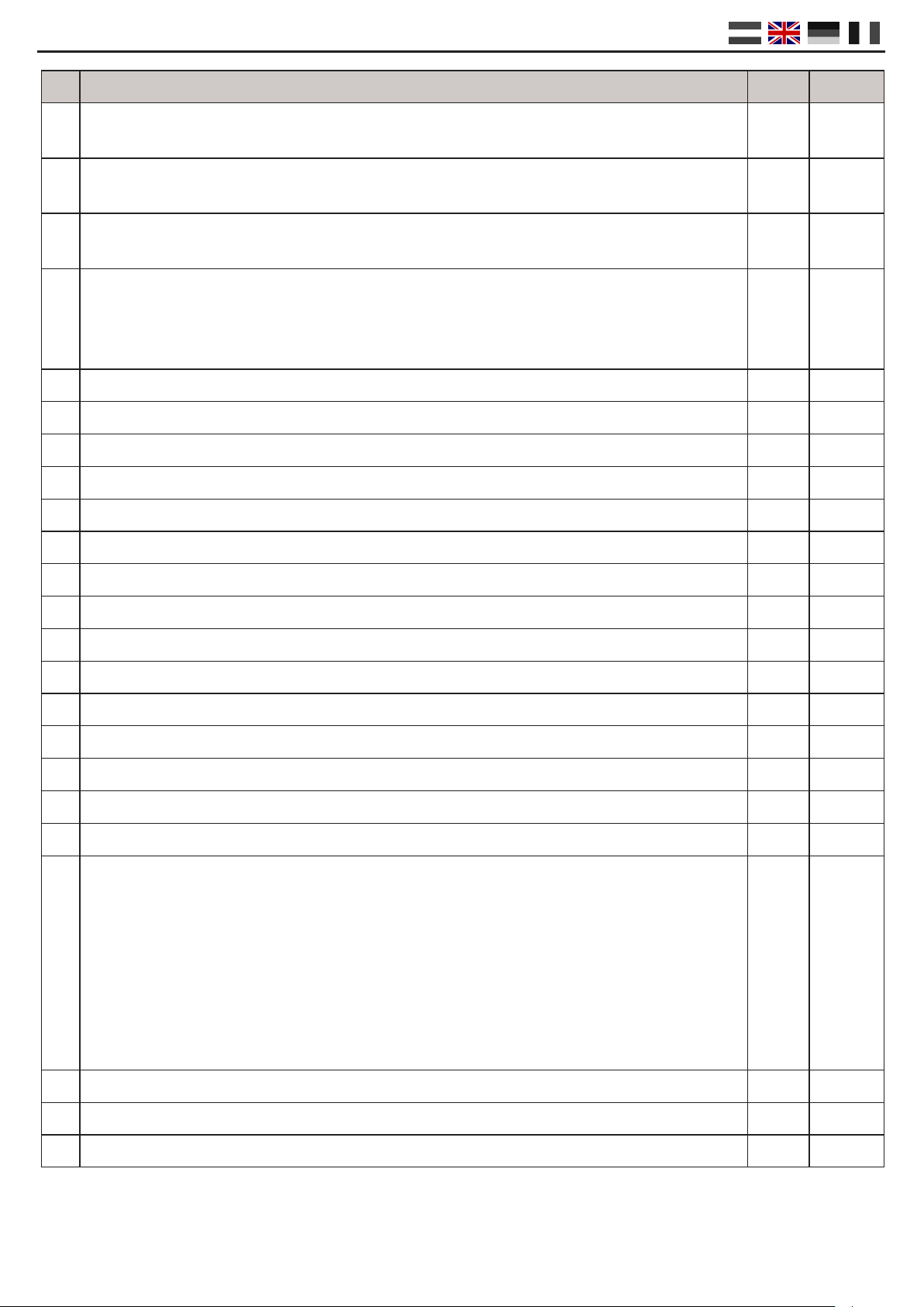
CV LIST
CV CV Denion Range Value
7Decoder version 10
8Manufacturer ID value ‘8’ returns the unit to factory sengs. 42
17 Long address high byte 192-255 0
18 Long address low byte 128-255 0
47 Presets Write-only 0 – 3 n/a
The DR4024 module has four presets to make programming easier. Each preset fully congures the module
without you having to change each CV manually. Detailed informaon about the presets can be found on
page 19.
112 Flashing frequency for the switching outputs with bit 7 acve in CV117 - CV120. Va-
lue 20 is 90x per minute.
0-255 20
113
-
116
CVs 113-116 have the same funcon for servos 1-4 respecvely.
.
0-255 2
117 CVs 117-120 have the same funcon for switching outputs 1-4 respecvely.
Switching output 1 (OUT 5)
Bits 0-1 set the switching me for the ‘on’ posion of the associated logical
switch. Bits 4-5 set the switching me for the ‘o’ posion of the corresponding
logical switch.
Bit 0 = switch servo independently
Bit 1 = switch when corresponding servo reaches posion A
Bit 2 = switch when corresponding servo reaches posion B
Bit 3 = switch when corresponding servo reaches the midway point between posions A
and B
Bit 7 output ickers with the frequency set in CV 112
0-255
1
Value Function
0Preset 0 ----> 4 servos (1-4) and 4 separate switching outputs (5-8)
1Preset 1 ----> 4 servos (1-4) with connected switching outputs (1-4)
2Preset 2 ----> 4 servos with mass simulation (1-4) and 4 separate switching outputs (5-8)
3Preset 3 ----> Crossing with AHOB, 2 barriers and mass simulation
Bit Function Value
0-3Sets the servo step size.
Value 15 is the fastest;
Value 0 is the slowest.
2
0-15
4-7Sets the servo step speed.
Value 15 is the smallest and value 0 is the largest. 0 corresponds to
50 steps per second. 1 = 25/s, 2 = 12/s, 3 = 5/s, 4 = 4/s. Etc... Max
value 15 = 1 step / second.
The last seng in combinaon with bits 0-3 set to 0 causes the ser-
vo to switch between the two extreme posions in 126 seconds!
0
(0-15)
*16
DR4024 DIGISERVO (v1.31)
Pagina / page / Seite / page 17
CV CV Denion Range Value
118 Switching output 2 (OUT 6)
For sengs see CV117
0-255 1
119 Switching output 3 (OUT 7)
For sengs see CV 117
0-255 1
120 Switching output 4 (OUT 8)
For sengs see CV 117
0-255 1
121 Posion A for servo 1
CVs 121-136 contain the various end posions of the servos. Each servo has 4 nal po-
sions: A, B, C, D. These end posions can be selected using funcon mapping
(see page 18)
0-255 224
122 Posion C for servo 1 0-255 176
123 Posion B for servo 1 0-255 32
124 Posion D for servo 1 0-255 80
125 Posion A for servo 2 0-255 224
126 Posion C for servo 2 0-255 176
127 Posion B for servo 2 0-255 32
128 Posion D for servo 2 0-255 80
129 Posion A for servo 3 0-255 224
130 Posion C for servo 3 0-255 176
131 Posion B for servo 3 0-255 32
132 Posion D for servo 3 0-255 80
133 Posion A for servo 4 0-255 224
134 Posion C for servo 4 0-255 176
135 Posion B for servo 4 0-255 32
136 Posion D for servo 4 0-255 80
137 CVs 137-140 contain the mass simulaon values.
If the value is not equal to 0, the servo will alternately add and subtract this value at
the end posion, whereby the value is also decreased by 1 each me, unl the value
reaches 0.
This causes the servo to oscillate back and forth less and less around its end posion. A
precondion for this working is that the end posion + the bounce value is less than
255 and that the end posion - the bounce value is greater than 0.
0-63 0
138 Mass simulaon value for servo 2 (see CV137) 0-63 0
139 Mass simulaon value for servo 3 (see CV137) 0-63 0
140 Mass simulaon value for servo 4 (see CV137) 0-63 0

DR4024 DIGISERVO (v1.31)
Pagina / page / Seite / page 18
Funcon mapping
The table below shows how to link the various outputs on the DR4024 module (1-8) to the switching buons on
your control unit. This can be useful when you want to switch mulple outputs simultaneously with one buon.
If you want to switch mulple outputs in the same group with one funcon buon, you add the values
together.
Example 1 (grey): Buon 2 switches servo 1 posion A ON
Program value 1 at CV147
Example 2 (black): Buon 3 switches servo 2 posion C ON
Program value 4 at CV154
Combined example: Buon 6 switches servo 3 posion A + servo 4 posion B + OUTPUT 8 ON
Program values 16 + 128 = 144 at CV171 and value 8 at CV173
Status CV
(A+B)
CV
(C+D) OUTPUT
SERVO POSITIONS A, B, C, D
S1
(A)
S1
(B)
S2
(A)
S2
(B)
S3
(A)
S3
(B)
S4
(A)
S4
(B)
ABABABAB
CDCDCDCD
OUT 5 OUT 6 OUT 7 OUT 8
Buon
1
ON 141 142 143 124816 32 64 128
OFF 144 145 146 124816 32 64 128
Buon
2
ON 147 148 149 124816 32 64 128
OFF 150 151 152 124816 32 64 128
Buon
3
ON 153 154 155 124816 32 64 128
OFF 156 157 158 124816 32 64 128
Buon
4
ON 159 160 161 124816 32 64 128
OFF 162 163 164 124816 23 64 128
Buon
5
ON 165 166 167 124816 32 64 128
OFF 168 169 170 124816 32 64 128
Buon
6
ON 171 172 173 124816 32 64 128
OFF 174 175 176 124816 32 64 128
Buon
7
ON 177 178 179 124816 32 64 128
OFF 180 181 182 124816 32 64 128
Buon
8
ON 183 184 185 124816 32 64 128
OFF 186 187 188 124816 32 64 128
* The GREEN numbers are the standard factory sengs for SERVO 1-4
* The RED numbers are the standard factory sengs for OUTPUT 5-8

DR4024 DIGISERVO (v1.31)
Pagina / page / Seite / page 19
PRESET 0 (STANDARD)
4 servos (1-4) and 4 separate switching outputs (5-8)
Preset 0 automacally gives the module 8 outputs.
1-4 are reserved for the 4 servo outputs.
5-8 are reserved for the 4 extra switching outputs OUT5 - OUT8.
PRESET 1
4 servos (1-4) with connected switching outputs (1-4)
Preset 1 automacally gives the module 4 addresses (1-4).
The extra switching outputs are coupled with the servo outputs,
whereby the extra switching outputs will switch when the servo rea-
ches the midway posion. This preset is for when you aach a relay
for point (US: railroad switch) polarisaon to the switching output.
PRESET 2
4 servos with mass simulaon (1-4) and 4 separate switching outputs (5-8)
Preset 2 automacally gives the module 8 outputs. 1-4 are reserved for the 4
servo outputs S1-S4, whereby the mass simulaon is automacally ac-
vated on each servo output. 5-8 are reserved for the 4 extra swit-
ching outputs OUT5 - OUT8.
_1_ _2_ _3_ _4_
6785
1234
6785
1234
PRESETS
There are four preset CVs to make programming a lile easier.
The presets are programmed in CV47. This write-only CV automacally sets a number of standard eects. You
cannot read this CV at a later me.
Let your imaginaon run wild by using the presets as a starng point
for seng up other eects. For example, you might use preset 2 as a
basis for a signal which inuences a train’s behaviour: Adjust the
funcon mapping so that the outputs switch along with the servos
and set up the output conguraon so that it switches when the
green mode is reached.
Important: The servo speed and end posions are not adjusted
by the presets!
PRESET 3
Crossing with AHOB, 2 barriers and mass simulaon

DR4024 DIGISERVO (v1.31)
Pagina / page / Seite / page 20
Ausführliche Beschreibung
Allgemein
Der DIGISERVO Decoder ist ein voll programmierbarer, Mulprotokoll Servo-Decoder. Der Decoder verfügt über
Anschlüsse für 4 Modellbau Servos. Zudem verfügt das Modul über 4 zusätzliche Ein/Aus Schalteingänge, die
entweder simultan oder individuell schalten können, je nach Konguraon.
Der DIGISERVO Decoder ist der erste Servo-Decoder der ausschließlich auf Basis von Funkonsmapping funko-
niert. Der Decoder erkennt die “Schaltadressen” als Kontrollfunkonen der verschiedenen Ausgänge. Der Deco-
der kann zwischen 1 und 8 “Schaltadressen” nutzen, je nach dem erstellten Mapping.
Jede erkannte Adresse kontrolliert in dem Decoder einen virtuelle Schalter.
Das Schaltkommando “rechts” (grün) stellt den Schalter ein, während das Schaltkommando “ausschalten” (rot)
den Schalter ausstellt.
Es gibt für jeden Schalter zwei Funkonsmapping CV Gruppen.
1 Gruppe mit 3 CVs für ‘ein’, 1 Gruppe mit 3 CVs für ‘aus’.
CVs 141-188 können dann genutzt werden, um auszuwählen welcher der vier Servos- oder Decoder-Ausgänge
akviert werden soll.
Servo-Posionen
Der Decoder hat 4 mögliche Posionen (A, B, C, D) für jeden Servo, die mit dem oben erwähnten Mapping ak-
viert werden können. Die Resoluon dieser Posionen beträgt 0.4% des gesamten Bewegungsumfangs. Für eine
volle 90 Grad Wendung bedeutet dies 0.36 Grad pro Schri. Der Decoder benutzt standardmäßig Posionen A
und B.
Der Decoder kann auch pro Servo so eingestellt werden, dass eine gedämpe Schwankung beim Erreichen der
Endposion durchgeführt wird (Massensimulaon).
Schaltausgänge
Die Servo– und Schaltausgänge sind in dem Decoder gruppiert.
Die Schaltausgänge haben einen FET der nach GND geschaltet werden kann. Die zusätzlichen Schaltausgänge
versorgen den gemeinsamen Pluspol.
Der Schaltmoment dieser Ausgänge kann auch mit dem entsprechenden Servo verknüp werden.
Zum Beispiel kann der Schalter an einer der Endposionen akviert werden, oder mien zwischen den Endposi-
onen. Diese Ausgänge können zum Beispiel benutzt werden, um ein Relais für Weichenstellungen zu polarisie-
ren oder stromlos zu machen für einen Stoppabschni bei Signalanschluss.
Table of contents
Languages:
Other digirails Media Converter manuals

Popular Media Converter manuals by other brands


Orban
Orban OPTICODEC-PC 1010 Technical manual

gefran
gefran SIEIDrive EXP-F2E instruction manual

MA lighting
MA lighting MA VPU user manual

Pepperl+Fuchs
Pepperl+Fuchs PVS58X Series operating instructions

Thinklogical
Thinklogical SDI to HDMI Converter/Extender product manual

Crestron
Crestron DigitalMedia NVX Series Design guide