Digistar SCALE LINK SL2 User manual

D4204-EN Rev B December 19, 2018
SCALE LINK - SL2
Technical Manual
Fort Atkinson, Wisconsin USA
www.digi-star.com
www.topconpositioning.com/agriculture

2 Scale Link 2 Technical Manual D4204-EN
TABLE OF CONTENTS
Reference Documents................................................................................. 3
Applicable Products..................................................................................... 4
Specifications .............................................................................................. 5
Part Number Configuration and Options..................................................... 7
PCB and Wiring Connections...................................................................... 8
PCBA ...................................................................................................... 8
Deutsch Connector ................................................................................. 9
Load Cell Connection.............................................................................. 9
SLC2810 Remote Connection.............................................................. 10
Serial Port/ RS232 Connection............................................................. 11
Input and Output Connections.............................................................. 11
System Configurations.............................................................................. 12
Operation References............................................................................... 16
Using SL2 with SLC2810 Remote........................................................ 16
Using SL2 with Universal Terminal (UT)............................................... 16
Updating software, storing and loading settings................................... 16
Selecting the active scale ..................................................................... 17
Changing Setup & Calibration Numbers............................................... 17
Keys Used on Scale Link ISO Terminal................................................ 18
Scale Link Control Overview................................................................. 19
Dead Weight Calibration from ISOBUS Mask ...................................... 21
Dead Weight Calibration from SLC2810 Indicator................................ 22
General ISOBUS/ CAN settings ........................................................... 23
Entering DAN codes on UT .................................................................. 24
Time and Date ...................................................................................... 24
Basic Serial Settings............................................................................. 24
ERM settings......................................................................................... 25
Remote input IP1 settings..................................................................... 25
Output/ FET OP1 settings..................................................................... 25
Options & Accessories .............................................................................. 26
Problems & Troubleshooting..................................................................... 27
Weighing issues.................................................................................... 27
UT/ ISOBUS System............................................................................. 27
SLC2810 System.................................................................................. 28
TST System .......................................................................................... 28
Other Issues.......................................................................................... 28
Menu 1.0 –general settings (jump list 1).................................................. 29
Menu 1.1 –general settings (jump list 11)................................................ 30
Menu 1.2 –time & date (jump list 12) ....................................................... 31
Menu 1.4 –remote inputs (jump list 14).................................................... 31
Menu 1.9 –diagnostic 1 (jump list 19) ...................................................... 33
Menu 2.0 –Communications, remote, & isobus (jump list 2).................... 33
Menu 2.1 –Scoreboard & operational status mess. (jump list 21) ........... 34
Menu 2.2 –port settings (jump list 22)...................................................... 39
Menu 2.3 –print (jump list 23)................................................................... 40
Menu 2.4 –remote display (jump list 24) .................................................. 41
Menu 2.7 –isobus (jump list 27) ............................................................... 42
Menu 2.8 –wIFI (jump list 28)................................................................... 42
Menu 3.0 –weight (jump list 3) ................................................................. 43
Menu 3.1 –motion (jump list 31)............................................................... 44
Menu 3.2 –analog out (jump list 32)......................................................... 44
Menu 3.3 –ACCELEROMETER (jump list 33)......................................... 45
Menu 4.0 –preset, alarm, & timer (jump list 4)......................................... 47
Menu 4.1 –setpoint (jump list 41)............................................................. 48
Menu 4.2 –preset tolerance (jump list 42)................................................ 49
Menu 4.3 –mixer revolutions (jump list 43) .............................................. 49
Menu 5.0 –port outputs (jump list 5)......................................................... 49
Menu 7.1 –scale specific settings (jump list 71)....................................... 50
Menu 7.1 –scale specific settings (scales a & b - jump list 71)................ 55
Menu 7.2 –scale specific settings (scales c & d - jump list 72)................ 56
Menu 8.0 –sign-on & maintenance messages......................................... 56

D4204-EN Scale Link 2 Technical Manual 3
Menu 8.1 –calibration............................................................................... 57
Menu 8.2 –memory management............................................................ 58
Menu 8.7 –setup number & settings ........................................................ 59

4 Scale Link 2 Technical Manual D4204-EN
REFERENCE DOCUMENTS
D3648 EZII Escape Computer Command Set
D4000 ISOBUS/ CAN Application Notes
D4020 EZIV Direct Access Numbers
D4021 Software Release Information
D4055 10/60 Series Technical Manual
D4195 SLC2810 Operator Manual
D4196 Scale Link SL2 ISO Operator Manual
D4197 Scale Link 2000 Installation Manual
D4206 Software Update Instructions
Technical Service Bulletins –reference details of software updates
Other documents available at www.digi-star.com
APPLICABLE PRODUCTS
Compact enclosure
SL2110, SL2140
Full size enclosure
SL2210, SL2220
Scale Link Control (SLC) Remote
SLC2810 with J903 or M12 port

D4204-EN Scale Link 2 Technical Manual 5
SPECIFICATIONS
Voltage Range: 11V –36V DC (12V & 24V machinery) with reverse polarity protection
*For systems manufactured on or before 31DEC2017
9.0V –36V DC (12V & 24V machinery) with reverse polarity protection
*For systems manufactured on or after 01JAN2018
-Limited to 11-16V with SLC2810 or ISOBUS compliant systems
-Gives Low Battery Warning below 11VDC and stops weight display. Recovers and
resumes weighing once voltage is at or above 11VDC.
Current @ 13.8VDC: <0.2A base scale with 4 load cells, up to 5.0A max with active output & all options.
Internal self-resetting fuses for PCB protection & SLC remote protection.
<0.2A ISOBUS SL2 + 4 load cells, no external options
<0.5A ISOBUS SL2 + 16 load cells, no external options
ERM modules add <0.1A to system
SLC2810 adds <0.1A to system
Load Cell Platforms: 16 Maximum 350 ohm transducers; 1 scale platform x 16 bars, 2 scale platforms x 8
bars each, or 4 scale platforms x 4 bars each
Load Cell Excitation: Regulated 8.0VDC, 500mA max, current sensing and overcurrent protected
Operating Environment: -40C to +65C (-40F to 149F); 0 to 95% RH non-condensing
*SLC2810 remote display limited to -29C to +60C (-20F to 140F)
Enclosure: IP65 per IEC529 methods (dust and low pressure water resistant)
Remote Input: Detects open or closed switch state based on software setting. 0 –3,000Hz ground
pulse detection. *+VIN remote input detection not supported at time of publication.
Output Control/ Alarm: Active high 3.0A continuous with 5.0A surge at system level voltage. Output state
programmable in software.
Serial Port: RS232 Com1 & Com2; 1200 –115K baud; 7/8 bits; E/O/N parity;
scoreboard/ streaming data; Serial Gross Weight; DS ERM compatible
M12 harness or direct wire based on SL2 model
Internal USB port: USB 2.0 A port; FAT32 format; thumb drive size up to 32G
For settings save/ load, software update, and ISOBUS mask update
Scale Link Control: SPI bus on 8 pin M12 supports proprietary SPI remotes SLC2810 & SLC2400
CAN 1 Port: Primary CAN port; ISOBUS and Universal Terminal (UT) compatible
CAN 2 Port: Proprietary CAN port for connection to other devices or sensors
Setup & Calibration: Use UT or SLC2810 to access and change settings
Fuses: Main power requires external line fuse. Internal fuses are self-resetting.
Software Features: Software features are similar to EZIV scales. Refer to D4055 and D4020 for settings
changes, functions, print formats, and feature definitions.

6 Scale Link 2 Technical Manual D4204-EN

D4204-EN Scale Link 2 Technical Manual 7
PART NUMBER CONFIGURATION AND OPTIONS
SL2XXX ABC/123/XYZ
Example 1: 410624 SL2140 ISO 4M12/R/S/ACC
This is a compact enclosure with 4 individual scale platforms. It contains an ISOBUS port with 4 M12 load cell
connections, a SLC remote port, a RS232 serial port, and an empty ACC port for IO.
Example 2: 410613 SL2110 ISO/4TB –NO CABLES
This is a compact enclosure for 1 scale platform, with 4 internal terminal blocks for load cell connections. ISOBUS is
enabled and other functions available, but no cables or connectors installed.
Example 3: 410619 SL2220 ISO 8TB/R/S
This is a full size enclosure with 2 individual scale platforms, setup for ISOBUS, SLC remote connections, and serial
port. It has 2 rows of 4 load cell terminal block connections on an additional terminal block PCB for 8 bars total.
Scale Link 2
Box Size
1 = small
2 = large
Number of Scale Platforms
10 = Single Platform A
20 = Dual Platform A-B
40 = Quad Platform A-B-C-D
Option Descriptions
2M12 = Two M12 Load Cell Ports
4M12 = Four M12 Load Cell Ports
4TB = Four Load Cell Connectors
8TB = Eight Load Cell Connectors
2WP = Two Pin Weather Pack
6WP = Six Pin Weather Pack
DB9 = RS232 Cable for PC
F = Wire Ferrules Installed
ISO = ISOBUS Enabled
NO CABLES = No Cables Installed
R = SLC Remote Port
S = RS232 Com1/2 Serial Port
TST = Setup for TST7600
BR = Mounting Bracket Installed
ACC = Extra port for accessories
Option 1
Option 2
Option 3

8 Scale Link 2 Technical Manual D4204-EN
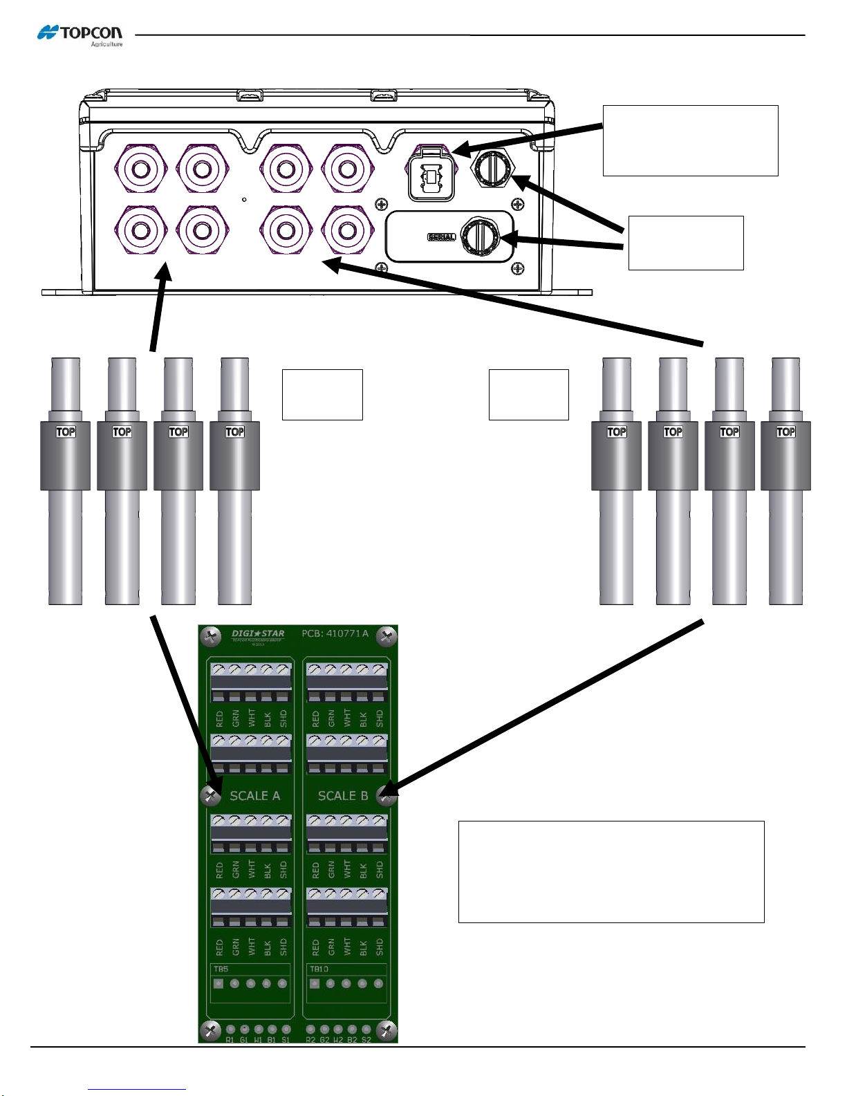
PCB AND WIRING CONNECTIONS
PCBA
RS232 COM1 & COM2, COM
Ground (current limited)
Load Cell connections
USB port
CAN2 port,
CAN2 Ground
(current limited)
Reset button
SLC/ Remote Port
(SPI bus - proprietary)
Power, CAN1/ ISOBUS,
CAN Ground (current limited)
ACC Power, Sensor Input, 3A Output
Single scale models: All 4 terminal
connections are SCALE A
Multi-scale models: Each terminal is
a different scale; A, B, C, D

D4204-EN Scale Link 2 Technical Manual 9
Deutsch Connector
Load Cell Connection
+8V Excitation
6 pin Deutsch Receptacle –Power + CAN1/ ISOBUS
1. +VIN System Input Voltage (Red)
2. CAN1 High (Yellow)
3. 0V System Ground (Black)
4. CAN1 Low (Green)
5. Plug
6. Plug
CAN connection is non-terminated. CANBUS
application requires external 120 ohm termination.
ISOBUS application requires external active bus
termination per ISOBUS standards.
0V Excitation
- Signal
Shield/ Ground
Gray
Black
Blue
White
Brown
Load Cell Connections –On Board and M12 EZ Mates
+ Signal

10 Scale Link 2 Technical Manual D4204-EN
SLC2810 Remote Connection
Header Pinout:
8-7-6-5-4-3-2-1
SLC Remote Port –Proprietary SPI Bus
*Note: +V is fused at 750mA on this port

D4204-EN Scale Link 2 Technical Manual 11
Serial Port/ RS232 Connection
Input and Output Connections
Serial Port –Dual RS232 Ports with System Power
1. Brown +VIN
2. White TX1
3. Blue RX1
4. Black TX2
5. Gray COM 0V (*current limited)
6. Pink RX2
*For higher current loads using +VIN, move Gray wire
from COM 0V (current limited) to 0V (not limited).
Set baud rate and parity with Menu 2 settings. See ‘Basic Serial Settings’
at back of manual or D4020 DAN list for settings details.
3 cable options available to fit this M12 port:
1. 410840 M12 to pigtail –wire your own cable
2. 410818 M12 to AMP –COM1 & 2 for ERM/ DS SER port
3. 411015 M12 to DB9 –PC connection with COM1
3
4
5
6
2
1
Input/ Output Connections –On Board, accessible through ACC port strain relief
+VIN –System voltage, non-fused
0V –System ground, non-fused
IP1 –Remote Input 1; active high, low or pulsed based on settings
OP1 –Output Control FET; 3A continuous at system voltage
0V –System ground, non-fused

12 Scale Link 2 Technical Manual D4204-EN
SYSTEM CONFIGURATIONS
Small box, single 4 Terminal Block scale (410614 SL2110 shown)
4 load cells direct wire into box
Accessory port for options such
as remote input & output control
ISOBUS/ CAN port for
power and primary
communication
Wire in J-boxes to handle additional
load cells up to a total of 16
Single scale models (as shown): All
4 terminal connections are SCALE A
Multi-scale models: Each terminal is
a different scale; A, B, C, D

D4204-EN Scale Link 2 Technical Manual 13
Small box, quad platform M12 EZMate scale (410624 SL2140 shown)
Accessory port for
options such as remote
input & output control
ISOBUS/ CAN port for
power and primary
communication
Scale A
4 bars
Scale B
4 bars
Scale C
4 bars
Scale D
4 bars
SLC remote
& Serial Ports
M12 jumper cables
are used between
SL2 and J-blocks
14 Scale Link 2 Technical Manual D4204-EN
Large box, dual platform 8 Terminal Block scale (410619 SL2220 shown)
ISOBUS/ CAN port for
power and primary
communication
SLC Remote
& Serial Port
Scale A
4 bars
Scale B
4 bars
Single scale models: All 8 terminal
connections are SCALE A
Dual-scale models (as shown): Each 4
terminal section is a different scale; A & B

D4204-EN Scale Link 2 Technical Manual 15
More system configurations and options are available. Complete systems are configured based on similar box
designs below. Mounting brackets are available for easier installation. Contact Topcon for more details.
Small Box designs
M12 or strain reliefs/ direct wire
Single scale or up to 4 platforms
Up to 4 load cell connections
With or without cables and
connectors
Large Box designs
Strain reliefs/ direct wire
Single scale or Dual scale
Up to 10 load cell connections

16 Scale Link 2 Technical Manual D4204-EN
OPERATION REFERENCES
Using SL2 with SLC2810 Remote
Refer to D4195 SLC2810 Operation Manual for detailed operation, and D4020 Direct Access Numbers for the most
current DAN codes. Some specific operations and features are described below.
Using SL2 with Universal Terminal (UT)
Refer to D4196 SL2 ISO Operators Manual for detailed UT operation, and D4020 Direct Access Numbers for the
most current DAN codes. Some specific operations and features are described below.
*When the SL2 is connected to a UT for the first time, it may take several minutes to load the SL2 mask.
Updating software, storing and loading settings
Refer to D4206 Software Guide for details. Works best with SLC2810, but is possible to do with UT.
*Always save all settings and data first prior to performing any software updates!
While the SL2 is designed to save and restore settings automatically, significant software revision changes may
result in lost settings when not stored ahead of time. The SL2 is also designed to return to a functioning default
setup in case settings are lost, which allows the system to run on both SLC2810 and ISOBUS mask platforms,
without requiring return to a service center.
-Put S19 software file on blank USB (if performing software update). Must be title of ‘image.s19’. Add object pool
file if the mask is also to be updated.
-Remove SL2 cover, insert USB.
-Save Settings to USB. SVSET in ‘Select’ menu, USB down arrow on UT, or use DAN 8713.
-Press reset button on SL2 board, software will now load. May take several minutes.
-Unplug SL2 power for 10 seconds, then plug back in. May take up to 2 minutes to come up on UT.
-UT screen and/ or SLC2810 should now be up in weighing mode.
-Remove USB and replace cover.
-If settings did not automatically load, use LD SET in ‘Select’ menu, USB up arrow on UT, or DAN 8714.

D4204-EN Scale Link 2 Technical Manual 17
Selecting the active scale (multi-scale models only)
SLC2810: Press ‘SELECT’ until SCALE is displayed. Press ‘FUNCTION’ to select available scales.
UT: On the UT screen, touch the scale that you want selected.
Changing Setup & Calibration Numbers
SLC2810: Select the active scale (multi-scale units). Use DAN codes and ‘SELECT’ key to adjust counts, weigh
method, setup, calibration, etc. DAN 8711 and 8712 used for entry of known setup and calibration numbers.
UT: Touch the spinning arrow button above the home key . Touch the ‘Select Scale’ box and choose the scale
to update (multi-scale units). Change Scale ID, Units, Setup Number, Cal Number, or Display Counts as needed.
18 Scale Link 2 Technical Manual D4204-EN
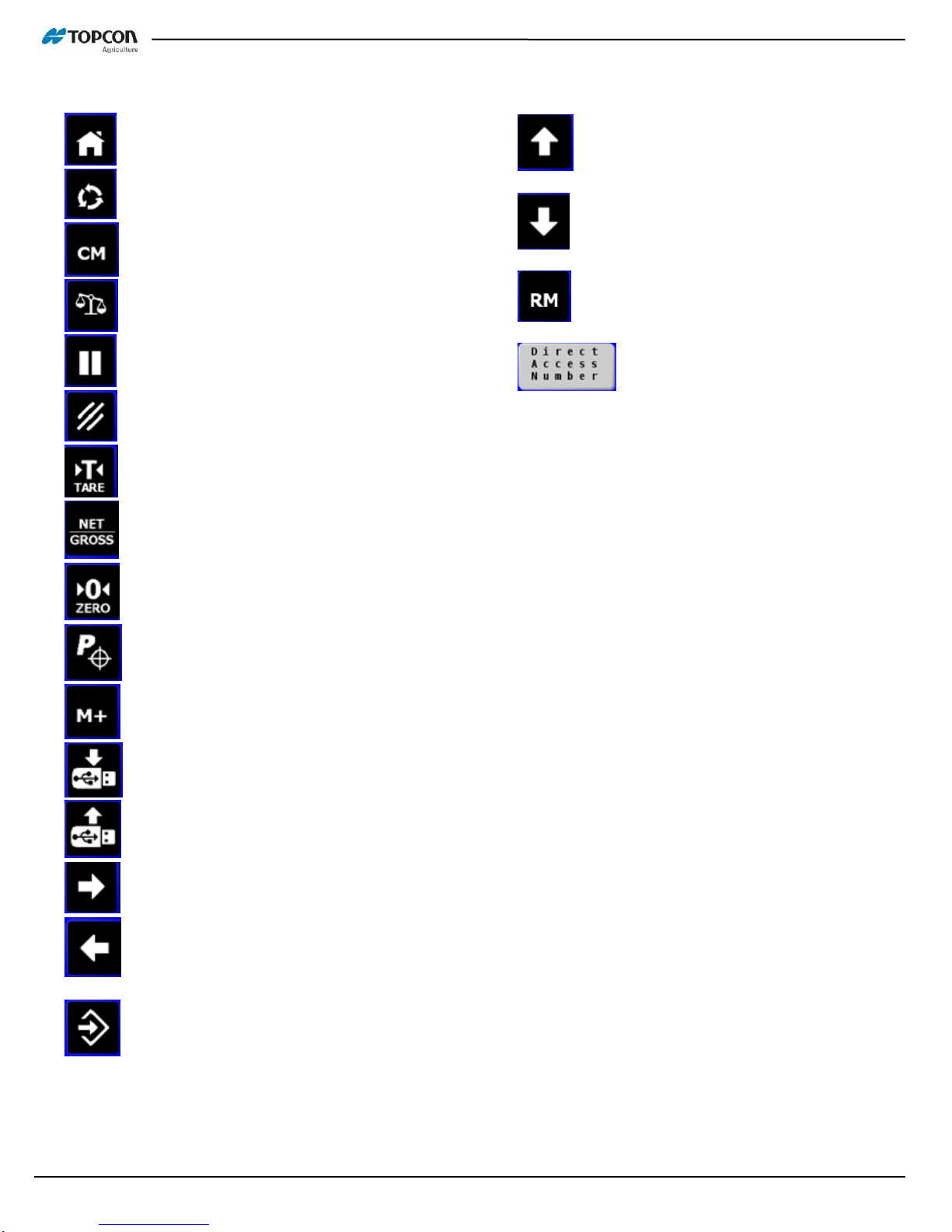
Keys Used on Scale Link ISO Terminal
--HOME:
--ENTER SETUP SCREENS:
--CLEAR MEMORY:
--CONFIGURE MAIN SCREEN LAYOUT:
--HOLD:
--CANCEL:
--TARE:
--NET/GROSS:
--ZERO:
--PRESET:
--ADD TO MEMORY:
--SAVE TO USB:
--LOAD FROM USB:
--MOVE TO RIGHT:
--MOVE TO LEFT:
--ENTER:
--MOVE UP:
--MOVE DOWN:
--RECALL MEMORY:
--TO ENTER DIRECT
ACCESS NUMBERS:

D4204-EN Scale Link 2 Technical Manual 19
Scale Link Control Overview
1
2
8
3
4
5
6
7
10
11
12
13
14
15
16
- Pause
- Cancel
- Enter setup screens
- Temporary zero (Net Mode)
- Toggles between Net and Gross Weights
- Press and hold for 3 seconds to zero balance indicator.
- Enter preset weight
- Add to memory
1
2
3
4
5
6
7
8

20 Scale Link 2 Technical Manual D4204-EN
Summed Weight –Total weight of scale A+B+C+D
Scale A –Gross Weight
Scale B –Gross Weight
Scale C –Gross Weight
Scale D –Gross Weight
Mask Number –Mask version that is applied to screen
Software Version –Displays current software version
Hardware Detected –Displays which hardware is recognized by the SL2
9
10
11
12
13
14
15
16
This manual suits for next models
5
Table of contents
Other Digistar Accessories manuals


 user manual")


