manuals.online logo
Brands
  1. Home
  2. •
  3. Brands
  4. •
  5. SICK
  6. •
  7. Accessories
  8. •
  9. SICK PowerProx WTT12L User manual

SICK PowerProx WTT12L User manual

Quickstart
EN/IEC 60825-1:2014
Laser
1
Maximale Pulsleistung: < 250 mW
Impulsdauer: 4 ns
Wellenlänge: 658 nm
Entspricht 21 CFR 1040.10
und 1040.11 mit Ausnahme von
Abweichungen nach
Laser-Hinweis 56, 8. Mai 2019
LASERKLASSE 1
2006/42/EC
NO
SAFETY
UL Environmental Rating: Enclosure Type 1.
8018110:
Q U I C K S T A R T
en
These instructions are only valid in connection with the 8018110 operating
instructions. You can find the operating instructions at www.sick.com.
de
Diese Anleitung ist ausschließlich in Verbindung mit der Betriebsanleitung
(8018110) gültig. Die Betriebsanleitung finden Sie unter www.sick.com.
it
Le presenti istruzioni sono valide solo in abbinamento alle istruzioni per l'uso
(8018110). Le istruzioni per l’uso sono a disposizione su www.sick.com.
fr
Cette notice n’est valable qu’avec la notice d'instruction (8018110). Elle est
disponible sur le site Internet www.sick.com.
es
Estas instrucciones solo son válidas junto con las instrucciones de uso
(8018110). Puede encontrar las instrucciones de uso en www.sick.com.
zh
本指南仅在结合使用操作指南 (8018110) 的情况下有效。查看操作指南可访
问 www.sick.com 网页。
1 Operating and status indicators
Bedien- und Anzeigeelemente Elementos de mando y visualización
Elementi di comando e di visualizzazione 操作及显示元件
Éléments de commande et d'affichage
-xxxx2 / -xxxx4 -xxxx1 -xxxx3 / -xxxx7 -xxxx6 / -xxxx8
1
5
2
34
1Single teach-in pushbutton / Einfach-Teach-in-Taste / Pulsante Teach-in sem‐
plice / Touche d'apprentissage simple / Botón de aprendizaje (Teach-in) sim‐
ple / 单示教按键
2Potentiometer / Potentiometer / Potenziometro /Potentiomètre / Potenció‐
metro / 电位计
3Potentiometer / LED indicator yellow: status of received light beam / Poten‐
tiometer/LED-Anzeige gelb: Status des empfangenen Lichtstrahls / Potenz‐
iometro/indicatore a LED giallo: stato del raggio luminoso ricevuto / Poten‐
tiomètre/LED d’état jaune: état du faisceau lumineux reçu / Potenció‐
metro/Indicador LED amarillo: estado del haz de luz recibido / 电位计/黄色
状态 LED:接收的光束状态
4Potentiometer / LED Indicators (green): Power on / Potentiometer / LED-
Anzeigen (grün): Power on /Potenziometro/indicatori LED (verde): Power on /
Potentiomètre/Affichages LED (verts): Power on / Potenciómetro/Indicadores
LED (verde): Power on / 电位计/LED 指示灯(绿色): Power On(电源接通)
5Potentiometer / LED indicator yellow: status of received light beam / Poten‐
tiometer/LED-Anzeige gelb: Status des empfangenen Lichtstrahls / Potenz‐
iometro/indicatore a LED giallo: stato del raggio luminoso ricevuto / Poten‐
tiomètre/LED d’état jaune: état du faisceau lumineux reçu / Potenció‐
metro/Indicador LED amarillo: estado del haz de luz recibido / 电位计/黄色
状态 LED:接收的光束状态
2 Mounting
Montage Montaje
Montaggio 安装
Montage
en
Mount the sensorusing a suitable mounting bracket (see the SICK range of
accessories).
Note the sensor's maximum permissible tightening torque of 0.8 Nm.
Note the preferred direction of the object relative to the sensor [see E].
de
Den Sensor an einen geeigneten Befestigungswinkel montieren (siehe SICK-Zube‐
hör-Programm).
Maximal zulässiges Anzugsdrehmoment des Sensors von 0.8 Nm beachten.
Vorzugsrichtung des Objektes zum Sensor beachten [vgl. E].
it
Montare il sensore su un punto di fissaggio adatto (vedi il programma per acces‐
sori SICK).
Rispettare il momento torcente massimo consentito del sensore di 0.8 Nm.
Rispettare la direzione preferenziale dell'oggetto in relazione al sensore [cfr. E].
fr
Monter le capteur sur une équerre de fixation adaptée (voir la gamme d'accessoi‐
res SICK).
Respecter le couple de serrage maximum autorisé du capteur de 0.8 Nm
Tenir compte de la direction préférentielle de l'objet par rapport au capteur [voir
E].
es
Montar el sensor en una escuadra de fijación adecuada (véase el programa de
accesorios SICK).
Respetar el par de apriete máximo admisible del sensor de 0.8 Nm.
Respetar la orientación preferente del objeto con respecto al sensor. [véase fig.
E].
zh
将传感器安装在合适的安装托架上(参见 SICK 附件说明书)。
注意传感器的最大允许拧紧扭矩为 0.8 Nm。
以传感器为参照物,注意物体的优先方向 [参照 E]。
3 Electrical installation
Elektrische Installation Instalación eléctrica
Installazione elettrica 电气安装
Installation électrique
UB: 10 ... 30 V DC
en
Operation in standard I/O mode:
The sensors must be connected in a voltage-free state (Uv = 0 V). The information
in the graphics [B] must be observed, depending on the connection type:
– Male connector connection: pin assignment
– Cable: core color
de
Betrieb im Standard I/O-Modus:
Anschluss der Sensoren muss spannungsfrei (UV = 0 V) erfolgen. Je nach
Anschlussart sind die Informationen in den Grafiken [vgl. B] zu beachten:
– Steckeranschluss: Pinbelegung
– Leitung: Adernfarbe
it
Funzionamento in modalità I/O standard:
Il collegamento dei sensori deve avvenire in assenza di tensione (UV = 0 V). In
base al tipo di collegamento si devono rispettare le informazioni nei grafici [cfr. B]:
– Collegamento a spina: assegnazione pin
– Conduttore: colore filo
fr
Fonctionnement en mode I/O standard:
Le raccordement des capteurs doit s'effectuer hors tension (Uv = 0 V). Selon le
mode de raccordement, respecter les informations contenues dans les schémas
[B] :
– Raccordement du connecteur : affectation des broches
– Câble : couleur des fils
es
Funcionamiento en modo E/S estándar:
Los sensores deben conectarse sin tensión (UV = 0 V). Debe tenerse en cuenta la
información de las figuras [B] en función de cada tipo de conexión:
8026849.1D62/13.09.2022/de PowerProx - WTT12L | SICK 1
8026849.1D62/13.09.2022
www.sick.com
PowerProx - WTT12L
SICK AG
E
rwin-Sick-Straße 1
DE-79183 Waldkirch
– Conexión de enchufes: asignación de terminales
– Cable: color del hilo
zh
标准 I/O 模式下的运行:
必须在无电压状态 (UV = 0 V) 连接传感器。依据不同连接类型,注意图 [参照
B] 中的信息:
– 插头连接:引线分配
– 电缆:芯线颜色
WTT12L- WTT12LC-
B2xx1/B2xx2
B3xx1/B3xx2
B1xx1/B1xx2
B2xx6/B2xx3
B3xx6/B3xx3
B1xx6/B1xx3
B2xx8/B2xx7
B3xx8/B3xx7
B1xx87B1xx7
B2xx4/B3xx4
B1xx4 B2xx3/B3xx3
B1xx3
(1) = BN + (L+)
(2) = WH QQ2QMFin
(3) = BU - (M)
(4) = BK Q Q1Q Q1/C
(5) = GR Test L/D Teach MFout
4 Commissioning
Inbetriebnahme Puesta en servicio
Messa in servizio 调试
Mise en service
4.1 Alignment
Ausrichtung Alineación
Orientamento 校准
Alignement
Visible red light / sichtbares Rotlicht / Luz roja visible / Lumière rouge visible /
luce rossa visibile / 可见红光
1.
2.
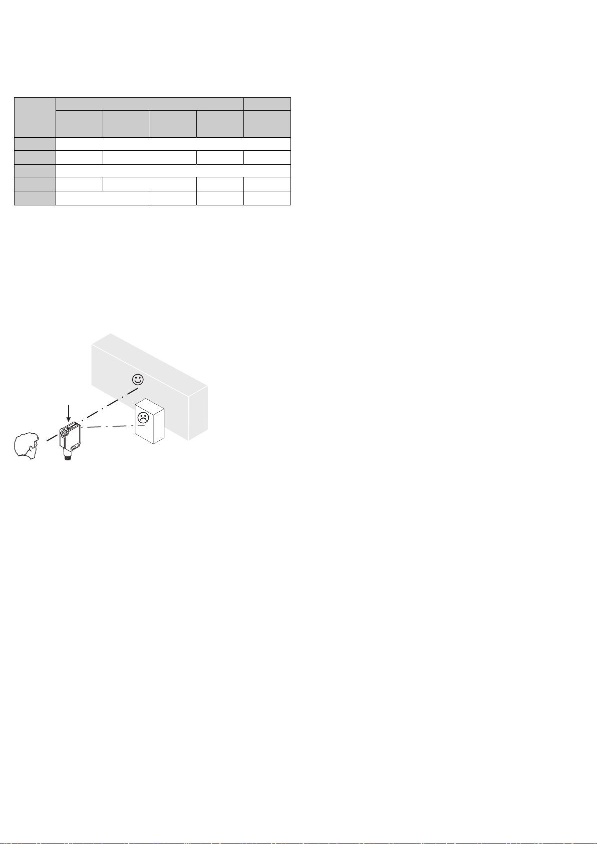
4.2 Sensing range setting
Einstellung Schaltabstand Ajuste de la distancia de conmutación
Regolazione distanza di lavoro 触发感应距离设置
Réglage distance de commutation
en
Sensor with potentiometer:
The sensing range is adjusted with the potentiometer (type: 4 rotations). Clock‐
wise rotation: sensing range increased; counterclockwise rotation: sensing range
reduced. We recommend placing the switching state in the object, e. g., see
graphic E. Once the sensing range has been adjusted, the object is removed from
the path of the beam, which causes the background to be suppressed and the
switching output to change (see graphic C).
Sensor with teach-in button:
The sensing range is adjusted by pressing the teach-in button. Do not operate the
teach-in button using sharp objects. We recommend placing the switching state in
the object, e. g., see graphic E. Once the sensing range has been adjusted, the
object is removed from the path of the beam, which causes the background to be
suppressed and the switching output to change (see graphic C).
Please refer to the enclosed operating instructions for the IO-Link photoelectric
sensor for information about adjusting the IO-Link sensing range.
The sensor is adjusted and ready for operation. Refer to graphics C and E to check
the function. If the switching output fails to behave in accordance with graphic C,
check application conditions. See section Fault diagnosis.
de
Sensor mit Potentiometer:
Mit dem Potentiometer (Art: 4 Umdrehungen) wird der Schaltabstand eingestellt.
Drehung nach rechts: Erhöhung des Schaltabstandes, Drehung nach links: Verrin‐
gerung des Schaltabstandes. Wir empfehlen, den Schaltabstand in das Objekt zu
legen, z. B. siehe Grafik E. Nachdem der Schaltabstand eingestellt worden ist,
das Objekt aus dem Strahlengang entfernen, der Hintergrund wird dabei ausgebl‐
endet und der Schaltausgang ändert sich (siehe Grafik C).
Sensor mit Teach-in-Taste:
Durch Drücken der Teach-in-Taste wird der Schaltabstand eingestellt. Teach-in-
Taste nicht mit spitzen Gegenständen betätigen. Wir empfehlen, den Schaltab‐
stand in das Objekt zu legen, z. B. siehe Grafik E. Nach dem der Schaltabstand
eingestellt worden ist, das Objekt aus dem Strahlengang entfernen, der Hinter‐
grund wird dabei ausgeblendet und der Schaltausgang ändert sich (siehe Grafik
C).
Einstellung des Schaltabstandes über IO-Link bitte der beiliegenden Betriebsan‐
leitung IO-Link Photoelectric sensors entnehmen.
Sensor ist eingestellt und betriebsbereit. Zur Überprüfung der Funktion Grafik C
und E heranziehen. Verhält sich der Schaltausgang nicht gemäß Grafik C, Einsatz‐
bedingungen prüfen. Siehe Abschnitt Fehlerdiagnose.
it
Sensore con potenziometro:
Con il potenziometro (tipo: 4 rotazioni) viene regolata la distanza di commuta‐
zione. Rotazione verso destra: innalzamento della distanza di commutazione,
rotazione verso sinistra: riduzione della distanza di commutazione. Si consiglia di
fissare la distanza di commutazione nell'oggetto, ad es. vedi grafico E. Dopo l'im‐
postazione della distanza di commutazione, allontanare l'oggetto dalla traiettoria
del raggio, lo sfondo viene quindi soppresso e l'uscita di commutazione cambia
(vedi grafico C).
Sensore con tasto Teach-in:
Premendo il tasto Teach-in viene impostata la distanza di commutazione. Non
azionare il tasto Teach-in con oggetti appuntiti. Si consiglia di fissare la distanza
di commutazione nell'oggetto, ad es. vedi grafico E. Dopo l'impostazione della
distanza di commutazione, allontanare l'oggetto dalla traiettoria del raggio, lo
sfondo viene quindi soppresso e l'uscita di commutazione cambia (vedi grafico C).
Per l'impostazione della distanza di commutazione tramite IO-Link , consultare le
istruzioni d'uso allegate "IO-Link Photoelectric sensors".
Il sensore è impostato e pronto per il funzionamento. Per verificare il funziona‐
mento, osservare i grafici C e E. Se l'uscita di commutazione non si comporta
conformemente al grafico C, verificare le condizioni d'impiego. Vedi paragrafo
diagnostica delle anomalie.
fr
Capteur avec potentiomètre :
La portée se règle avec le potentiomètre (réf.: 4 tours). Rotation vers la droite :
augmentation de la portée, rotation vers la gauche : réduction de la portée. Nous
recommandons de régler la portée sur l'objet, par ex. voir schéma E. Après le
réglage de la portée, retirer l'objet de la trajectoire du faisceau, ce qui élimine
l'arrière-plan et fait basculer la sortie de commutation (voir le schéma C).
Capteur avec touche apprentissage :
Appuyer sur la touche apprentissage pour régler la portée. Ne pas appuyer sur
la touche apprentissage avec des objets pointus. Nous recommandons de régler
la portée sur l'objet, par ex. voir schéma E. Après le réglage de la portée, retirer
l'objet de la trajectoire du faisceau, ce qui élimine l'arrière-plan et fait basculer la
sortie de commutation (voir le schéma C).
Pour régler la portée via une liaison IO-Link, consulter la notice d'instruction
"IO-Link Photoelectric sensors ".
Le capteur est réglé et prêt à être utilisé. Pour contrôler le fonctionnement,
utiliser les schémas C et E. Si la sortie de commutation ne se comporte pas
comme indiqué sur le schéma C, vérifier les conditions d'utilisation. Voir la section
consacrée au diagnostic.
es
Sensor con potenciómetro:
Con el potenciómetro (tipo: 4 revoluciones) se ajusta la distancia de conmuta‐
ción. Giro hacia la derecha: aumenta la distancia de conmutación; giro hacia
la izquierda: se reduce la distancia de conmutación. Recomendamos poner la
distancia de conmutación en el objeto, p. ej., véase figura E. Una vez ajustada la
distancia de conmutación, retirar el objeto de la trayectoria del haz, el fondo se
suprime y la salida conmutada cambia (véase Figura C).
Sensor con botón de aprendizaje:
Pulsando el botón de aprendizaje se ajusta la distancia de conmutación. No
accione el botón de aprendizaje con objetos puntiagudos. Recomendamos poner
la distancia de conmutación en el objeto, p. ej., véase Figura E. Una vez ajustada
la distancia de conmutación, retirar el objeto de la trayectoria del haz, el fondo se
suprime y la salida conmutada cambia (véase Figura C).
El ajuste de la distancia de conmutación a través de IO-Link lo puede consultar
en las instrucciones de uso para sensores fotoeléctricos IO-Link adjuntas.
El sensor está ajustado y listo para su uso. Para verificar el funcionamiento,
véanse las figuras C y E Si la salida conmutada no se comporta según la figura
C, comprobar las condiciones de aplicación. Véase la sección "Diagnóstico de
fallos".
zh
配电位计的传感器:
使用电位计(型号:4 圈) 设置开关距离。向右旋转:提高开关距离,向左旋
转:降低开关距离。我们建议开关距离应涵盖物体;例如,参见图 E。开关距
离设置完成后,将物体从光路中移除,同时,将抑制背景并改变输出信号开关
装置(参见图 C)。
带示教按键的传感器:
通过按下示教按键可设置开关距离。不得使用尖锐物操作示教按键。我们建议
开关距离应涵盖物体;例如,参见图 E。开关距离设置完成后,将物体从光路
中移出,同时,将抑制背景并改变输出信号开关装置(参见图 C)。
通过 IO-Link 设置开关距离时,请参阅随附的 IO-Link 光电传感器使用说明
书。
传感器已设置并准备就绪。参照图 C 和 E 检查功能。如果输出信号开关装置
的动作不符合图 C,则须检查使用条件。参见故障诊断章节。
8026849 / 13.09.2022/de WTT12L | SICK 2
–
+
Q1
Q1
Q1
Q1
5 Troubleshooting
Störungsbehebung Resolución de problemas
Eliminazione difetti 故障排除
Élimination des défauts
en
LED indicator/fault pattern Cause Measures
Green LED does not light up No voltage or voltage below
the limit values Check the power supply,
check all electrical connec‐
tions (cables and plug con‐
nections)
Voltage interruptions Ensure there is a stable
power supply without inter‐
ruptions
Sensor is faulty If the power supply is OK,
replace the sensor
Green LED lights up, no output
signal when object is detected Test input (Test) is not con‐
nected properly See the note on connecting
the TI
Green LED flashes IO-Link communication -
Switching outputs not accord‐
ing to graphic C IO-Link communication
Parameter settings made
manually, which deviate from
the standard
-
Initiate a factory reset. The
switching outputs are reset to
factory settings.
Yellow LEDs flash at the same
time The sensor is not ready for
operation. The sensor will be
in the warming-up phase at
low ambient temperatures.
The sensor will have shut
down at excessively high
ambient temperatures.
At low ambient temperatures,
wait until the sensor has
warmed up. Ensure the sen‐
sor cools down at excessively
high ambient temperatures.
Yellow LED flashes (only
briefly) Teach-in mode Check the teach-in mode
Yellow LED lights up, no object
in the path of the beam Distance between the sensor
and the background is too
short
Reduce the sensing range
Object is in the path of the
beam, yellow LED does not
light up
Distance between the sensor
and the object is too long or
sensing range is set too short
Increase the sensing range
de
LED / Fehlerbild Ursache Maßnahme
Grüne LED leuchtet nicht. Keine Spannung oder Span‐
nung unterhalb der Grenz‐
werte
Spannungsversorgung prü‐
fen, den gesamten elektri‐
schen Anschluss prüfen (Lei‐
tungen und Steckerverbin‐
dungen)
Spannungsunterbrechungen Sicherstellen einer stabilen
Spannungsversorgung ohne
Unterbrechungen
Sensor ist defekt Wenn Spannungsversorgung
in Ordnung ist, dann Sensor
austauschen
grüne LED leuchtet, kein Aus‐
gangssignal bei Objektdetek‐
tion
Testeingang (Test) ist nicht
korrekt angeschlossen Siehe Hinweis für Anschluss
des TE
Grüne LED blinkt. IO-Link Kommunikation -
Digitalausgänge nicht nach
Grafik IO-Link Kommunikation
Manuell vorgenommene,
vom Standard abweichende,
Parametereinstellungen
-
Factory reset auslösen. Die
Digitalausgänge werden wie‐
der auf Werkseinstellung
zurückgesetzt.
Gelbe LEDs blinken synchron Sensor ist nicht betriebsbe‐
reit. Bei tiefen Umgebungs‐
temperaturen befindet sich
der Sensor in der Aufwärm‐
phase. Bei zu hohen Umge‐
bungstemperaturen hat sich
der Sensor abgeschaltet.
Bei tiefen Umgebungstempe‐
raturen warten, bis sich der
Sensor aufgewärmt hat. Bei
zu hohen Umgebungstempe‐
raturen für Abkühlung sorgen
Gelbe LED blinkt (nur kurz). Teach-Modus Teach-Modus überprüfen
Gelbe LED leuchtet, kein
Objekt im Strahlengang. Abstand zwischen Sensor
und Hintergrund ist zu gering Schaltabstand verringern
Objekt ist im Strahlengang.
Gelbe LED leuchtet nicht. Abstand zwischen Sensor
und Objekt ist zu groß oder
Schaltabstand ist zu gering
eingestellt
Schaltabstand vergrößern
it
Indicatore LED / figura di
errore Causa Provvedimento
Il LED verde non si accende nessuna tensione o tensione
al di sotto del valore soglia Verificare la tensione di ali‐
mentazione e/o il collega‐
mento elettrico
Interruzioni di tensione Assicurarsi che ci sia un'ali‐
mentazione di tensione sta‐
bile
Il sensore è guasto Se l'alimentazione di ten‐
sione è regolare, allora chie‐
dere una sostituzione del
sensore
il LED verde si accende,
nessun segnale in uscita al
momento di rilevamento del‐
l'oggetto
L'entrata di prova (Test) non
è collegata correttamente Vedi le indicazioni per il colle‐
gamento della TE
Il LED verde lampeggia Comunicazione IO-Link -
Uscite di commutazione non
conformi al grafico C Comunicazione IO-Link
impostazione dei parametri
regolata manualmente che si
differenzia dallo standard
-
Azionare factory reset. Le
uscite di commutazione ven‐
gono riportate alle imposta‐
zioni di fabbrica prima della
fornitura.
i LED gialli lampeggiano in
maniera sincrona Il sensore non è pronto
per il funzionamento. In
presenza di basse tempera‐
ture ambientali il sensore
è in fase di riscaldamento.
In presenza di temperature
ambientali elevate il sensore
si è disattivato.
In presenza di basse tempe‐
rature ambientali attendere
che il sensore si sia riscal‐
dato. In presenza di tempera‐
ture ambientali elevate prov‐
vedere al raffreddamento
il LED giallo lampeggia (solo
brevemente) Modalità Teach Verificare la modalità Teach
il LED giallo si accende, nes‐
sun oggetto nella traiettoria
del raggio
La distanza tra sensore e
sfondo è inferiori alle capa‐
cità di funzionamento
Diminuire la distanza di com‐
mutazione
L'oggetto è nella traiettoria
del raggio, il LED giallo non si
accende
La distanza tra sensore e
oggetto è troppo grande o
la distanza di commutazione
ha un'impostazione troppo
bassa
Aumentare la distanza di
commutazione
8026849 / 13.09.2022/de WTT12L | SICK 3
fr
LED d'état / image du défaut Cause Mesure
La LED verte ne s'allume pas Pas de tension ou tension
inférieure aux valeurs limites Contrôler l'alimentation élec‐
trique, contrôler tous les
branchements électriques
(câbles et connexions)
Coupures d'alimentation
électrique S'assurer que l'alimentation
électrique est stable et inin‐
terrompue
Le capteur est défectueux Si l'alimentation électrique
est en bon état, remplacer le
capteur
La LED verte s'allume, pas
de signal de sortie en cas de
détection d'objet
L'entrée test (Test) n'est pas
correctement raccordée Voir les informations sur le
raccordement de l'entrée
test
La LED verte clignote Communication IO-Link -
Sorties de commutation non
conformes au schéma C Communication IO-Link
Réglages des paramètres
effectués manuellement,
divergeant du standard
-
Déclencher le réarmement
de fabrication. Les sorties de
commutation sont remises
sur le réglage d'usine.
Les LED jaunes clignotent
simultanément. Le capteur n'est pas opéra‐
tionnel. Lorsque la tempéra‐
ture ambiante est basse, le
capteur se trouve en phase
de réchauffement. Lorsque
la température ambiante est
trop élevée, le capteur s'est
désactivé.
Lorsque la température
ambiante est basse, patien‐
ter jusqu'à ce que le capteur
se soit réchauffé. Lorsque
la température ambiante est
élevée, veiller au refroidisse‐
ment.
La LED jaune clignote (briève‐
ment) Mode apprentissage Contrôler le mode apprentis‐
sage
La LED jaune s'allume, pas
d'objet dans la trajectoire du
faisceau
La distance entre le capteur
et l'arrière-plan est trop fai‐
ble
Réduire la portée
L'objet est dans la trajectoire
du faisceau, la LED jaune ne
s'allume pas
La distance entre le capteur
et l'objet est trop grande ou
la portée est trop faible
Augmenter la portée
es
LED indicador / imagen de
error Causa Acción
El LED verde no se ilumina Sin tensión o tensión por
debajo de los valores límite Comprobar la fuente de ali‐
mentación, comprobar toda
la conexión eléctrica (cables
y conectores)
Interrupciones de tensión Asegurar una fuente de ali‐
mentación estable sin inte‐
rrupciones de tensión
El sensor está defectuoso Si la fuente de alimentación
no tiene problemas, cambiar
el sensor
El LED verde se ilumina, no
hay señal de salida cuando se
detecta un objeto
La entrada de prueba
(Test) no está correctamente
conectada
Ver indicaciones para conec‐
tar la entrada de prueba (TE)
El LED verde parpadea Comunicación con sistema
IO-Link -
Las salidas conmutadas no
corresponden a la figura C Comunicación con sistema
IO-Link
Configuración manual de
parámetros que difieren del
estándar
-
Restablecer valores de
fábrica. Las salidas conmu‐
tadas vuelven a los ajustes
de fábrica.
Los LED amarillos parpadean
simultáneamente El sensor no está listo para
su uso. Si la temperatura
ambiente es baja, el sensor
se encuentra en la fase de
calentamiento. Si la tempe‐
ratura ambiente es alta, el
sensor se ha desconectado.
Si la temperatura ambiente
es baja, esperar hasta que el
sensor se haya calentado. Si
la temperatura ambiente es
demasiado alta, refrigerar
El LED amarillo parpadea
(solo brevemente) Modo de aprendizaje (Teach) Comprobar el modo de
aprendizaje
El LED amarillo se ilumina, no
hay ningún objeto en la tra‐
yectoria del haz
La distancia entre el sensor y
el fondo es insuficiente Reducir la distancia de con‐
mutación
El objeto se encuentra en la
trayectoria del haz, el LED
amarillo no se ilumina
La distancia entre el sensor y
el objeto es excesiva o la dis‐
tancia de conmutación ajus‐
tada es insuficiente
Aumentar la distancia de
conmutación
zh
LED 指示灯 / 故障界面 原因 措施
绿色 LED 未亮起 无电压或电压低于极限值 检查电源,检查整体电气连接
(导线和插头连接)
电压中断 确保电源稳定无中断
传感器损坏 如果电源正常,则更换传感器
绿色 LED 亮起,探测物体时无
输出信号
未正确连接测试输入端 (Test) 参见 TE 的连接提示
绿色 LED 闪烁 IO-Link 通信 -
LED 指示灯 / 故障界面 原因 措施
不符合图 C 的开关输出端 Q IO-Link 通信
手动执行,可标准有所偏差的
参数设置
-
启用恢复出厂设置。将开关输
出端重新设置为出厂设置。
黄色 LED 同步闪烁。 传感器未准备就绪。环境温度
低时传感器处于预热阶段。环
境温度高时传感器自行关闭。
环境温度低时请等待,至传感
器完成预热。环境温度高时请
降温。
黄色 LED 闪烁(非常短暂) 示教模式 检查示教模式
黄色 LED 亮起,光路中无物体 传感器和背景之间的间距过小 降低开关距离
光路中有物体,黄色 LED 未亮
起
传感器和物体之间的间距过大
或开关距离设置的过小
增大开关距离
8026849 / 13.09.2022/de WTT12L | SICK 4

Other manuals for PowerProx WTT12L

5

This manual suits for next models

24

Other SICK Accessories manuals

SICK WSE9-3P User manual

SICK

SICK WSE9-3P User manual

SICK WL34 User manual

SICK

SICK WL34 User manual

SICK WTB26 User manual

SICK

SICK WTB26 User manual

SICK DT50-2 Pro User manual

SICK

SICK DT50-2 Pro User manual

SICK WTT190LC-B2233A00 User manual

SICK

SICK WTT190LC-B2233A00 User manual

SICK GL6 Series User manual

SICK

SICK GL6 Series User manual

SICK LMS4000 User manual

SICK

SICK LMS4000 User manual

SICK CQF16 User manual

SICK

SICK CQF16 User manual

SICK AS30 Prime Edge User manual

SICK

SICK AS30 Prime Edge User manual

SICK WT34 Series User manual

SICK

SICK WT34 Series User manual

SICK WT18-3 User manual

SICK

SICK WT18-3 User manual

SICK SIM1004 User manual

SICK

SICK SIM1004 User manual

SICK RS25 Series User manual

SICK

SICK RS25 Series User manual

SICK DME4000 User manual

SICK

SICK DME4000 User manual

SICK RFU61 Series User manual

SICK

SICK RFU61 Series User manual

SICK Lector620 User manual

SICK

SICK Lector620 User manual

SICK DL100 Pro User manual

SICK

SICK DL100 Pro User manual

SICK KTS-WB61141142 Series User manual

SICK

SICK KTS-WB61141142 Series User manual

SICK Z18 SimpleSense User manual

SICK

SICK Z18 SimpleSense User manual

SICK DL100 Pro User manual

SICK

SICK DL100 Pro User manual

SICK WS24-2 Series User manual

SICK

SICK WS24-2 Series User manual

SICK JEF300 Manual

SICK

SICK JEF300 Manual

SICK MLS User manual

SICK

SICK MLS User manual

SICK TiM1 Series User manual

SICK

SICK TiM1 Series User manual

Popular Accessories manuals by other brands

Hitachi S21 instruction manual

Hitachi

Hitachi S21 instruction manual

Philips EasyAir SNS410 MC Design-in guide

Philips

Philips EasyAir SNS410 MC Design-in guide

Philips DLA67020D brochure

Philips

Philips DLA67020D brochure

TriangleTube PSRKIT77 manual

TriangleTube

TriangleTube PSRKIT77 manual

WIKA MH-4-CAN Special Documentation

WIKA

WIKA MH-4-CAN Special Documentation

Siemens QFA2000 user guide

Siemens

Siemens QFA2000 user guide

RCA HSDB2 installation guide

RCA

RCA HSDB2 installation guide

teutonia PICK UP operating instructions

teutonia

teutonia PICK UP operating instructions

Dometic TROPICOOL TCX07 operating manual

Dometic

Dometic TROPICOOL TCX07 operating manual

Crow EDS-2000AM installation instructions

Crow

Crow EDS-2000AM installation instructions

Woody Valley Wani 3 manual

Woody Valley

Woody Valley Wani 3 manual

Tascam US-2000 owner's manual

Tascam

Tascam US-2000 owner's manual

PRESONUS AudioBox iTwo Series HOOK-UP GUIDE

PRESONUS

PRESONUS AudioBox iTwo Series HOOK-UP GUIDE

AQUANTIS Moisture-Sense user guide

AQUANTIS

AQUANTIS Moisture-Sense user guide

Datalogic Smart-VS Product reference guide

Datalogic

Datalogic Smart-VS Product reference guide

Evenflo Stroller Child Snack Tray manual

Evenflo

Evenflo Stroller Child Snack Tray manual

Rittal SK 3303.470 Assembly and operating instructions

Rittal

Rittal SK 3303.470 Assembly and operating instructions

Mircom MIX-FC351AP Installation and maintenance instructions

Mircom

Mircom MIX-FC351AP Installation and maintenance instructions

manuals.online logo
manuals.online logoBrands
  • About & Mission
  • Contact us
  • Privacy Policy
  • Terms and Conditions

Copyright 2025 Manuals.Online. All Rights Reserved.