senva TG Series User manual

INSTALLATION INSTRUCTIONS
senvainc.com 1-866-660-8864 (F)1-503-296-2529 9290 SW Nimbus Ave. Beaverton Oregon 97008
TG SERIES
Analog CO/NO2 Sensor
LIMITATION OF LIABILITY
Senva’s liability, whether in contract, in tort, under any warranty, in negligence
or otherwise shall not exceed the amount of the purchase price paid by the
purchaser for the product. Under no circumstances shall Senva be liable for
special or consequential damages.
INSTALLATION
1. Locate sensor near trac areas, away from sources of
ventilation or drafts. One sensor per 5000-7500 square feet is
normally required.
2. Mount the sensor directly to conduit or fasten the unit
securely to the wall with the appropriate fasteners.
Recommended mounting height is 5 feet. Check with local
and state building codes to ensure mounting height is in
compliance.
3. Wire the sensor as required for your application:
SEL
INC
DEC
POWER
COMMON
FAN IN
FAN OUT
ALARM IN
ALARM OUT
OUTPUT 1
OUTPUT 2
F A
O1
O2
Senva recommends 14-24 AWG shielded twisted pair. For runs
over 200 feet use a minimum of 22 AWG.
4. Apply power. Sensor may require up to 2 minutes of warmup
time prior to displaying valid gas measurements.
• Only qualied trade installers should install, program, maintain and test
system incorporated therein. Installer is responsible for compliance of all
applicable codes.
• Read, understand, and follow instructions thoroughly.
• The unit and associated systems require routine test and maintenance
as prescribed in the TG Series User’s Manual section ‘Periodic Test and
Maintenance’
• Do not install in hazardous or classied locations.
• De-energize power supply prior to installation.
• CO/NO2 sensors should not be used as a substitute for proper installation,
use, or maintenance of CO/NO2 emitting equipment.
• This CO/NO2 sensor is designed to detect conditions that could result in
acute eects of carbon monoxide or nitrogen dioxide exposure. It will not fully
safeguard individuals with specic medical conditions. If in doubt, consult a
medical practitioner.
Analog Outputs
Output 1: 0-10V
Output 2: 0-10V
Output Channels
TGW-AC: CO = Output 1
TGW-AN: NO2 = Output 1
TGW-ACN: CO = Output 1
NO2 = Output 2
To change default settings, refer to the User’s Guide available
online at www.senvainc.com/TGUG
FACTORY DEFAULT SETTINGS
FEATURES
Visual/Audible Indicators - Standard LCD, LED indicators
(green, yellow, red), audible alarm.
Installation Flexibility - Dual outputs available that can be
programmed for CO, NO2, and internal enclosure temperature
signals. Programmable fan and alarm relays for occupant
warnings.
Daisy Chain Wiring - Supports parallel connection of multiple
sensor voltage outputs.
Dual Gas Monitoring - Measure CO, NO2 or both in one
compact product. Sensor can be added or replaced in the eld
for easy upgrade.
Easy Quick Start - TG Series has 3 Quick Start congurations
that modify fan and alarm relay settings to common ranges.
Faster Commissioning - Test Mode Quick Start conguration
lowers relay and alarm thresholds for faster eld
commissioning.
Stand Alone Controller - Wire one or more devices for direct
control of an exhaust fan or VFD without costly controller.
PRODUCT IDENTIFICATION
TGW-
Output Type
A = Analog
Gas Type
C = Carbon Monoxide (CO)
N = Nitrogen Dioxide (NO2)
CN = CO/NO2 Combination
Enclosure/Lid
Blank = Clear/Tinted
-S = Solid/Opaque
Output Gas Lid
Output Scaling
CO: 0-200ppm
NO2: 0-10ppm
Fan Relay Setpoint
CO: 25ppm
NO2: 1ppm
Alarm Relay Setpoint
CO: 100ppm
NO2: 3ppm
SUPPORTING DOCUMENTS
TG Series User’s Guide
www.senvainc.com/TGUG
• Periodic Test and Maintenance
• Device Conguration
• Diagnostic Codes
DANGER
WARNING
!
ONE SENSOR PER CONTROL LOOP
OPERATION
The following section details daisy chain wiring support, LCD
function, LED function, fan/alarm relay functions, and the
sensor element lifetime clock.
Daisy Chain Wiring
Both voltage outputs are internally equipped to permit parallel
connection of multiple sensor voltage outputs. Resulting
voltage will be the greater of all connected sensors.
LCD Function
The LCD rotates between readings for each gas type populated
on the board. Toggling can be modied using the TG Series
User’s Guide(1).
LED Function
The LED indicators track the fan and alarm relay thresholds.
LEDs will change state if either gas reaches the setpoint.
Green Normal readings below the fan setpoint
Yellow Warning level above the fan setpoint and below the
alarm setpoint
Red Alarm level above the alarm setpoint
Fan/Alarm Relay
If a device has both CO and NO2 gas sensors, then the relay(s)
will activate if either gas reaches the corresponding setpoint.
Status LED Fan Relay Alarm Relay Buzzer
O - Closed Closed Silent
Below Fan Setpoint Green Open Open Silent
Above Fan Setpoint Yellow Closed Open Silent
Above Alarm Setpoint Red Closed Closed Silent
Above Alarm Setpoint
for 30 minutes Red Closed Closed On
The duration of the fan/alarm relays and alarm buzzer
operation are as follows:
Relay Activation Timing
Fan/Alarm Relays Value
Minimum ON time 60 seconds
Minimum OFF time 60 seconds
Maximum OFF time 0 (inactive)
Audible Alarm Activation Timing
Buzzer Value
Delay 30 minutes
Minimum ON time 0 seconds
Minimum OFF time 0 seconds
To modify these values, refer to the TG Series User’s Guide(1).
Sensor Element Lifetime Clock
With 30 days remaining on the element lifecycle, the green LED
will blink once every 10 seconds. The actual sensor remaining
life can be viewed in the LCD menu. Contact Senva for
replacement elements.
(1) TG Series User’s Guide available at www.senvainc.com/TGUG
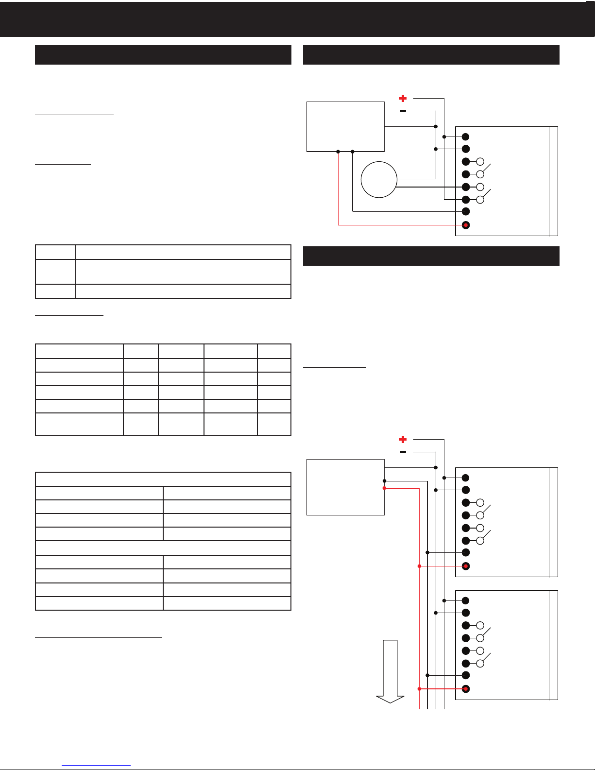
Diagram shows a standard connection between a single TGW,
alarm, and controller or variable frequency drive:
SENVA TG SENSOR
POWER
COMMON
FAN RELAY
ALARM RELAY
OUTPUT 1
OUTPUT 2
ALARM
DDC Analog Inputs
or
Variable Frequency
Drive
DAISY CHAIN OF OUTPUTS
Diagram shows connection between multiple TG sensors wired
in parallel to a controller or variable frequency drive using
analog outputs.
Analog Outputs
The analog outputs (0-5/10V) must be uniform on each TG
sensor in the daisy chain. The 4-20mA output mode is not
compatible with daisy chain wiring.
Output Scaling
Senva recommends using uniform output scaling for each TG
sensor connected to the same daisy chain.
Note: There is no limit to the number of sensors that can be
daisy chained, but wire resistance on long runs should be taken
into account.
SENVA TG SENSOR
POWER
COMMON
FAN RELAY
ALARM RELAY
OUTPUT 1
OUTPUT 2
SENVA TG SENSOR
POWER
COMMON
FAN RELAY
ALARM RELAY
OUTPUT 1
OUTPUT 2
DDC Analog Inputs
or
Variable Frequency
Drive
Additional
TG Sensors
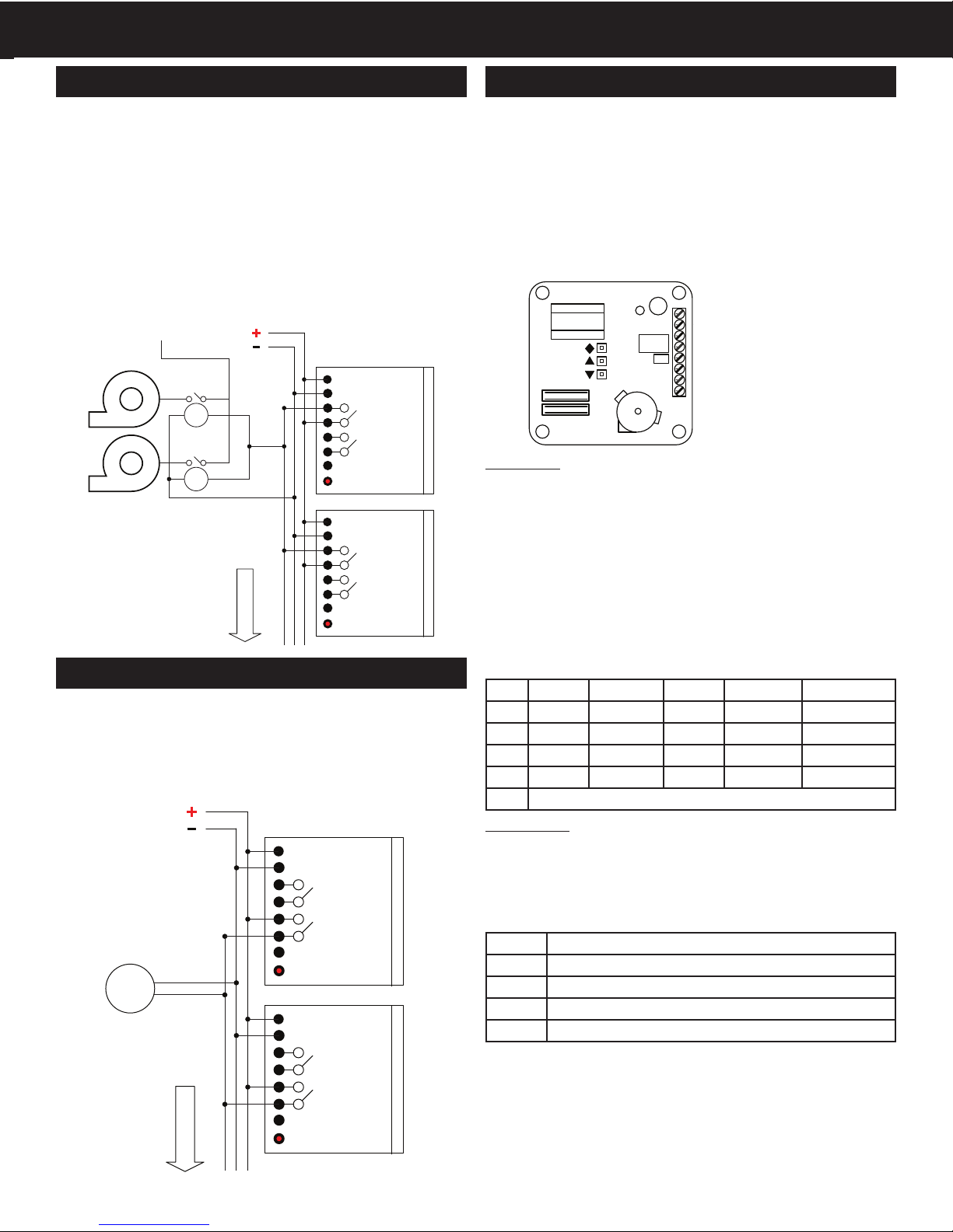
DAISY CHAIN OF FAN RELAYS
Diagram shows connection between one or more devices
wired to an exhaust fan using the fan setpoint relay(s). This
function can be performed by a single TG sensor or a sequence
of multiple TG sensors wired in parallel.
If wiring multiple sensors, ensure that the fan relay setpoints
are uniformly set. The fan relay will activate if any sensor
reaches the warning setpoint.
Device also features a maximum o timer for the fan relay,
to ensure a minimum number of air changes within the
monitored space. See TG Series User’s Guide to enable this
feature.
SENVA TG SENSOR
POWER
COMMON
FAN RELAY
ALARM RELAY
OUTPUT 1
OUTPUT 2
SENVA TG SENSOR
POWER
COMMON
FAN RELAY
ALARM RELAY
OUTPUT 1
OUTPUT 2
Coil
Coil
Main Fan Power
Starter
Relays
Exhaust Fans
Additional
TG Sensors
DAISY CHAIN OF ALARM RELAYS
Diagram shows connection between one or more devices
wired to an alarm using the alarm relay(s) in parallel.
If wiring in a daisy chain, ensure alarm relay setpoints are
uniformly set. The alarm will activate if any sensor reaches the
alarm setpoint.
ALARM
SENVA TG SENSOR
POWER
COMMON
FAN RELAY
ALARM RELAY
OUTPUT 1
OUTPUT 2
SENVA TG SENSOR
POWER
COMMON
FAN RELAY
ALARM RELAY
OUTPUT 1
OUTPUT 2
Additional
TG Sensors
This section will focus only on the following items:
• ‘Quick Start’ options for changing fan/alarm settings
• Altering output type for Outputs 1 and 2.
Setup will timeout and return to normal operation after 60
seconds of no activity, so it is recommended to fully read
through this section before proceeding. (This is an abbreviated
section of the TG Series User’s Guide. Do not attempt to change
any other parameters without utilizing the full TG Series User’s
Guide found online at www.senvainc.com/TGUG)
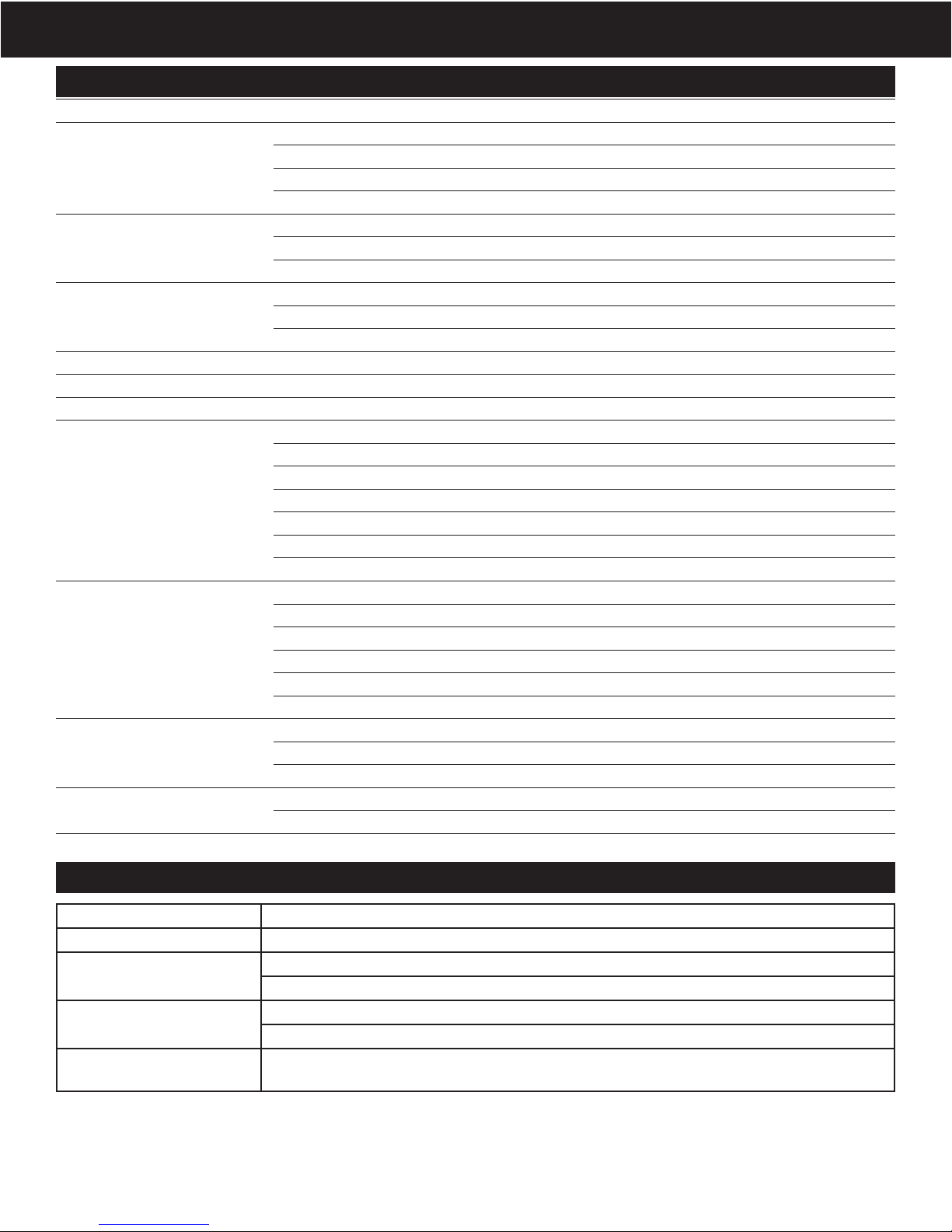
SEL
INC
DEC
POWER
COMMON
FAN IN
FAN OUT
ALARM IN
ALARM OUT
OUTPUT 1
OUTPUT 2
F A
O1
O2
Quick Start
Quick Start allows the user to quickly select from three
precongured parameters for the fan and alarm settings for CO
and NO2. There is also a‘test mode’ for commissioning.
Press the select button uuntil QStARt, scrolls across the LCD.
Press the select button uagain and LCD will read A. This
corresponds to the default fan/alarm settings. From the
table below, choose which quick start parameter best ts
your application using pand q. Press the select button u
to activate the Quick Start conguration and proceed to the
‘Output Type’ section below.
LCD CO Fan CO Alarm NO2 Fan NO2 Alarm Buzzer Delay
A25ppm 100ppm 1ppm 3ppm 30 minutes
815ppm 50ppm 0.7ppm 2ppm 30 minutes
C35ppm 100ppm 1ppm 5ppm 30 minutes
tSt 5ppm 10ppm 0.5ppm 1ppm 2 minutes
ESC Exits back to main User Menu screen
Output Type
After activating Quick Start conguration, the LCD will display
10U (the default 0-10V output scale for Output 1 and Output
2). If required, choose an alternate output scale using pand
q. Press the select button uwith your desired output type
displayed.
LCD Output Type (Output 1 & Output 2)
10U 0-10V Output
1_5 1-5V Output
420 4-20mA Output
0_5 0-5V Output
After selecting the output type, the LCD will return back to the
Quick Start selection. Press qbutton to scroll to ESC and press
the select button u. Display will now show QStArt. Again,
press qbutton to scroll to ESC and press the select button u,
or allow the device to timeout (approximately 60 seconds) to
return to normal operation.
RELAY/OUTPUT SETUP
LCD Menu Buttons
u‘Select’ button
p'Increase/Up' button
q‘Decrease/Down’ button
SPECIFICATIONS
Power supply 15-30VDC/24VAC (1), 4W max, 120mA max.
Analog Outputs
2 programmable outputs 0-10V (default), 0-5V, 1-5V and 4-20mA (menu selectable)
CO output scaling 0-200ppm (default), ranges up to 1000ppm (menu selectable)
NO2 output scaling 0-10ppm (default), ranges up to 20ppm (menu selectable)
Temperature output scaling -20 to 85oC
Fan Relay
Fan relay characteristics N.C. 10A@125VAC, 5A@30VDC
CO fan relay setpoint 25ppm (default), 0-1000ppm (menu selectable)
NO2 fan relay setpoint 1ppm (default), 0-20ppm (menu selectable)
Alarm Relay
Alarm relay characteristics N.C. 1A@30VDC
CO alarm relay setpoint 100ppm (default), 0-1000ppm (menu selectable)
NO2 alarm relay setpoint 3ppm (default), 0-20ppm (menu selectable)
Display 3-1/2 digit LCD Indicates CO ppm, NO2 ppm, Temp (menu selectable)
LED’s Green, Yellow, Red Green = Normal, Yellow = Relay, Red = Alarm
Audible exposure alarm 85dB Piezo transducer 30 minutes above alarm setpoint per UL2034 (menu selectable)
CO Sensor Performance
Type Electrochemical
Accuracy +/-10% of reading @ 20oC
Reproducibility +/-2% of reading
Response time <15 seconds
Certications UL2034 Recognized Component
Long term stability <+/-5% per year
Life expectancy >5 years
NO2 Sensor Performance
Type Electrochemical
Accuracy +/-10% of reading @ 20oC
Reproducibility <+/-3% of reading
Response time <15 seconds
Long term stability <+/-5% per year
Life expectancy >5 years
Operating Environment
Temperature, continuous -20 to 40oC
Temperature, intermittent -30 to 55oC
Humidity 15-95% continuous, 0-95% intermittent
Enclosure Material ABS/Polycarbonate
Dimensions 4.0”h x 4.4”w x 2.1”d
(1) One side of transformer secondary is connected to signal common. Dedicated transformer is recommended.
Symptom Solution
No output Check wiring. Ensure power supply meets requirements.
CO reading error Verify control panel software is congured for correct output scaling.
Sensor contaminated or at end of 5-year life. Replace sensor.
NO2 reading error Verify control panel software is congured for correct output scaling.
Sensor contaminated or at end of 5-year life. Replace sensor.
Relay Function Verify setpoint. Verify test gas concentration. Cover sensor to prevent drafts and dilution during
test.
TROUBLESHOOTING
Revised 9/6/2017 Document # 152-0270-0D
Other manuals for TG Series
6
This manual suits for next models
1
Table of contents
Other senva Accessories manuals

senva
senva TotalSense Series User manual

senva
senva TG Series User manual

senva
senva TG Series Installation and operating instructions

senva
senva AQ Series User manual

senva
senva TG Series User manual

senva
senva TG Series User manual

senva
senva TotalSense Series User manual

senva
senva TG Series User manual

senva
senva TG Series User manual

senva
senva TotalSense Series User manual


