9. Assemble the speaker baffles using liquid
plastic cement to secure components. Use one
enclosure ring for the front speaker and two
for the rear speaker. Wire the speakers in series
as described in Step 10 prior to placing the
speakers in the baffles.
10. Wire the speakers in series as follows. First,
trim 6.5”from the left purple speaker wire and
thread one end of the trimmed piece through
the backside of each speaker baffle end plate.
Next, thread the wires that remain attached to
the speaker harness through the backsides of
the baffle end plates: thread the short segment
through the end plate for the front speaker
and the untrimmed segment through the end
plate for the rear speaker. Solder one end of
the trimmed 6.5”wire segment to the inner
terminal of each speaker. Finally, solder the
short harness wire to the outer terminal of
the front speaker and the untrimmed harness
wire to the outer terminal of the rear speaker.
(Figure 1)
11. Finish the speaker assemblies by pressing
the speakers up into the baffles and securing
the mounting flanges in place. Place the
finished speaker assemblies face down in
the predetermined mounting locations. If
the speaker fit seems loose, affix a gasket or
small amount of double-sided foam tape to
the edges of the mounting flanges and press
securely into place; ensure that no adhesive
is applied to or covers any part of the speaker
diaphragm.
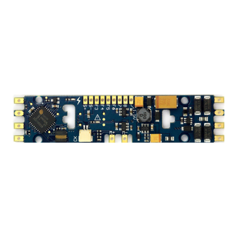
12. Attach the TSU-KT1000 P42 decoder to the
locomotive using the screws removed from the
factory light board in Step 2. (Photo 13)
13. Plug each wire harness into the appropriate
2-pin connector. The motor harness connectors
are located in the middle of the decoder and
labeled F (front) and R (rear) for reference. The
speaker harness connector is located at the
front of the decoder and labeled SPKR.
(Photo 14)
14. Your installation is now complete! Place the
model on the mainline, select Address 3 and
test to ensure proper operation.
15. Tuck any loose wires into the space between
the decoder and the frame and replace the
shell, making sure to line the light pipes up with
the LEDs on the board.
Figure 1
Photo 13
Photo 14


