Digital Control FALCON F5 SUB-K REBAR User manual

FALCON F
SUB-K REBAR USER MANUAL
DCI DigiGuide 07.08.2022
DIGITAL CONTROL, INC
19625
nd Ave S Suite B
Kent, WA 98032 U.S.
dci@digital-control.com | digital - control.com
1.800.288.3610 | 1.425.251.0559
FALCON F
SUB-K REBAR
DCI DigiGuide User Manual
07.08.2022
Important Safety Info
Bootcamp
Initial Setup
Jobsite Setup
During Drilling
Post Drilling
Advanced Topics

FALCON F
SUB-K REBAR USER MANUAL
DCI DigiGuide 07.08.2022
DIGITAL CONTROL, INC 2
Important Safety Info
GENERAL SAFETY WARNING
Only operate your DCI guidance system in accordance with the
operating instructions for your system.
Serious injury and death, as well as property damage, can result if
underground drilling equipment strikes a natural gas line, high-voltage
electrical cable, or other utility.
Work slowdowns and cost overruns can occur if you do not use your
system correctly.
You must properly calibrate your DCI guidance system in connection
with each drilling project. If you fail to do so, depth readings will likely be
inaccurate.
Interference can lead to inaccurate depth readings and/or interruption
of data. See "Special Notes About Interference" for more details.
DCI guidance systems are used to locate and guide the transmitter
(housing) underground. They cannot be used to locate underground
utilities.
Failure to
fi
nd the front and rear locate points can lead to inaccuracies
which may result in drilling o
ff
-path and striking an underground utility.
The locate line on a DCI locator does not indicate the position of the drill
head. DCI locators track the transmitter in its housing, which sits behind
the drill bit. Also, when drilling steep and/or deep, the locate line may
indicate a position behind or ahead of the transmitter. Please see "Steep
and Deep" under Advanced Topics for important information about
accurately locating the drill head when drilling steep and/or deep.
FALCON F
SUB-K REBAR USER MANUAL
DCI DigiGuide 07.08.2022
DIGITAL CONTROL, INC 3
Ensure that all underground utilities have been located, exposed, and/or
accurately marked prior to drilling. Follow all proper safety precautions,
such as potholing.
DCI equipment is not explosion-proof and should never be used near
fl
ammable or explosive substances.
Wear jobsite protective/safety clothing such as dielectric boots, gloves,
hard hat, high-visibility vest, and safety glasses.
Maintain a minimum distance of 8 inches (20 cm) from the front of the
locator to the user
’
s torso to ensure compliance with RF exposure
requirements.
Comply with federal, state, and local governmental regulations (such as
OSHA) and all other customary or required safety precautions.
If you have any questions about the operation of your guidance system,
please contact DCI Customer Service for assistance.
SPECIAL NOTES ABOUT INTERFERENCE
While DCI guidance systems provide you with technology to combat active
interference (and passive interference, with the Sub-K Rebar transmitter),
no guidance system is immune to all interference.
Interference can lead to inaccurate depth readings and/or interruption or
loss of data. Never rely on data that does not display quickly and/or remain
stable.
The Falcon frequency optimizer selects frequencies based on measured
interference at a speci
fi
c time and location.
Interference levels change with time and with even minor changes in
location. The frequency optimizer is not a substitute for prudent operator
judgment. If performance drops while drilling, consider switching to the
other selected band (not available on the Falcon F
) or use Max Mode.

FALCON F
SUB-K REBAR USER MANUAL
DCI DigiGuide 07.08.2022
DIGITAL CONTROL, INC 4
An
A
on the screen can indicate signal Attenuation due to the presence of
excessive interference, which can make depth readings inaccurate.
Attenuation is normal in shallow depths less than 8 ft (2.4 m). If the signal
strength is also
fl
ashing; this indicates extreme interference. Depth and
locate points may be compromised and the locator will not calibrate.
Interference is classi
fi
ed as either active (generating electro-magnetic
signals) or passive (material that can conduct or block electro-magnetic
signals). Sources of interference may include:
Active
Tra
ffi
c signal loops
Buried dog fences
Cathodic protection
Radio communications
Security systems
Microwave towers
Power, phone,
fi
ber-trace and cable TV lines
Passive
Metal pipes
Rebar
Trench plates
Chain-link fences
Vehicles
Saltwater/salt domes
Conductive earth, such as iron ore

FALCON F
SUB-K REBAR USER MANUAL
DCI DigiGuide 07.08.2022
DIGITAL CONTROL, INC 5
If you have any questions about the operation of your guidance system,
please contact DCI Customer Service for assistance.
ENVIRONMENTAL REQUIREMENTS
System working altitude: up to 6562 ft (
m).
Storage and transportation temperature: -40° to
°F (-40° to
°C).
Operation may be compromised if the equipment is subjected to conditions
outside these speci
fi
ed limits.
Ship in original carrying case or packaging of su
ffi
cient durability to prevent
mechanical shock to equipment during transportation.
If you have any questions about the operation of your guidance system,
please contact DCI Customer Service for assistance.
STORAGE AND SHIPPING OF BATTERIES
Remove the batteries from all system components during shipping and
prolonged storage. Failure to do so may result in battery leakage, which may
lead to risk of explosion, health risks, and/or damage.
Store and transport batteries using a suitable protective case that will keep
batteries safely isolated from one another. Failure to do so may result in
short circuits, which may lead to hazardous conditions including
fi
re.
Lithium-ion batteries must be packaged and shipped by trained and
certi
fi
ed personnel only. Never ship damaged batteries.
If you have any questions about the operation of your guidance system,
please contact DCI Customer Service for assistance.
FALCON F
SUB-K REBAR USER MANUAL
DCI DigiGuide 07.08.2022
DIGITAL CONTROL, INC 6
Bootcamp
HDD LOCATING HISTORY
Locating in the horizontal directional drilling (HDD) industry was initially
based on locating a buried cable by sweeping the locator back and forth to
fi
nd the highest signal strength (peak signal), indicating that the locator was
over the cable. Unfortunately, this method did not always guarantee an
accurate location of the cable, nor did it provide any depth information.
This
“
peak signal
”
method was adapted to HDD with the introduction of a
transmitter that provides information on the position and depth of the drill
head. However, this method is unreliable and inaccurate because the peak
signal strength is not always directly above the transmitter housing.
In addition, peak signal locating doesn
’
t show where the drill tool is headed.
Think of drilling like driving a car: it is more e
ff
ective to look ahead through
the windshield to see where you are going than to look down at the road
through the
fl
oorboard to keep the car (drill tool) on the road (drill path).
BALL-IN-THE-BOX GUIDANCE
DCI
’
s design uses a
“
locate point
”
in the transmitter signal. The Front Locate
Point (FLP), which is out ahead of the transmitter, shows where the
transmitter housing
is heading.
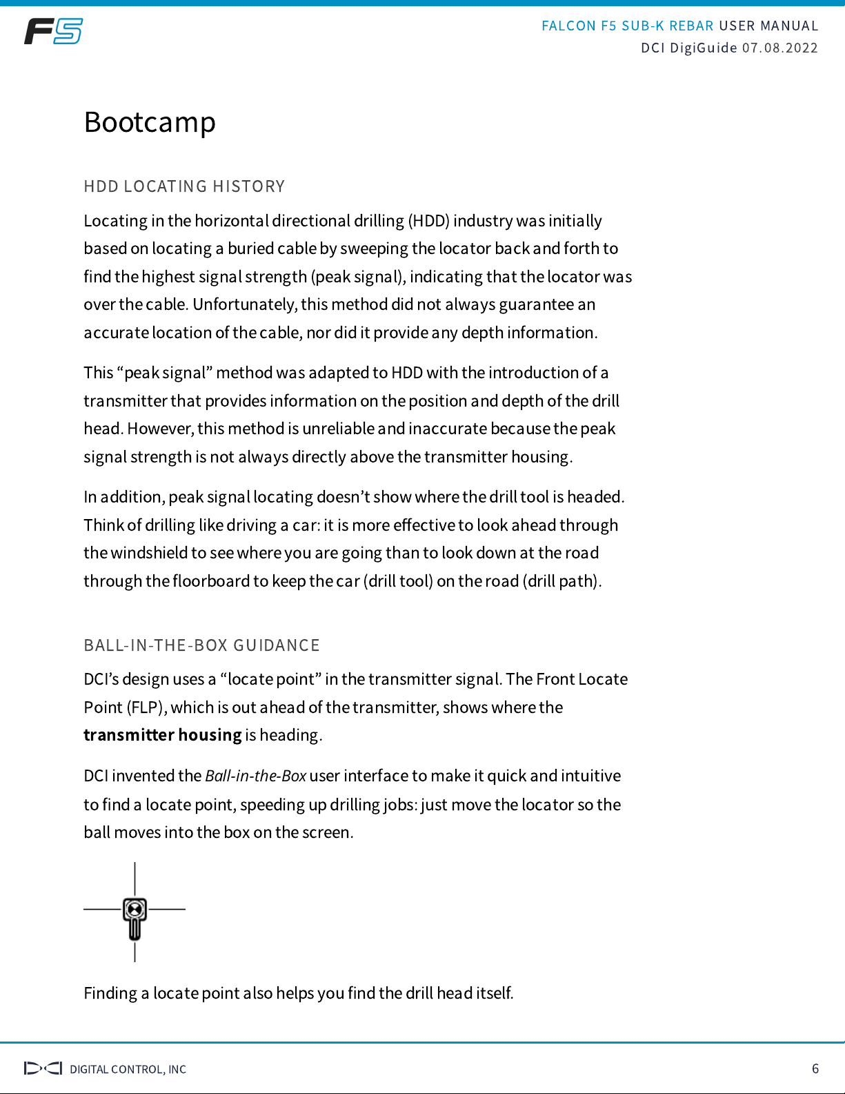
DCI invented the
Ball-in-the-Box
user interface to make it quick and intuitive
to
fi
nd a locate point, speeding up drilling jobs: just move the locator so the
ball moves into the box on the screen.
Finding a locate point also helps you
fi
nd the drill head itself.
FALCON F
SUB-K REBAR USER MANUAL
DCI DigiGuide 07.08.2022
DIGITAL CONTROL, INC 7
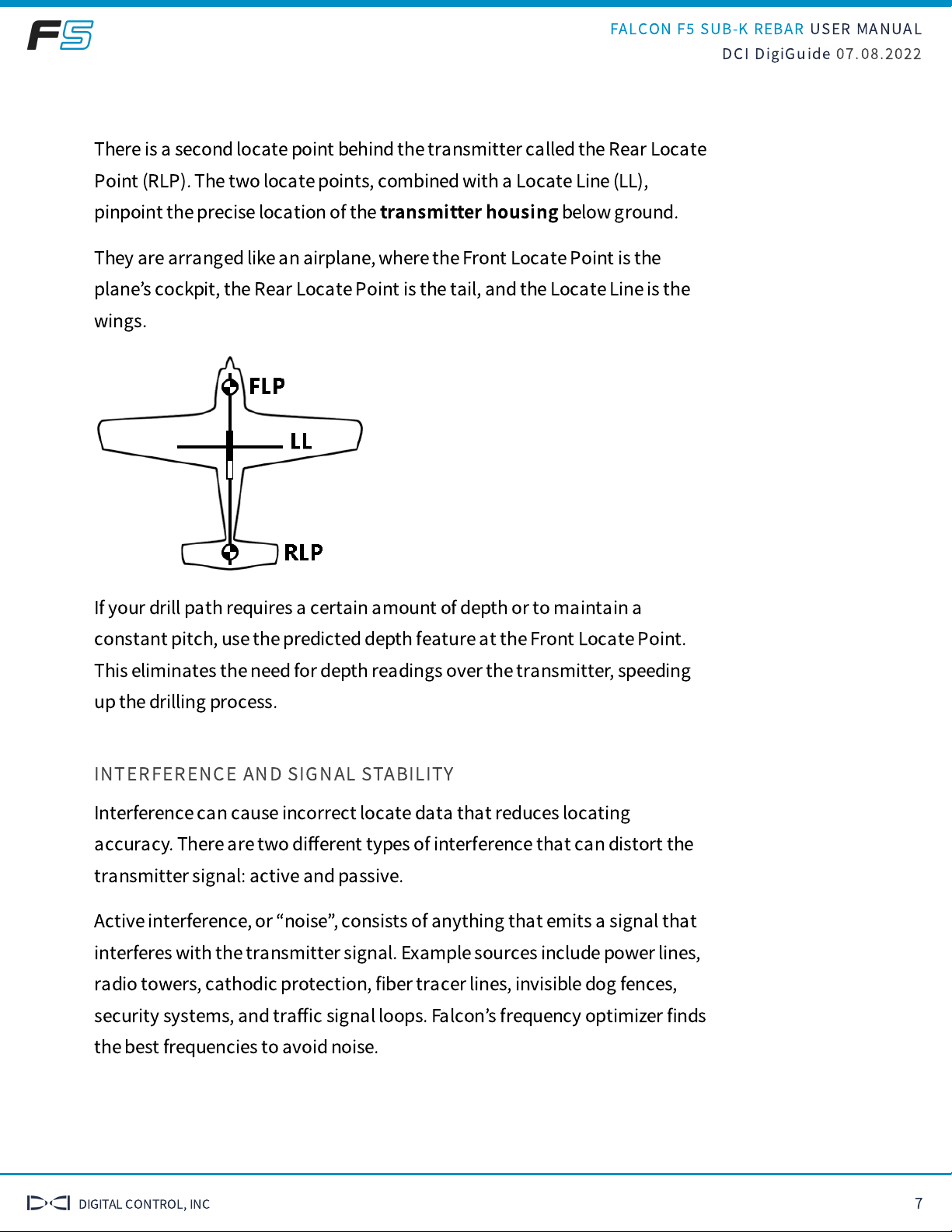
There is a second locate point behind the transmitter called the Rear Locate
Point (RLP). The two locate points, combined with a Locate Line (LL),
pinpoint the precise location of the
transmitter housing
below ground.
They are arranged like an airplane, where the Front Locate Point is the
plane
’
s cockpit, the Rear Locate Point is the tail, and the Locate Line is the
wings.
If your drill path requires a certain amount of depth or to maintain a
constant pitch, use the predicted depth feature at the Front Locate Point.
This eliminates the need for depth readings over the transmitter, speeding
up the drilling process.
INTERFERENCE AND SIGNAL STABILITY
Interference can cause incorrect locate data that reduces locating
accuracy. There are two di
ff
erent types of interference that can distort the
transmitter signal: active and passive.
Active interference, or
“
noise
”
, consists of anything that emits a signal that
interferes with the transmitter signal. Example sources include power lines,
radio towers, cathodic protection,
fi
ber tracer lines, invisible dog fences,
security systems, and tra
ffi
c signal loops. Falcon
’
s frequency optimizer
fi
nds
the best frequencies to avoid noise.
FALCON F
SUB-K REBAR USER MANUAL
DCI DigiGuide 07.08.2022
DIGITAL CONTROL, INC 8
Passive interference consists of anything that blocks or distorts the
transmitter signal resulting in incorrect depths or missing data. Example
sources include rebar, guard rails, bridge abutments, chain link fencing,
salt/saltwater and soil high in metal ore. The Falcon sub-kHz transmitter
(available for Falcon F
and F
+ only) helps cut through passive interference
without distorting the signal.
An A on the screen can indicate signal Attenuation due to the presence of
excessive interference, which can make depth readings inaccurate.
Attenuation is normal in shallow depths less than 8 feet (2.4 m). If the signal
strength is also
fl
ashing, this indicates extreme interference. Depth and
locate points may be compromised and the locator will not calibrate.
OPTIMIZE EVERY JOB
Noise varies by amount and frequency depending on where you are and
even the time of day. That
’
s why it
’
s important to
fi
nd the best frequencies
for
every bore
.
This is called
frequency optimization
, and only Falcon has it. Using
frequencies with the highest probability of success against noise increases
locating accuracy and reduces the risk of tripping out.
Falcon
’
s frequency optimizer scans through
hundreds
of frequencies, then
bundles those with the lowest noise into
fi
nely-tuned bands that work best
for the current job.
Select two bands and switch between them mid-bore if needed (not
available on the Falcon F
with singleband).
The Falcon locators with
Quick Scan Pair
o
ff
er features to make the selection
of bands faster and easier. Two clicks select the two preset bands selected
for your region.

FALCON F
SUB-K REBAR USER MANUAL
DCI DigiGuide 07.08.2022
DIGITAL CONTROL, INC 9
MENU NAVIGATION
The Falcon F
/F
/F
+/F
+ has a toggle switch on top and a trigger switch
under the handle to navigate the menu system and select options.
Use the
-way toggle switch to access a menu, move between menu options,
and open shortcuts.
Shortcuts require you to hold the toggle for a second or longer; we call this a
“
hold toggle
”
. For example, from the Locate Mode screen, open a transmitter
band selection shortcut by holding the toggle right.
Use the trigger switch to power on the locator, select a menu option, and to
take a depth reading.
Pull and release (click) the trigger to select. In some cases, you
’
ll need to
hold the trigger for a second or more to use a function, such as turning the
locator on or taking a depth reading.
BENEFITS OF DATALOGGING
Utilities increasingly require a digital as-built report to ensure drilling
parameters were met.
The DataLog® feature on your locator lets you easily capture and store the
rod-by-rod data of your pilot bore.
When used with DCI
’
s LWD Mobile app, geo-tagging the entry and exit
automatically ties the as-built to a physical location.
FALCON F
SUB-K REBAR USER MANUAL
DCI DigiGuide 07.08.2022
DIGITAL CONTROL, INC 10
With a DigiTrak DataLog Management (DDM) subscription, use your mobile
device to upload DataLogs to your cloud account even during drilling to
show progress to back-o
ffi
ce personnel.
After importing your DataLog job into our Log-While-Drilling (LWD) 3.0
software, you can edit, annotate, and
fi
nalize the precise report you or your
customer requires.
On the DigiTrak Aurora remote display, use our free LWD Live app to view the
drill pro
fi
le in real-time as each rod is completed.
SCREEN ELEMENTS OVERVIEW
The Locate Mode, Depth, and Predicted Depth screens are the primary
screens you will use for locating.
When the locator is detecting a signal from a transmitter, the Locate Mode
screen provides real-time data about the transmitter
’
s location,
temperature, pitch, roll, and signal strength.
Depth data appears when the trigger is held at the Locate Line (LL) and
predicted depth appears when held at the Front Locate Point.
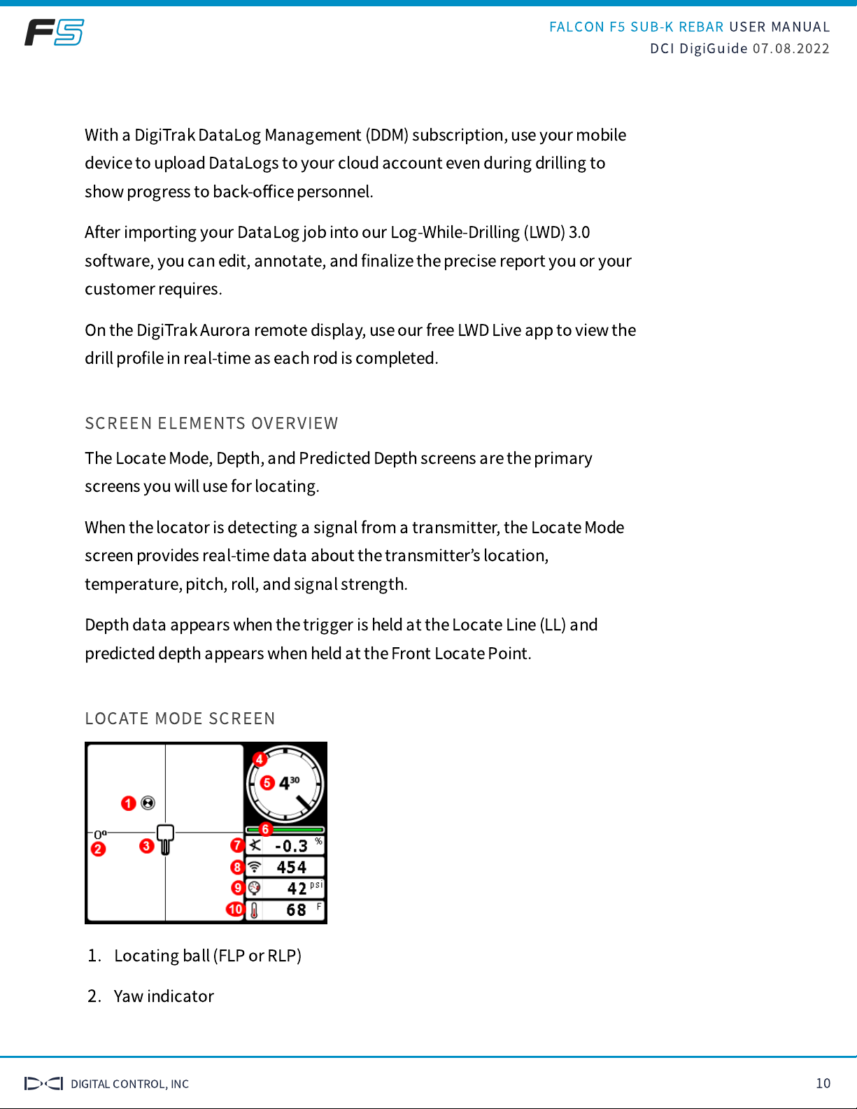
LOCATE MODE SCREEN
1. Locating ball (FLP or RLP)
2. Yaw indicator
FALCON F
SUB-K REBAR USER MANUAL
DCI DigiGuide 07.08.2022
DIGITAL CONTROL, INC 11
3. Locator
4. Roll indicator
5. Roll value
6. Roll/pitch update meter
7. Transmitter pitch
8. Power Mode and Transmitter signal strength
9. Transmitter
fl
uid pressure
10. Transmitter temperature
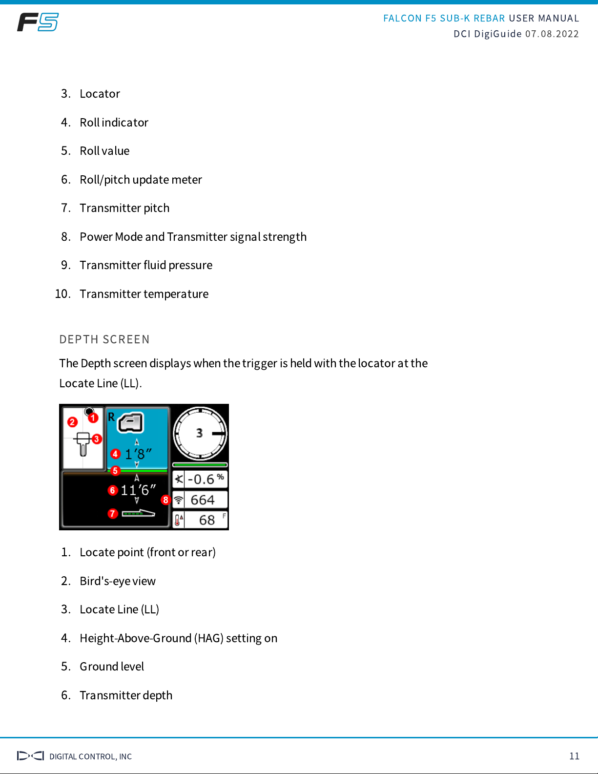
DEPTH SCREEN
The Depth screen displays when the trigger is held with the locator at the
Locate Line (LL).
1. Locate point (front or rear)
2. Bird's-eye view
3. Locate Line (LL)
4. Height-Above-Ground (HAG) setting on
5. Ground level
6. Transmitter depth
FALCON F
SUB-K REBAR USER MANUAL
DCI DigiGuide 07.08.2022
DIGITAL CONTROL, INC 12
7. Transmitter battery strength
8. Transmitter power level
When the HAG setting is disabled, the locator displays at
ground level and must be placed on the ground during depth
readings.
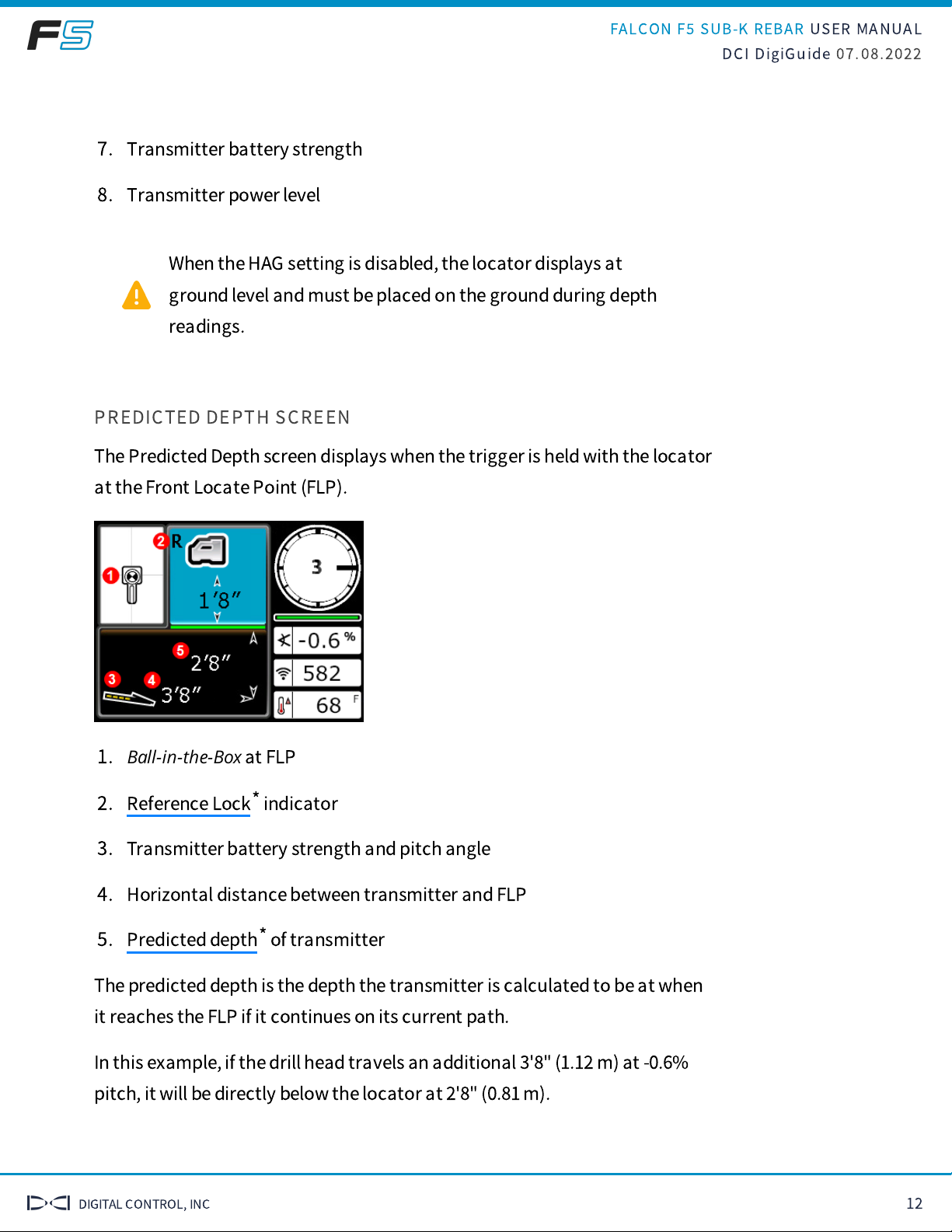
PREDICTED DEPTH SCREEN
The Predicted Depth screen displays when the trigger is held with the locator
at the Front Locate Point (FLP).
1.
Ball-in-the-Box
at FLP
2. indicator
3. Transmitter battery strength and pitch angle
4. Horizontal distance between transmitter and FLP
5. of transmitter
The predicted depth is the depth the transmitter is calculated to be at when
it reaches the FLP if it continues on its current path.
In this example, if the drill head travels an additional 3'8" (1.12 m) at -0.6%
pitch, it will be directly below the locator at 2'8" (0.81 m).
Reference Lock*
Predicted depth*
FALCON F
SUB-K REBAR USER MANUAL
DCI DigiGuide 07.08.2022
DIGITAL CONTROL, INC 13
Do not take a predicted depth reading when the locator is over
the Rear Locate Point (RLP).
GLOSSARY DEFINITIONS
*REFERENCE LOCK INDICATOR
Indicates a reference signal has been obtained for displaying the locate line.
Displays at the top of the Locate Mode screen.
*PREDICTED DEPTH
The Predicted Depth screen displays when the trigger is held with the locator at the
Front Locate Point (FLP). The predicted depth is how deep the transmitter is
calculated to be when it reaches the front locate point if it continues on its current
path.
FALCON F
SUB-K REBAR USER MANUAL
DCI DigiGuide 07.08.2022
DIGITAL CONTROL, INC 14
Initial Setup
REGISTERING YOUR EQUIPMENT
STEP 1 OF 2
Stu
ff
You Should Know
Registering your equipment activates the product warranty.
Registering also allows us to contact you if it is recovered after being lost or
stolen.
If you want to enable the Lock Out Capability (LOC) feature, contact DCI
support.
See the DCI website for warranty terms and conditions.
STEP 2 OF 2
Contact your authorized DCI dealer or DCI to register your equipment.
You will need the equipment serial number and your company contact
information.
Here
’
s where to
fi
nd your serial number:
Locator: in the battery compartment
Transmitter: engraved on the steel body
Remote display: decal on the back
POWER ON

FALCON F
SUB-K REBAR USER MANUAL
DCI DigiGuide 07.08.2022
DIGITAL CONTROL, INC 15
STEP 1 OF 5
Check the charge level of your battery; each of the
fi
ve lights on a li-ion
battery represents about 20% capacity.
NiMH batteries do not have a power meter. You can view
battery life in the top banner of the Main menu.
STEP 2 OF 5
Insert battery in the locator.
FALCON F
SUB-K REBAR USER MANUAL
DCI DigiGuide 07.08.2022
DIGITAL CONTROL, INC 16
STEP 3 OF 5
Pull the trigger to turn on the locator.
STEP 4 OF 5
Click to con
fi
rm you
’
ve read the manual.
STEP 5 OF 5
Click again to continue.
TRANSMITTER SETUP
STEP 1 OF 3
Your transmitter comes
with two battery contact
springs and one battery cap
tool.
STEP 2 OF 3
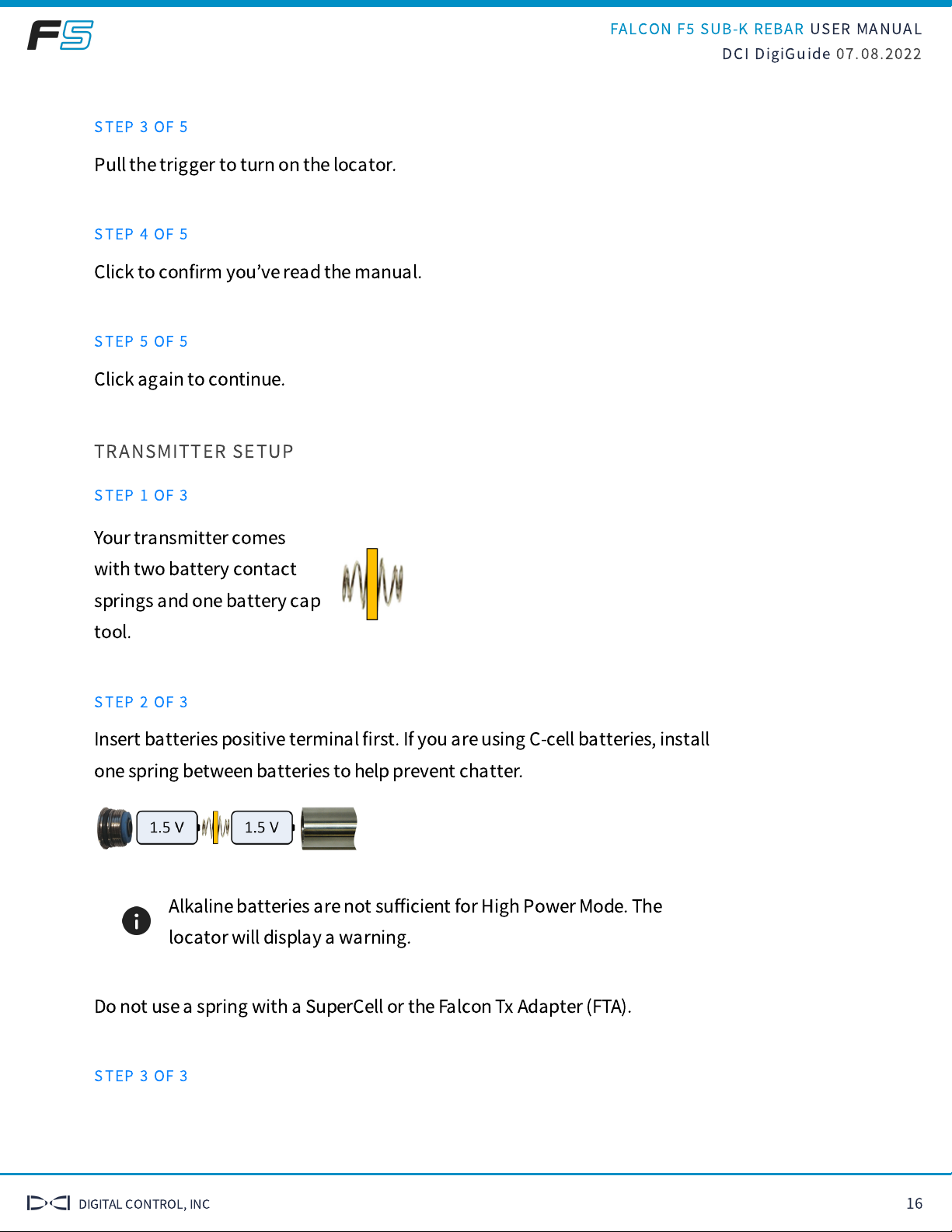
Insert batteries positive terminal
fi
rst. If you are using C-cell batteries, install
one spring between batteries to help prevent chatter.
Alkaline batteries are not su
ffi
cient for High Power Mode. The
locator will display a warning.
Do not use a spring with a SuperCell or the Falcon Tx Adapter (FTA).
STEP 3 OF 3
FALCON F
SUB-K REBAR USER MANUAL
DCI DigiGuide 07.08.2022
DIGITAL CONTROL, INC 17
SET HEIGHT-ABOVE-GROUND
STEP 1 OF 6
Stuff You Should Know
Use Height-Above-Ground (HAG) to set a height measurement on the locator
so you don
’
t have to put it on the ground for a depth reading.
Raising the locator above the ground also provides separation from
underground interference that might otherwise reduce the transmitter
’
s
range or cause variable readings.
STEP 2 OF 6
Hold the locator at your side as if you were holding a suitcase.
STEP 3 OF 6
Measure the distance between the ground and the bottom of the locator
using a tape measure.
STEP 4 OF 6
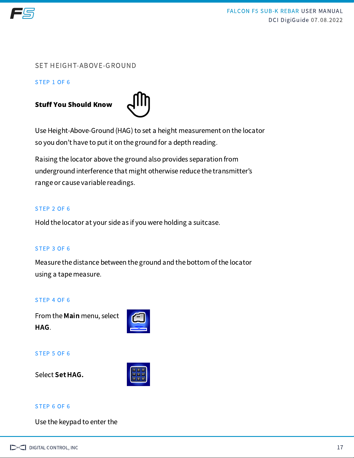
From the
Main
menu, select
HAG
.
STEP 5 OF 6
Select
Set HAG.
STEP 6 OF 6
Use the keypad to enter the
FALCON F
SUB-K REBAR USER MANUAL
DCI DigiGuide 07.08.2022
DIGITAL CONTROL, INC 18
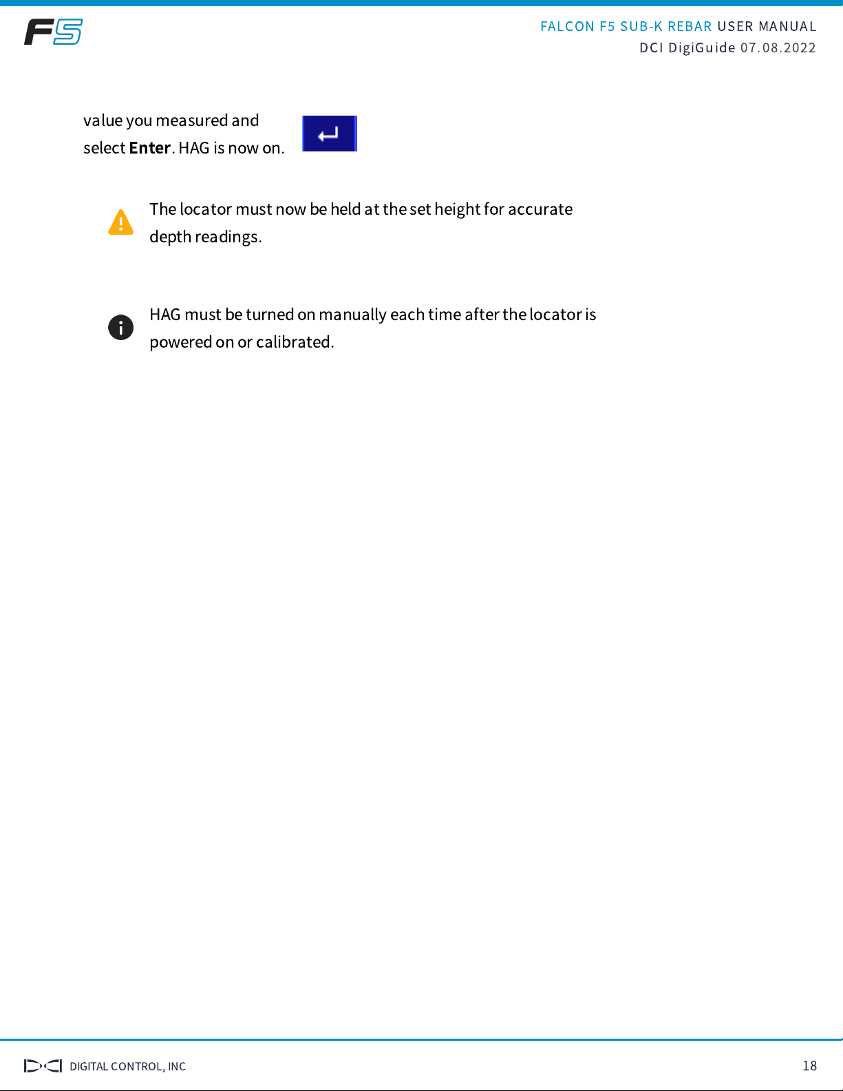
value you measured and
select
Enter
. HAG is now on.
The locator must now be held at the set height for accurate
depth readings.
HAG must be turned on manually each time after the locator is
powered on or calibrated.

FALCON F
SUB-K REBAR USER MANUAL
DCI DigiGuide 07.08.2022
DIGITAL CONTROL, INC 19
Jobsite Setup
POWER ON
STEP 1 OF 5
Check the charge level of your battery; each of the
fi
ve lights on a li-ion
battery represents about 20% capacity.
NiMH batteries do not have a power meter. You can view
battery life in the top banner of the Main menu.
STEP 2 OF 5
Insert battery in the locator.

FALCON F
SUB-K REBAR USER MANUAL
DCI DigiGuide 07.08.2022
DIGITAL CONTROL, INC 20
STEP 3 OF 5
Pull the trigger to turn on the locator.
STEP 4 OF 5
Click to con
fi
rm you
’
ve read the manual.
STEP 5 OF 5
Click again to continue.
SELECT/CHANGE TX TYPE
STEP 1 OF 4
Stu
ff
You Should Know
Your locating system can use di
ff
erent transmitters: FT
, FT
, or FTR.
The transmitter selected on your locator must match the transmitter in use.
Transmitter:
Other Digital Control Industrial Equipment manuals


Popular Industrial Equipment manuals by other brands


A to Z Rubber Stamps
A to Z Rubber Stamps RAPIDPRINT A Series manual

Panasonic
Panasonic EXC14CG quick start guide

Husky
Husky 31318 Assembly, Installation, Operation and Maintenance Instructions

Emerson
Emerson Liebert eXL installation manual

Orion
Orion L77-20 manual

Schmalz
Schmalz EVE-TR 4 - 8 DC operating instructions