Digital Control Aurora User manual
AURORA USER MANUAL
DCI DigiGuide 07.08.2022
DIGITAL CONTROL, INC
19625
nd Ave S Suite B
Kent, WA 98032 U.S.
dci@digital-control.com | digital - control.com
1.800.288.3610 | 1.425.251.0559
AURORA
DCI DigiGuide User Manual
07.08.2022
Important Safety Info
Bootcamp
Initial Setup
Jobsite Setup
During Drilling
Post Drilling
Advanced Topics
AURORA USER MANUAL
DCI DigiGuide 07.08.2022
DIGITAL CONTROL, INC 2
Important Safety Info
GENERAL SAFETY WARNINGS
Only operate your DCI guidance system in accordance with the
operating instructions for your system.
Serious injury and death, as well as property damage, can result if
underground drilling equipment strikes a natural gas line, high-voltage
electrical cable, or other utility.
Work slowdowns and cost overruns can occur if you do not use your
system correctly.
You must properly calibrate your DCI guidance system in connection
with each drilling project. If you fail to do so, depth readings will likely be
inaccurate.
Interference can lead to inaccurate depth readings and/or interruption
of data. See "Special Notes About Interference" for more details.
DCI guidance systems are used to locate and guide the transmitter
(housing) underground. They cannot be used to locate underground
utilities.
Failure to
fi
nd the front and rear locate points can lead to inaccuracies
which may result in drilling o
ff
-path and striking an underground utility.
The locate line on a DCI locator does not indicate the position of the drill
head. DCI locators track the transmitter in its housing, which sits behind
the drill bit. Also, when drilling steep and/or deep, the locate line may
indicate a position behind or ahead of the transmitter. Please see "Steep
and Deep" under Advanced Topics
for important information about
accurately locating the drill head when drilling steep and/or deep.
AURORA USER MANUAL
DCI DigiGuide 07.08.2022
DIGITAL CONTROL, INC 3
Ensure that all underground utilities have been located, exposed, and/or
accurately marked prior to drilling. Follow all proper safety precautions,
such as potholing.
DCI equipment is not explosion-proof and should never be used near
fl
ammable or explosive substances.
Wear jobsite protective/safety clothing such as dielectric boots, gloves,
hard hat, high-visibility vest, and safety glasses.
Maintain a minimum distance of 20 cm from the front of the locator to
the user
’
s torso to ensure compliance with RF exposure requirements.
Comply with federal, state, and local governmental regulations (such as
OSHA) and all other customary or required safety precautions.
If you have any questions about the operation of your guidance system,
please contact DCI Customer Service for assistance.
SPECIAL NOTES ABOUT INTERFERENCE
While DCI guidance systems provide you with technology to combat active
interference (and passive interference, with the Sub-K Rebar transmitter),
no guidance system is immune to all interference.
Interference can lead to inaccurate depth readings and/or interruption or
loss of data. Never rely on data that does not display quickly and/or remain
stable.
The Falcon frequency optimizer selects frequencies based on measured
interference at a speci
fi
c time and location.
Interference levels change with time and with even minor changes in
location. The frequency optimizer is not a substitute for prudent operator
judgment. If performance drops while drilling, consider switching to the
other selected band (not available on the Falcon F
) or use Max Mode.
AURORA USER MANUAL
DCI DigiGuide 07.08.2022
DIGITAL CONTROL, INC 4
An
A
on the screen can indicate signal Attenuation due to the presence of
excessive interference, which can make depth readings inaccurate.
Attenuation is normal in shallow depths less than 2.4 m. If the signal
strength is also
fl
ashing; this indicates extreme interference. Depth and
locate points may be compromised and the locator will not calibrate.
Interference is classi
fi
ed as either active (generating electro-magnetic
signals) or passive (material that can conduct or block electro-magnetic
signals). Sources of interference may include:
Active
Tra
ffi
c signal loops
Buried dog fences
Cathodic protection
Radio communications
Security systems
Microwave towers
Power, phone,
fi
ber-trace and cable TV lines
Passive
Metal pipes
Rebar
Trench plates
Chain-link fences
Vehicles
Saltwater/salt domes
Conductive earth, such as iron ore

AURORA USER MANUAL
DCI DigiGuide 07.08.2022
DIGITAL CONTROL, INC 5
If you have any questions about the operation of your guidance system,
please contact DCI Customer Service for assistance.
ENVIRONMENTAL REQUIREMENTS
System working altitude: up to
m.
Storage and transportation temperature: -40° to
°C.
Operation may be compromised if the equipment is subjected to conditions
outside these speci
fi
ed limits.
Ship in original carrying case or packaging of su
ffi
cient durability to prevent
mechanical shock to equipment during transportation.
If you have any questions about the operation of your guidance system,
please contact DCI Customer Service for assistance.
STORAGE AND SHIPPING OF BATTERIES
Remove the batteries from all system components during shipping and
prolonged storage. Failure to do so may result in battery leakage, which may
lead to risk of explosion, health risks, and/or damage.
Store and transport batteries using a suitable protective case that will keep
batteries safely isolated from one another. Failure to do so may result in
short circuits, which may lead to hazardous conditions including
fi
re.
Lithium-ion batteries must be packaged and shipped by trained and
certi
fi
ed personnel only. Never ship damaged batteries.
If you have any questions about the operation of your guidance system,
please contact DCI Customer Service for assistance.
AURORA USER MANUAL
DCI DigiGuide 07.08.2022
DIGITAL CONTROL, INC 6
Bootcamp
MENU NAVIGATION
When powered on, the Aurora automatically displays its
Home
screen.
The Aurora has a touchscreen to navigate the menu system and select
options. Use the soft pad of your
fi
ngertip to tap the display or use gloves
with a touchscreen-compatible
fi
ngertip. Never use a
fi
ngernail or foreign
object.
The Aurora touchscreen
features a taskbar at the
bottom. The taskbar shows
any open applications as
well as an icon for the
Main
menu.
The Aurora also has shortcuts directly to key features. For example, to
change the telemetry channel or locator type, hold your
fi
nger on the
telemetry channel label at the top of the screen. Aurora opens the
appropriate
Settings
window in the
Main
menu.
To return to the Home
screen, tap
Home
in the
taskbar.

AURORA USER MANUAL
DCI DigiGuide 07.08.2022
DIGITAL CONTROL, INC 7
Initial Setup
REGISTERING YOUR EQUIPMENT
STEP 1 OF 2
Stu
ff
You Should Know
Registering your equipment activates the product warranty.
Registering also allows us to contact you if it is recovered after being lost or
stolen.
If you want to enable the Lock Out Capability (LOC) feature, contact DCI
support.
See the DCI website for warranty terms and conditions.
STEP 2 OF 2
Contact your authorized DCI dealer or DCI to register your equipment.
You will need the equipment serial number and your company contact
information.
Here
’
s where to
fi
nd your serial number:
Locator: in the battery compartment
Transmitter: engraved on the steel body
Remote display: decal on the back
POWER ON
AURORA USER MANUAL
DCI DigiGuide 07.08.2022
DIGITAL CONTROL, INC 8
STEP 1 OF 2
Connect Aurora to the drill rig power source.
STEP 2 OF 2
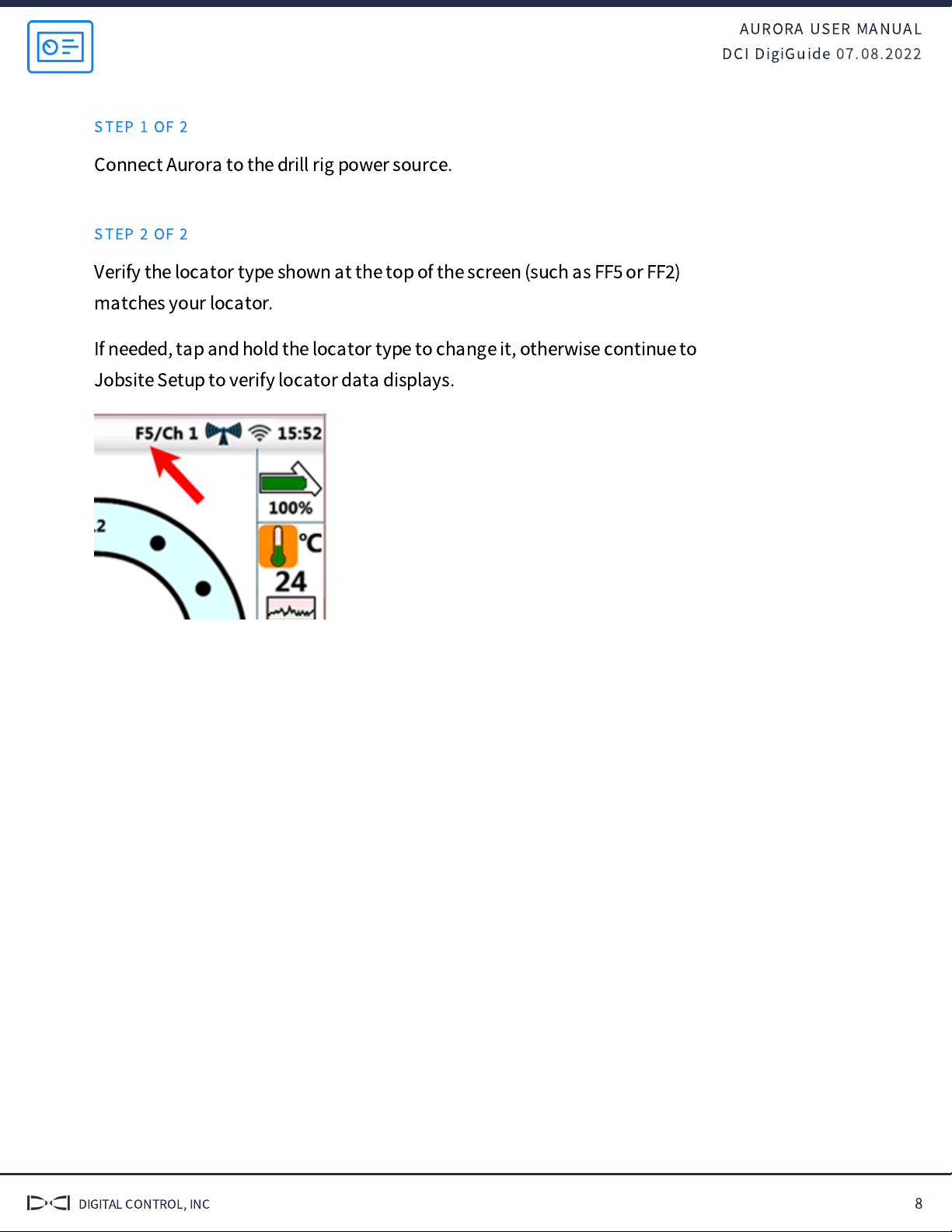
Verify the locator type shown at the top of the screen (such as FF
or FF
)
matches your locator.
If needed, tap and hold the locator type to change it, otherwise continue to
Jobsite Setup to verify locator data displays.

AURORA USER MANUAL
DCI DigiGuide 07.08.2022
DIGITAL CONTROL, INC 9
Jobsite Setup
INSTALL ANTENNA
STEP 1 OF 3
Ensure antenna and display connectors are free of debris and that the
antenna pin is straight and intact.
STEP 2 OF 3
Connect the telemetry antenna.
STEP 3 OF 3
For long whip only
‒
Mount antenna as high as possible and on a metal
surface for maximum signal reception.
AURORA USER MANUAL
DCI DigiGuide 07.08.2022
DIGITAL CONTROL, INC 10
VERIFY DATA
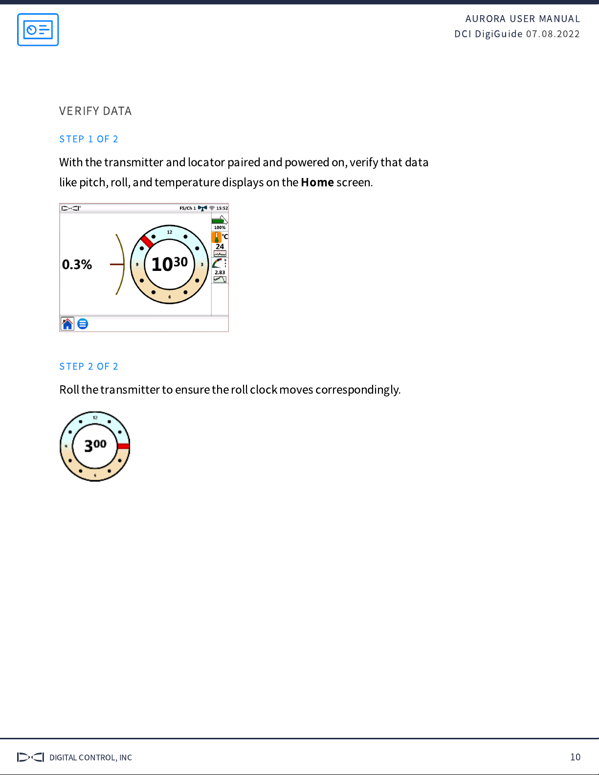
STEP 1 OF 2
With the transmitter and locator paired and powered on, verify that data
like pitch, roll, and temperature displays on the
Home
screen.
STEP 2 OF 2
Roll the transmitter to ensure the roll clock moves correspondingly.

AURORA USER MANUAL
DCI DigiGuide 07.08.2022
DIGITAL CONTROL, INC 11
During Drilling
BASIC OPERATION
STEP 1 OF 3
Data displays on the
Home
screen as soon as the locator receives data from
a transmitter.
1. Status bar
2. Transmitter (Tx) pitch
3. Tx roll
4. Home icon (shown active)
5. Main Menu icon
6. Tx battery
7. Tx temp and temp history
8. Fluid pressure and FP history (if applicable)
9. Locator type / Telemetry channel
10. Telemetry signal strength
11. Wi-Fi connection
12. Time
AURORA USER MANUAL
DCI DigiGuide 07.08.2022
DIGITAL CONTROL, INC 12
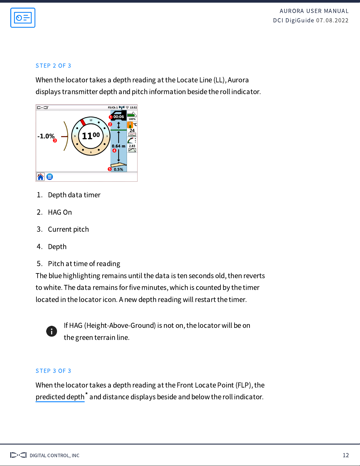
STEP 2 OF 3
When the locator takes a depth reading at the Locate Line (LL), Aurora
displays transmitter depth and pitch information beside the roll indicator.
1. Depth data timer
2. HAG On
3. Current pitch
4. Depth
5. Pitch at time of reading
The blue highlighting remains until the data is ten seconds old, then reverts
to white. The data remains for
fi
ve minutes, which is counted by the timer
located in the locator icon. A new depth reading will restart the timer.
If HAG (Height-Above-Ground) is not on, the locator will be on
the green terrain line.
STEP 3 OF 3
When the locator takes a depth reading at the Front Locate Point (FLP), the
and distance displays beside and below the roll indicator.predicted depth*
AURORA USER MANUAL
DCI DigiGuide 07.08.2022
DIGITAL CONTROL, INC 13
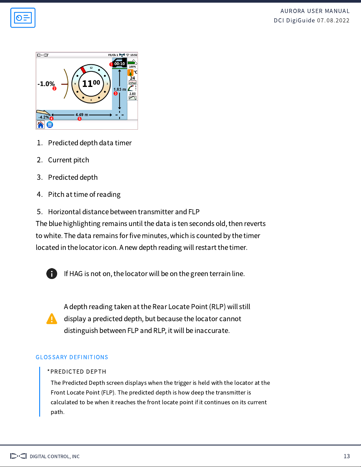
1. Predicted depth data timer
2. Current pitch
3. Predicted depth
4. Pitch at time of reading
5. Horizontal distance between transmitter and FLP
The blue highlighting remains until the data is ten seconds old, then reverts
to white. The data remains for
fi
ve minutes, which is counted by the timer
located in the locator icon. A new depth reading will restart the timer.
If HAG is not on, the locator will be on the green terrain line.
A depth reading taken at the Rear Locate Point (RLP) will still
display a predicted depth, but because the locator cannot
distinguish between FLP and RLP, it will be inaccurate.
GLOSSARY DEFINITIONS
*PREDICTED DEPTH
The Predicted Depth screen displays when the trigger is held with the locator at the
Front Locate Point (FLP). The predicted depth is how deep the transmitter is
calculated to be when it reaches the front locate point if it continues on its current
path.

AURORA USER MANUAL
DCI DigiGuide 07.08.2022
DIGITAL CONTROL, INC 14
10-2-7 ROLL METHOD
STEP 1 OF 10
Switching bands on the transmitter may provide better data, better depth,
and/or better locate results as interference conditions change.
This procedure requires roll data from the transmitter. If you need to change
bands on the transmitter but do not have roll data, see
Changing Bands
Using RRS Method
under
Advanced Topics
.
Roll o
ff
set must be disabled before changing bands.
STEP 2 OF 10
On the
Main
menu, tap
XR
.
STEP 3 OF 10
Tap
XR
in the task bar.
STEP 4 OF 10
Tap
Start
for
10-2-7 roll
method
.
STEP 5 OF 10
Tap
Start
to begin on-
screen instructions.

AURORA USER MANUAL
DCI DigiGuide 07.08.2022
DIGITAL CONTROL, INC 15
STEP 6 OF 10
Rotate until the transmitter clock falls within the
fl
ashing blue zone
indicated on the screen. Wait until timer expires. Repeat until 10-2-7
sequence is completed.
If any rotation is not completed within the prescribed time, or if
any rotation continues for more than one full revolution, the
transmitter band change is canceled.
STEP 7 OF 10
When the procedure is
fi
nished, the transmitter changes bands, causing
transmitter data to disappear. This may cause a failure notice to appear
even if the band change was successful. Always rely on the locator operator
to verify a band change.
Data will not disappear after a band change when using a
Falcon Sub-k Rebar transmitter.
STEP 8 OF 10
The locator operator should now change to the other paired and calibrated
band.

AURORA USER MANUAL
DCI DigiGuide 07.08.2022
DIGITAL CONTROL, INC 16
If the locator operator has not calibrated the second band,
depth readings will not be correct.
STEP 9 OF 10
Tap
Exit
, then
Main
menu.
Tap
XR
again in the
Applications
tab to close it.
STEP 10 OF 10
Tap
Home
to view transmitter data.

AURORA USER MANUAL
DCI DigiGuide 07.08.2022
DIGITAL CONTROL, INC 17
Post Drilling
CLEANING
STEP 1 OF 2
Hold the power/screen lock button on the side for approximately two
seconds to lock the screen for cleaning.
STEP 2 OF 2
Use a micro
fi
ber or soft cotton cloth with water and a mild liquid detergent
to clean the screen and case.
Commercial cleaning products will damage the screen
’
s
protective coating.
Do not pressure wash.
STORAGE
STEP 1 OF 2
Carefully remove and store the antenna in the carry case to prevent
damage.
STEP 2 OF 2
If the remote display is installed in the drill console, place the protective
plastic cover over the screen.
If the display can be removed from the rig, store it in the system carry case
away from impact, moisture, and excessive temperatures.
AURORA USER MANUAL
DCI DigiGuide 07.08.2022
DIGITAL CONTROL, INC 18
Storage and transportation temperature must remain within
-40°
‒
°F (-40°
‒
°C).

AURORA USER MANUAL
DCI DigiGuide 07.08.2022
DIGITAL CONTROL, INC 19
Advanced Topics
SET DATE AND TIME
STEP 1 OF 4
Tap
Main
menu.
STEP 2 OF 4
On the
Settings
tab, tap
Device
.
STEP 3 OF 4
Tap
Calendar
and use the
drop-down menus to set the
date, time, and time zone.
STEP 4 OF 4
Tap to return to the
Home
screen.
SET UNITS
STEP 1 OF 4
Tap
Main
menu.
STEP 2 OF 4
On the
Settings
tab, tap
Device
.

AURORA USER MANUAL
DCI DigiGuide 07.08.2022
DIGITAL CONTROL, INC 20
STEP 3 OF 4
Tap the
Framing Square
icon and use the drop-down
menus to set units for
temperature, distance,
pitch, pressure (for
fl
uid
pressure transmitters), and
force (for TensiTrak only).
STEP 4 OF 4
Tap to return to the
Home
screen.
CHANGE LOCATOR TYPE
STEP 1 OF 3
Tap
Main
menu.
Tap the
Locator
.
STEP 2 OF 3
Use the drop-down menu to select your locator.
Other Digital Control Industrial Equipment manuals


