Zakład Wytwórczy Aparatów Elektrycznych Sp. z o.o.
8
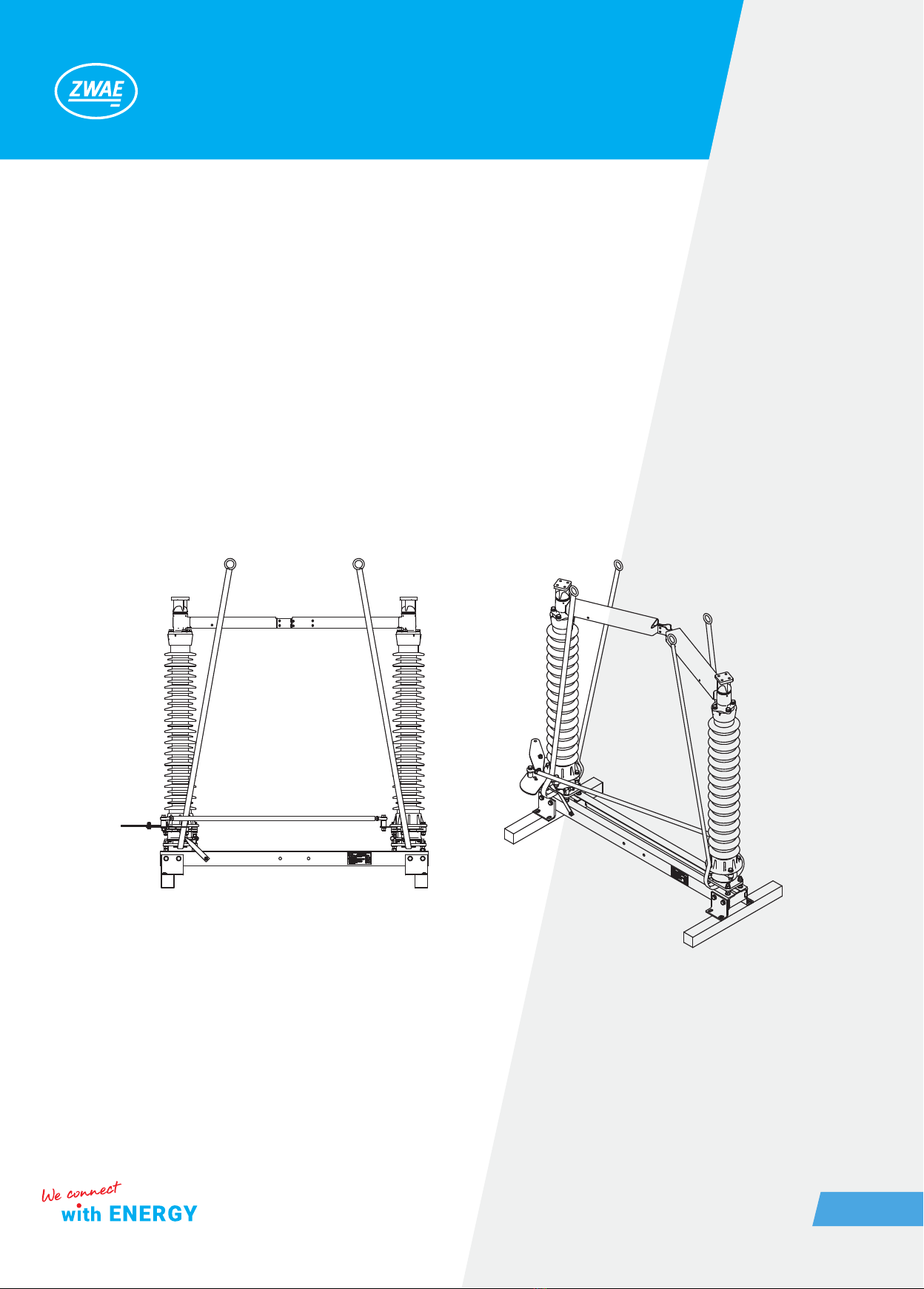
3. INSTALLATION AND ADJUSTMENT
The delivered disconnector is completely regulated and ready to work. Assembly is reduced to:
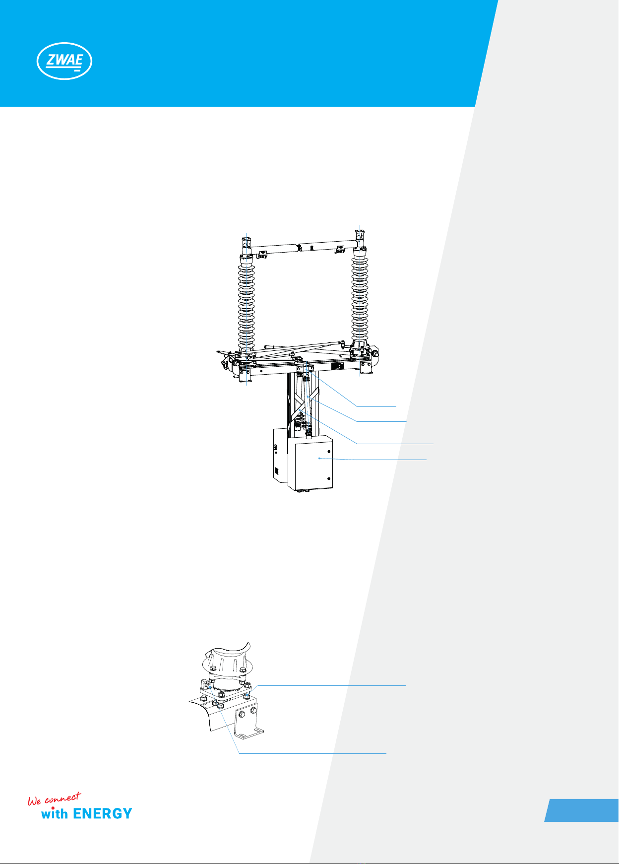
a) installation poles on a supporting structure,
b) attaching supporting construction for the operating mechanisms,
c) installation of operating mechanisms,
d) poles coupling and regulation,
e) earthing switches coupling,
f) earthing switches regulation,
g) grounding the base frame and operating mechanisms.
3.1. Preparing contact surfaces
Contacts resistance depends primarily on the quality and cleanliness of the contact surface. These surfaces
should be very precisely prepared. The method of preparing aluminum and silver contacts surfaces is de-
scribed below:
• aluminum – aluminum connection
Remove the oxide layer from the contact surface with a wire brush. After this treatment, the surface should be
matt gray, devoid of shiny areas. Clearly remove shavings and aluminum dust from the surface, for example by
lubricating with acid-free grease and then removing it. After this treatment, the surface should be greased with
acid-free grease to protect it from oxidation of aluminum. The prepared surface should not be exposed to the
atmosphere longer than the time needed to prepare the cooperating surface.
• copper – silver connection
The copper surfaces should be cleaned of oxides with a brass wire brush and then proceed as for the aluminum
surface. Silver surfaces do not need to be cleaned with a brush, but they can be cleaned with a mild abrasive,
for example steel wool. After cleaning, cover the surface with a thin layer of acid-free grease.
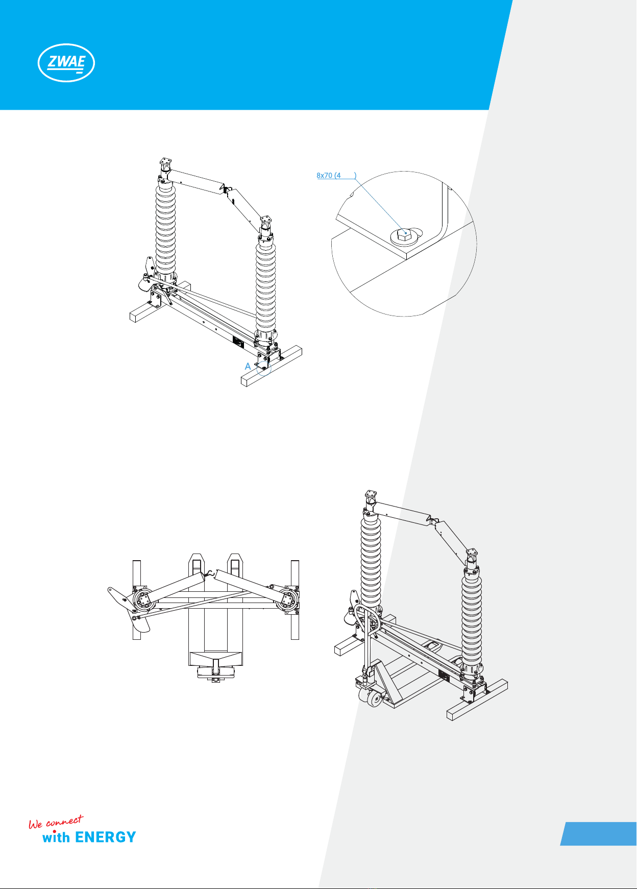
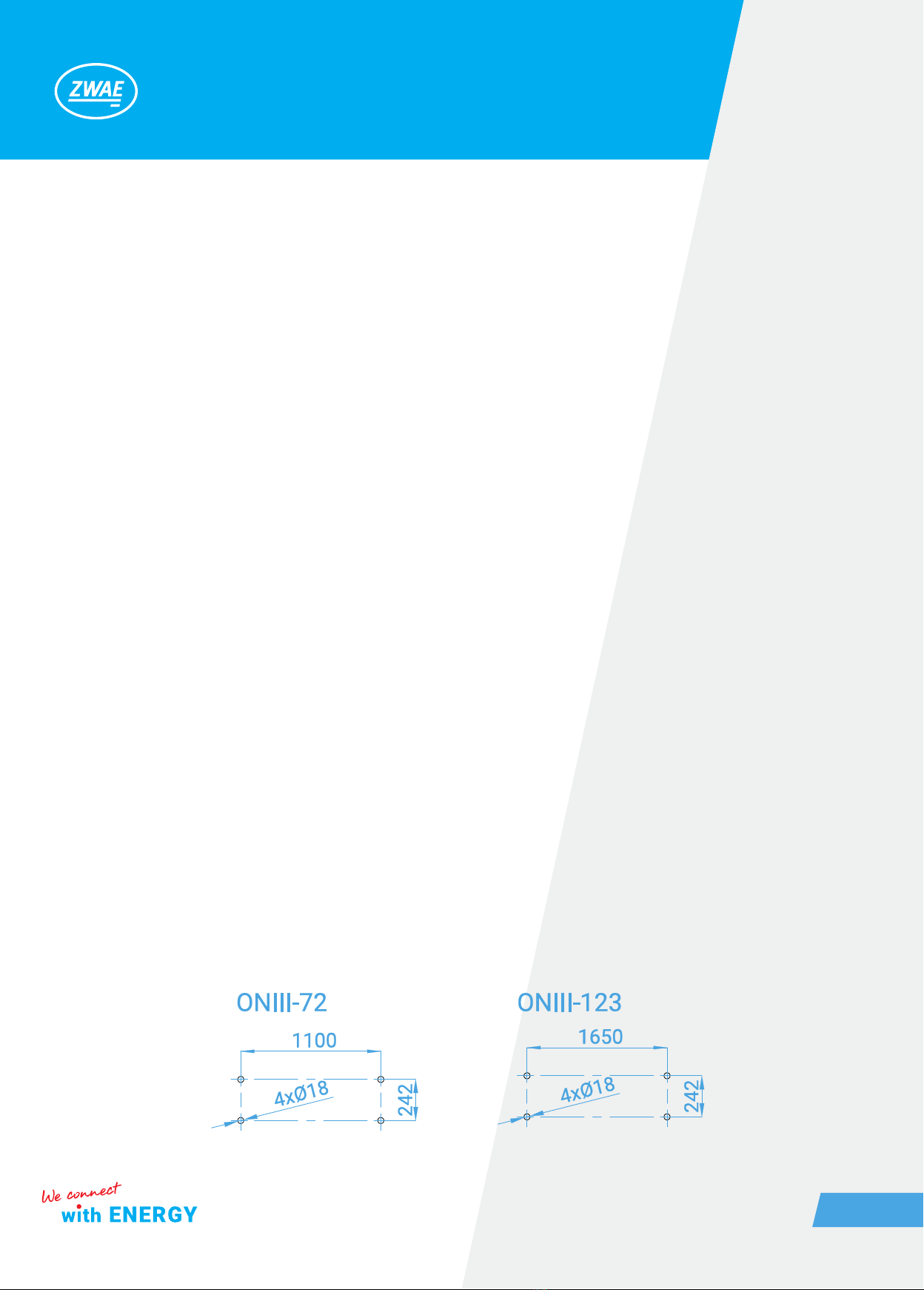
3.2. Poles adjustment
The disconnector poles should be placed on the supporting structure, which has mounting holes in accordance
with the drawing below.