Digital Control DigiTrak Falcon F1 User manual
- 1 -
© 2021 Digital Control Incorporated
All rights reserved. 402-2054-00-A English
digital-control.com
Falcon Quick Start Guide
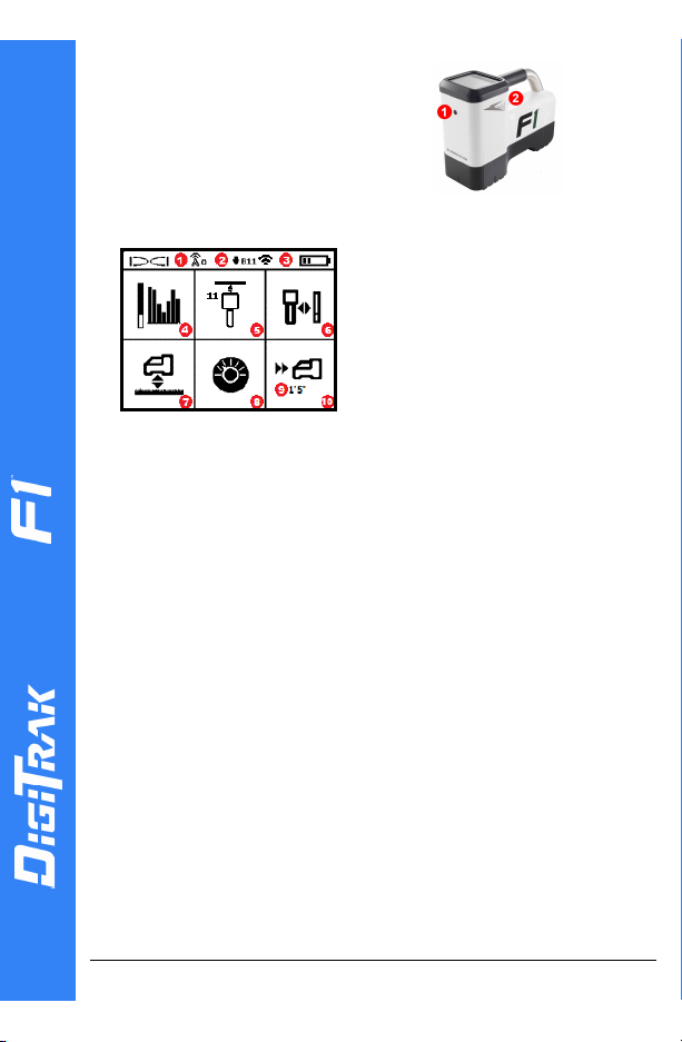
1. IRport
2. Trigger
Power On the Locator
1. Install the battery pack and hold
the trigger for one second.
2. Click to acknowledge the warning.
3. Click twice to open the Main menu.
Main Menu
1. Telemetry channel
2. Transmitter (Tx) band down
3. Tx Power Mode (left)
Locator battery strength (right)
4. Frequency Optimization (FO)
5. Tx Quick Scan Pair (QSP)
6. Calibration
7. HAG and TrakStand
8. Settings
9. Target depth (displays when set)
10. Target Steering
To open the Main menu from the Locate Mode screen, click the
trigger. Click to move through the menu and screens. Hold the
trigger briefly and release to make a selection. Power Off is on the
next screen. After 6 seconds idle, the screen returns to Locate
Mode.
Steps Required Before Drilling
1. Optimize and Measure Active Interference
The FO scans 60+ frequencies and selects the quietest frequencies
to optimize the signal for band 11.
There are two methods to optimize frequency bands:Quick Scan
Pair and Scan, Pick, and Pair. To decide which method to use,
visually inspect entire site for sources of interference, such as
traffic loops and other utilities. Pay attention to the area around
the deepest part of the bore for sources of interference.
Basic Method:Quick Scan Pair (QSP)
At jobsites with minimum active interference, optimize band 11. The
locator does not display noise during QSP optimization.
a. With the Tx off, go to the spot on the bore path with highest
suspected interference or the deepest part of the bore.
b. Select Quick Scan Pair from the Main menu.
The screen displays the band and preset power modes and is ready to
pair. To learn more about interference and changing the preset power
modes, see the DCI DigiGuide App.
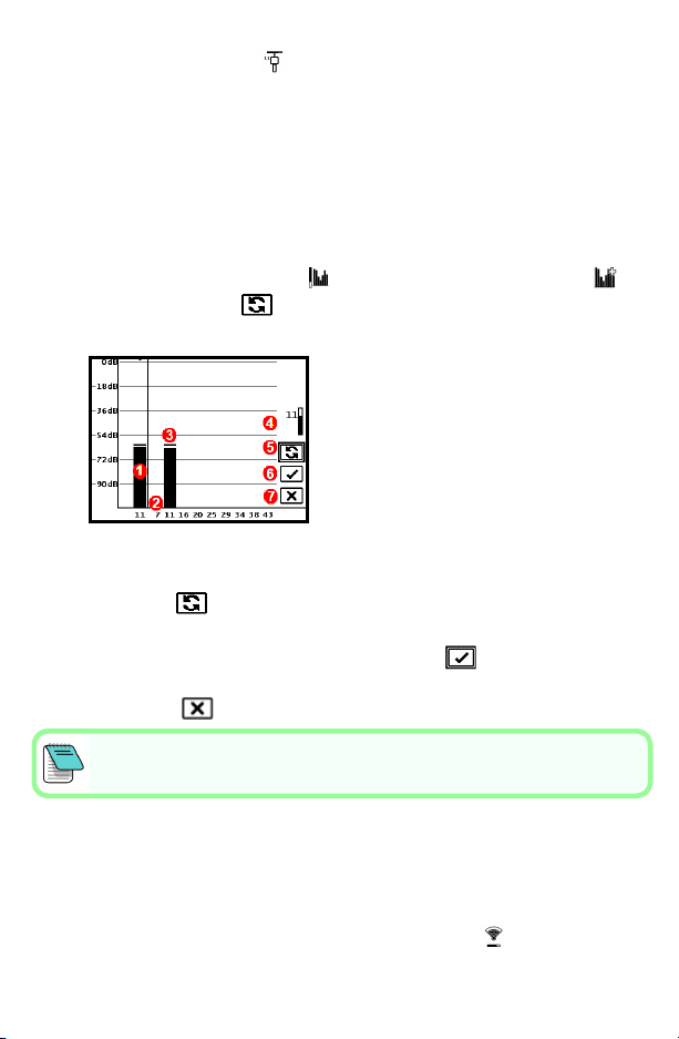
Advanced Method:Scan, Pick, and Pair
At jobsites with challenging interference, use Frequency Optimization
(FO) to show the active interference (noise) as you walk the bore path.
The FO will show the previously saved and current noise level for band 11.
a. With the Tx off, select Tx/FO from the Main menu, select FO ,
and then select Scan .
b. Walk and scan the drill path to find areas with the highest noise levels.
1. Currently paired Down band
2. Band numbers
3. Maximum noise reading line
4. Down band (*Quick Select option)
5. Rescan
6. Pair
7. Exit/Cancel
FO Results
c. It is important to return to the point on the bore path with the highest
noise. Rescan to optimize band 11.
d. You can do one of the following:
•To pair the newly optimized band, select Pair .
• To cancel and return to the Locating Mode screen without optimizing,
select Cancel .
The lower frequencies in band 11 will be less affected by rebar and passive
interference. To learn more, search the DCIDigiGuide App for "interference."
2. Pair the Locator with the Transmitter (Tx)
Tx's have two power levels: Standard and Low. Standard power operates
deeper. Low power has faster data speed and longer battery life.
a. Install transmitter (Tx) batteries and endcap.
b. To change the power level, select Tx Power Mode . To learn more,
search the DCI DigiGuide App for "power modes."
- 2 -

c. Position the Tx's infrared (IR) port near the locator's IR port.
Falcon locators with programmable power mode override
any other selection method when used with a V2 Tx.
d. Select Tx Pairing and hold the Tx in place until the check mark
appears (5 to 10 seconds) and the locator beeps.
e. After a successful pairing, the locator displays the Down band with the
power mode.
f. Click to confirm the power level. The 1 pt calibration menu opens.
3. Calibrate
Calibrate in an interference-free environment
after any pairing or Tx Power Mode change.
a. Place the Tx in a housing on level ground and
measure 10feet from the nearest edge of the
locator to the center of the transmitter.
b. Select Continue to calibrate. Do NOTmove
the locator during calibration. The AGRscreen opens.
c. Check the default Above Ground Range (AGR) with a tape measure to
verify depth readings on each band at least two depths (5 ft and 15 ft).
Distance readings should be within ±5%. Select Exit .
If the roll indicator on the Locate Mode screen displays a triangle error symbol
that band has not been calibrated. Go to the Calibration menu and complete a 1
pt calibration for that band.
Settings Menu
Use the Settings menu to set the depth units, pitch units, roll offset,
telemetry channel, Target Steering depth, leveling, LOC security settings,
contrast, and Cal history. Set the remote display to match locator settings.
Height-Above-Ground (HAG) Menu
Height-Above-Ground (HAG) is the distance from the ground to the
bottom of the locator while it is held or on a TrakStand. Enabling HAG
on the Main menu lets you take accurate below-ground depth
measurements without having to place the locator on the ground.
Target Steering assumes the locator is on the ground unless TrakStand HAGis
enabled. For more information, search the DCI DigiGuide App for "Target
Steering"and "TrakStand."
- 3 -
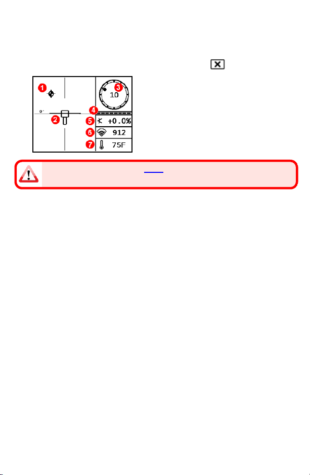
Locate Mode Screen
The Locate Mode screen appears if any menu is idle for more than 6 to 7
seconds, or immediately after a selection. To return to the Locate Mode
screen from any other screen, select Cancel or Exit .
1. Locate point (ball)
2. Locator (box) with LL centered
3. Roll indicator and value
4. Roll/pitch update meter
5. Tx pitch
6. Tx Power Mode and signal strength
7. Tx temperature
Transmitter and locator must be Paired and on the same band before data will
display. To learn more, search the DCI DigiGuide App for "remote displays."
Basic Locating
1. Find the Front Locate Point (FLP) and Rear Locate Point (RLP) by
centering the target ball in the box. Mark the positions.
2. At the FLP, hold trigger for predicted depth reading. The Reference
indicator Ricon will appear. The Locate Line (LL) may not appear if
this step is skipped.
3. Find the LL by centering the line in the box between the FLP and RLP.
See Locate Mode screen on previous page.
4. View depth by holding the trigger at the LL on the line between the
FLP and RLP.
5. To improve depth/data readings, hold the trigger five or more seconds
to enable Max Mode. For more information, search the DCI
DigiGuideApp for "Max Mode."
Signal Attenuation
If the signal strength flashes, this indicates extreme interference. Depth
and locate points may be comprised and the locator will not calibrate.
If the signal strength is not flashing but an Aicon appears in the roll
indicator at depths shallower than 8feet, this is normal, and you can
ignore the Awarning.
- 4 -

Transmitter Signal Field Geometry
Level Transmitter
1. Side view
2. RLP: Rear Locate Point
3. LL: Locate Line
4. FLP: Front Locate Point
Pitched Transmitter
1. Bird's-eye view (top down)
2. Drill rig
3. Side view (underground)
4. RLP: Rear LocatePoint
5. LL:Locate Line
6. Transmitter (Tx)
7. Bore path
8. FLP:Front Locate Point
FLP and RLP are not equidistant from the LL when the transmitter is
pitched. For more information, search the DCI DigiGuide App for "Steep
and Deep."
Bird’s-Eye View on Locate Mode Screen
1. Locate Line Yaw
2. Locator (box)
3. Locate Line (LL)
4. Attenuation
5. Tx
6. Locator
Locate Mode Screen
(Line-in-the-Box at LL)
Actual Position of
Locator and
Transmitter
- 5 -
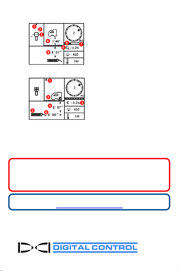
Depth and Predicted Depth Readings
Trigger held at LL
1. Locate Point (FLP or RLP)
2. Bird's-eye view
3. Line-in-the-Box at LL
4. HAG on
5. Max Mode timer
6. Max Mode icon
7. Roll Offset
8. Tx depth
Depth Screen (Line-in-the-Box at LL)
Trigger held at FLP
1. Reference Lock indicator
2. HAGoff
3. Pitch
4. Predicted depth of Tx*
5. Tx battery strength
6. Horizontal distance between Tx
and FLP*
* Only valid at FLP. Invalid at RLP.
Predicted Depth Screen (Ball-in-the-Box at FLP only)
The predicted depth is the depth the transmitter is calculated to be when
it reaches the Front Locate Point (FLP) if it continues on the current path
and pitch.
For detailed information, install the DCI DigiGuide App from your smart device's
App store or download the Operator's Manuals from digital-control.com.
Printed manuals are available upon request.
If you have questions, contact your regional DCI office or Customer Service
at1.425.251.0559 or 1.800.288.3610 US/CA.
Watch our DigiTrak training videos at
www.YouTube.com/DCIKent
DCI, the DCI logo, DigiTrak, DigiTrak Falcon, F1, andTarget Steering are registered trademarks and Ball-
in-the-Box, Ball-in-the-Box logo, Ball logo, Box logo, DigiGuide, Falcon Logo, HAG, Max Mode and
TrakStand are common law trademarks of Digital Control Incorporated. Additional trademark
registrations are pending. U.S. and foreign patents apply to the product covered by this guide. For
details, please visit www.DigiTrak.com/patents.
Printed:
5/5/2021
- 6 -
Table of contents
Other Digital Control Industrial Equipment manuals


