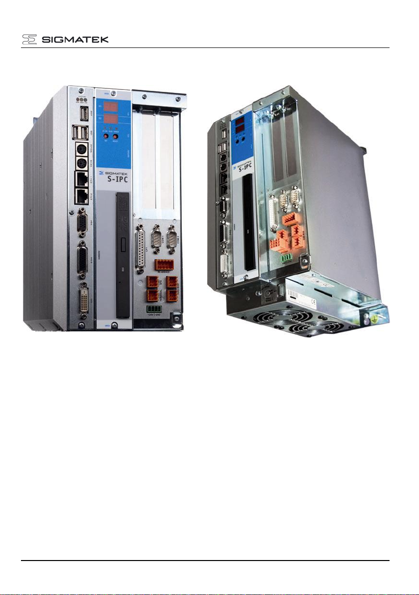
S-IPC INTEL®ATOM DUAL CORE
Page 2 21.02.2014
Contents
Contents..................................................................................................... 2
Technical Data ........................................................................................... 3
Postcodes................................................................................................... 6
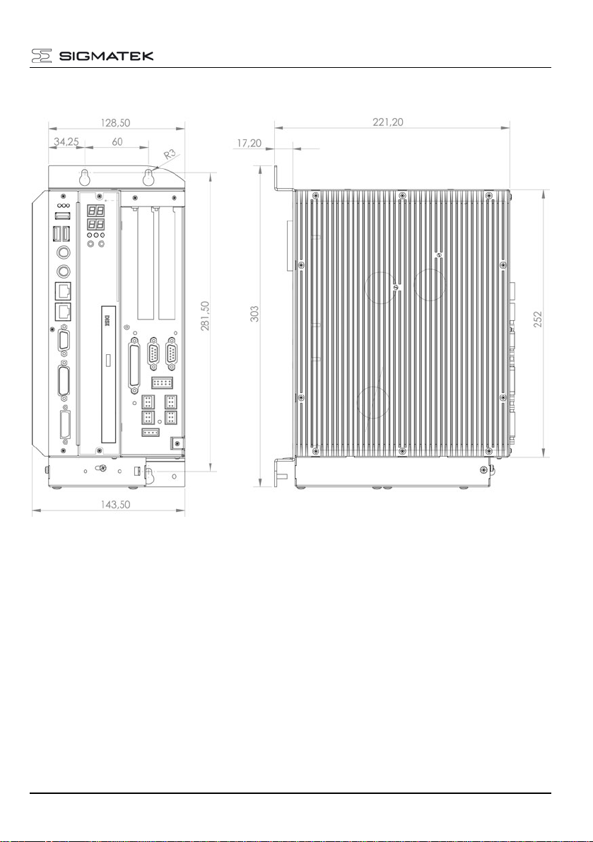
Mechanical Dimensions (with fan and heat sink) .................................. 7
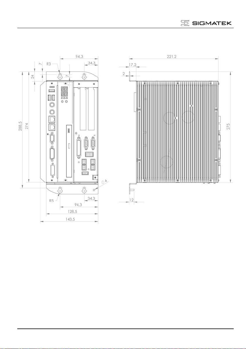
Mechanical Dimensions (with heat sink) ................................................ 8
Mechanical Dimensions (mounts) ........................................................... 9
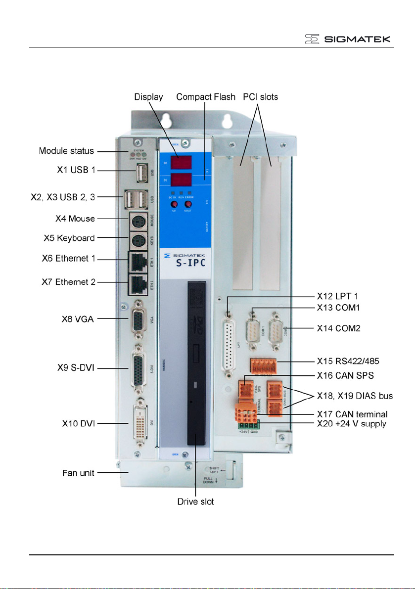
Connector Layout.................................................................................... 10
Front connectors.................................................................................... 11
Bottom Connectors................................................................................ 17
Status Displays........................................................................................ 18
Sigmatek Components............................................................................ 20
S-IPC Status............................................................................................. 21
Exchanging the CompactFlash Card..................................................... 24
Exchanging the Battery .......................................................................... 25
Buffer Battery........................................................................................... 26
Exchanging the Fan ................................................................................ 27
Mounting PCI Cards ................................................................................ 28
Exchanging the Drive unit...................................................................... 30
Cooling ..................................................................................................... 31
Mounting Instructions............................................................................. 31
Wiring Guidelines.................................................................................... 32
1. Earth Connection............................................................................... 32
2. Shielding............................................................................................ 33
3. ESD Protection .................................................................................. 33
4. DIAS Bus Termination....................................................................... 34
5. DIAS bus connection to C-DIAS modules......................................... 34
6. Connecting DIAS Modules ................................................................ 35
7. CAN Bus Termination........................................................................ 36
8. USB Interface Connections ............................................................... 37
9. RS485 Bus Termination .................................................................... 38
Pictures of the S-IPC............................................................................... 39