Contents
v
DIGITAL Server 3100/3200
DIGITAL Server7100
DIGITAL Server 7100R
Figures
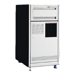
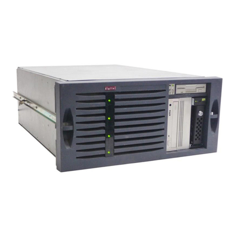
Typical DIGITAL Server 7100R.......................................................................................... viii
2-1. SCU Main Menu Options........................................................................................... 2-5
4-1. DIGITAL Server Component Information.................................................................... 4-7
5-1. Digital Server 7100R IPB (1 of 2)............................................................................... 5-3
5-1. Digital Server 7100R IPB (2 of 2)............................................................................... 5-5
5-2. Removing the Front Bezel........................................................................................... 5-9
5-3. Unlocking and Removing the Top Cover ................................................................... 5-11
5-4. Installing and Locking the Top Cover......................................................................... 5-12
5-5. Server Top View......................................................................................................... 5-14
5-6. Server Front View...................................................................................................... 5-16
5-7. Server Rear View....................................................................................................... 5-18
5-8. Main Logic Board Connectors.................................................................................... 5-20
5-9. Main Logic Board Components.................................................................................. 5-22
5-10. Processor Module Components and Connectors.................................................... 5-24
5-11. Main Logic Board Switch Location............................................................................ 5-27
5-12. Processor Module Switch Location.......................................................................... 5-29
5-13. DIMM Bank Locations.............................................................................................. 5-31
5-14. Removing and Replacing the Diskette Drive............................................................ 5-36
5-15. Removing and Replacing the CD-ROM Drive.......................................................... 5-38
5-16. Removing and Replacing the SBB Mounting Bracket Assembly.............................. 5-40
5-17. Removing and Replacing the Speaker...................................................................... 5-42
5-18. Removing and Replacing the Rear Bracket Assembly ............................................. 5-44
5-19. Removing and Replacing the Main Logic Board....................................................... 5-46
5-20. Replacing the Server Battery/RTC........................................................................... 5-48
5-21. Removing and Replacing the Storage Backplane..................................................... 5-50
5-22. Removing and Replacing the Power Distribution Board............................................ 5-52
5-23. Hot Swapping a Power Supply................................................................................. 5-54
5-24. Hot Swapping a Cooling Fan.................................................................................... 5-56
6-1. Removing the Terminator Card.................................................................................. 6-6
6-2. Installing a Processor Module.................................................................................... 6-8
6-3. Removing the Processor Module............................................................................... 6-10
6-4. Removing the Retaining Clip...................................................................................... 6-11
6-5. Removing the Processor/Heat Sink Assembly........................................................... 6-12
6-6. Installing the New Processor...................................................................................... 6-13
6-7. Installing the Retaining Clip........................................................................................ 6-14
6-8. Installing a VRM......................................................................................................... 6-15
6-9. Installing the Processor Module................................................................................. 6-16
