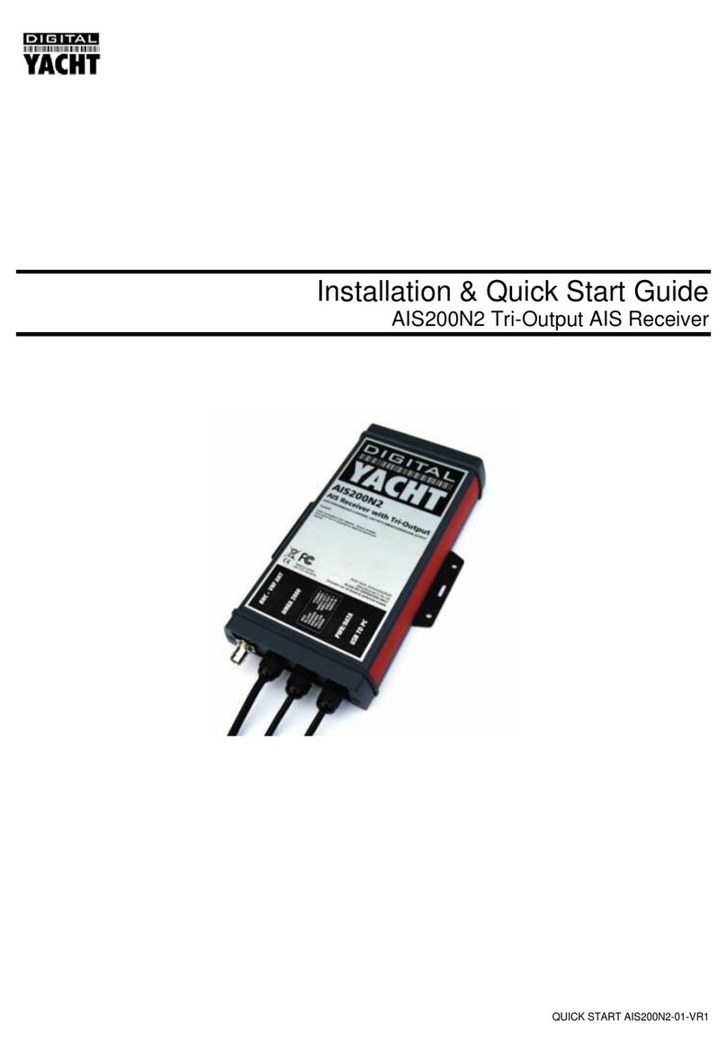
DIGITAL YACHT AIS200N2NET Datasheet

QUICK START AIS200N2NET-01-VR1
Installation & Quick Start Guide
AIS200N2NET Tri-Output AIS Receiver

DIGITAL YACHT LTD
AIS200N2NET Quick Start Guide
1. Introduction
Congratulations on the purchase of your AIS200N2NET AIS Receiver. It is recommended that your receiver is installed by
a professional installer.
Before operating the unit you should familiarise yourself with the complete user manual supplied with the
product.
2. Before you start
You will need the following items and tools to complete the installation:
The AIS200N2NET Receiver
Dedicated AIS/VHF antenna or existing VHF antenna and splitter
Access to 12V or 24V DC power supply where the unit is to be installed.
M3 or M4 screws or other fixings appropriate to the mounting location.
To display the AIS targets and data you will need:
Suitable PC Navigation software running on a PC with Microsoft Windows XP®/ Windows Vista®/ Windows 7®with
a free USB port.
Or a suitable dedicated chart plotter that can read and display AIS data via NMEA0183 or NMEA2000
3. Installation
Before starting installation select a suitable location for the AIS Receiver. The unit is water resistant; however it should be
installed below deck in a dry location. When locating the unit you should consider:
Routing of power and antenna cables to the unit.
Provision of sufficient space behind the unit for cable connections.
Routing of data connections to PC or chart plotter from the unit.
Maintaining the compass safe distance of 0.5m.
Installation Step 1
Run the VHF antenna co-axial cable to the AIS Receiver and terminate with a BNC connector (Bayonet)
Run the interfacing cables to the AIS Receiver; NMEA0183, NMEA2000 or USB
Do not make any connections yet
The USB Interface Standard specifies that USB cables should be no longer than 5m without using a
special powered USB extender cable –ensure that the total USB cable length from the AIS Receiver to
the PC is < 5m.
Installation Step 2 –Mechanical Fixing
Access to the fixing holes is achieved by removal of the two red decal strips down each side of the
AIS200N2NET. Once fixed in place, the red decal strips can be clicked back in place.
Secure the AIS Receiver to a flat surface in the selected location. Use four M4 wood screws or other fixings
suited to the material the unit is being fixed to. The unit may be installed in any orientation.
DIGITAL YACHT LTD
AIS200N2NET Quick Start Guide
Fixing location drawing
Once the unit is secured, connect the AIS/VHF antenna. Ensure the bayonet connection is fully made; should feel
a slight click as the BNC locks.
Installation Step 3 –Power
Provide power connections to the unit. Power is connected to the ten core PWR/DATA cable on the Red and
Black wires. The Red wire is the positive (+) connection. The Black wire is the negative (-) connection.
Connect the stripped wires to the nearest source of primary 12V or 24V DC power. Ensure that the supply is
connected via the supplied 1A fuse or suitable circuit breaker. Add the fuse in the positive power connection
to the unit if necessary.
The AIS200N2NET Receiver can be connected to other AIS compatible equipment via the NMEA0183
connections on the PWR/DATA cable, via the Male “Micro” NMEA2000 connector or via the USB interface (most
common connection for PCs). The following steps explain how to connect to each type of interface.
Installation Step 4 –NMEA 0183
The most common connection to a dedicated chart plotter is to take the NMEA Output 1 (Orange+ and Brown –)
from the AIS200N2Net and to connect it to a free NMEA Input on the plotter. You must then tell the chart plotter
that AIS data is connected to this port and set the baud rate to 38,400 Baud –the standard speed for AIS data.
Consult the instruction manual supplied with your Chart Plotter to understand how this is configured.
NMEA 0183 data from other equipment can be connected to either of the NMEA Inputs of the AIS200N2Net. This
is most commonly connected to NMEA Input 2 (Yellow+ and Green-) at the normal 4800 baud rate for NMEA
0183. This data is then multiplexed with the AIS data and output on the NMEA Output 1 and USB at 38,400 baud
–useful when connecting to equipment that only has one NMEA input or to a computer with limited USB ports.

DIGITAL YACHT LTD
AIS200N2NET Quick Start Guide
NOTE - Only NMEA messages with a valid checksum are passed through the AIS200N2NET and re-transmitted
with the AIS data. Some older NMEA0183 equipment may not include checksums which were added in NMEA
0183 Version 2.0.
The table showing what each of the 12 wires of the PWR/DATA cable does, is printed on the AIS200N2NET
Receiver and repeated below for your convenience;
AIS200N2NET Receiver PWR/DATA cable:
oRED - Power + (12v)
oBLACK - Power –(0v)
oORANGE - NMEA1 Out +
oBROWN - NMEA1 Out –(NMEA 1 is 38400 Baud)
oTURQUOISE - NMEA1 In +
oGREY - NMEA1 In –
oPINK - NMEA2 Out +
oVIOLET - NMEA2 Out –(NMEA 2 is 4800 Baud)
oYELLOW - NMEA2 In +
oGREEN - NMEA2 In –
oWHITE - Not Used
oBLUE - Not Used
Installation Step 5 –N2Net (NMEA2000)
The AIS200N2NET also has an N2Net connection which is Digital Yacht’s NMEA2000 compliant interface. To
connect to other NMEA2000 products, simply find or add a spare NMEA2000 “T” piece on the existing
NMEA2000 network and connect the receiver’s N2Net connector to the “T” piece.
The N2Net cable is just over 1m long and is terminated in an NMEA2000 Micro Male Connector.
The AIS200N2NET does not take any power from the NMEA2000 network and only outputs AIS data on to the
network, it does not input NMEA2000 data or provide any NMEA2000 to NMEA0183 conversion.
The list of AIS PGNs that the AIS200N2Net outputs is listed below;
PGN No.
PGN Title
129038
Class A Position Report
129039
Class B Position Report
129040
Class B Extended Position Report
129793
AIS UTC and Date report
129794
AIS Class A Static and Voyage Related Data
129800
AIS UTC/Date Inquiry
129801
AIS Address Safety Message
129802
AIS Broadcast Safety Message
129810
AIS Class B static data part B
129809
AIS Class B static data part A
129041
AtoN position report
Installation Step 6 –USB Connection to a PC
To install the drivers for the AIS200N2Net, insert the supplied CD-Rom and locate the “proAIS2 for AIT2000”
folder on the CD. Run the setup.exe program, which installs the proAIS2 software and the drivers. Once the
installation is completed, you can plug in the USB lead of the AIS200N2Net in to an available USB port on your
PC and the Windows “Found New Hardware Wizard” will be triggered and the correct drivers loaded. Make a note
of the COM port number that Windows allocates to the AIS200N2Net, which can be found in the Windows Device
Manager program under the “Ports (COM&LPT)” section or by running the proAIS2 software.

DIGITAL YACHT LTD
AIS200N2NET Quick Start Guide
The proAIS2 software is primarily designed for configuring the Digital Yacht AIT2000 Class B Transponder but it
can be used with the AIS200N2Net to check the if AIS Targets are being received. When you run the proAIS2
software you will see the AIS200N2Net listed as “AIS Virtual COM Port X” where X is the COM port number
allocated by Windows. This is the COM port that you will need to set in your Navigation software to read data
from the AIS200N2Net.
Click the “Connect” button and the proAIS2 program will start to receive data from the AIS200N2Net. Click on the
“Other Vessels” tab to display a list of the AIS targets being received. If you want a more graphical display of AIS
targets, install and run our free SmarterTrack Lite software also included on the CD-Rom.
If you are connected to the internet when you connect the USB lead of the AIS200Net to your PC for the first
time, Windows Vista and Windows 7 (not Windows XP) will automatically find the correct driver and download it
from the Microsoft website. This is useful if you try to install the AIS200N2Net and you do not have the supplied
CD-Rom with you. When using this automatic method of installing the drivers from the internet, the proAIS2
software is not installed. As it is only used for testing or diagnosing the installation this is not normally a problem.
Installation Step 7 –Checking Operation
As soon as 12v or 24v Power is connected to the AIS200N2NET Receiver, the unit will power up and the green
“POWER” LED on the front of the unit will light.

DIGITAL YACHT LTD
AIS200N2NET Quick Start Guide
Every time that the unit receives an AIS Target, the Yellow “DATA” LED will flash.
Assuming that the Yellow LED is flashing and you are receiving AIS targets, ensure that any equipment
connected to the AIS200N2Net on the NMEA0183, NMEA2000 and/or USB interfaces are receiving and
displaying AIS targets.
Installation is now completed
Table of contents
Other DIGITAL YACHT Receiver manuals

DIGITAL YACHT
DIGITAL YACHT AISNet+ Quick guide

DIGITAL YACHT
DIGITAL YACHT WL60 MK2 Quick guide

DIGITAL YACHT
DIGITAL YACHT ANT200 Datasheet

DIGITAL YACHT
DIGITAL YACHT iAIS Datasheet

DIGITAL YACHT
DIGITAL YACHT AIS200N2 Datasheet

DIGITAL YACHT
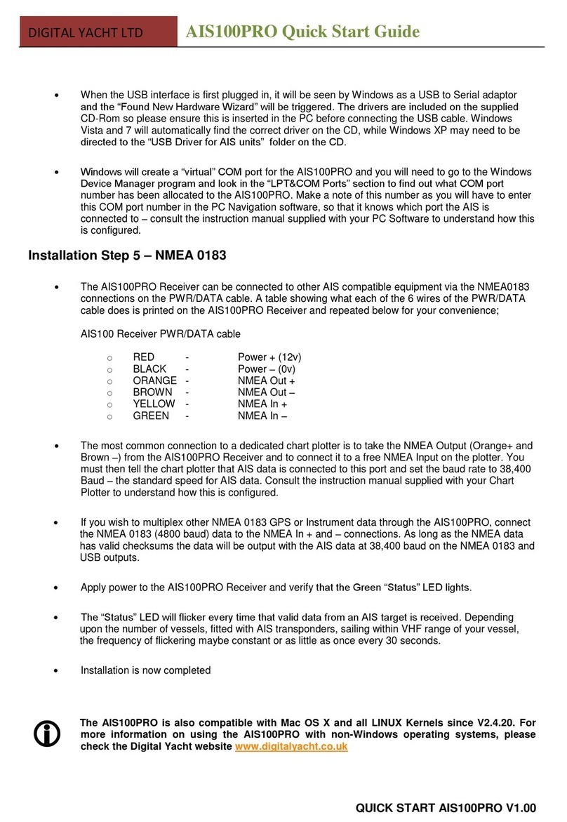
DIGITAL YACHT AIS100PRO Datasheet

DIGITAL YACHT
DIGITAL YACHT AIS100 User manual

DIGITAL YACHT
DIGITAL YACHT WL70 Quick guide

DIGITAL YACHT
DIGITAL YACHT AIS100USB Datasheet