Digitimer D188 User manual

Digitimer
D188
REMOTE ELECTRODE SELECTOR
OPERATOR’S MANUAL
For Research Use Only
“Digitimer” is a registered trade mark of Digitimer Limited

Digitimer Ltd –D188 Operator’s Manual Version 1.2
2
Digitimer Limited
37 Hydeway
Welwyn Garden City
Hertfordshire
AL7 3BE
UK
Tel: +44 (0)1707 328347
Fax: +44 (0)1707 373153
E-mail:
Website: www.digitimer.com

Digitimer Ltd –D188 Operator’s Manual Version 1.2
3
Table of Contents
Section 1 General Information .......................................................................................................................5
D188 Intended Usage & Description ..........................................................................................................5
Unpacking the D188....................................................................................................................................6
Supplied Accessories...............................................................................................................................6
Optional Accessories...............................................................................................................................6
Mains Connections .....................................................................................................................................6
Specifications..............................................................................................................................................7
Section 2 D188 Installation.............................................................................................................................9
Hardware Overview....................................................................................................................................9
D188 Front Panel ....................................................................................................................................9
D188 Rear Panel......................................................................................................................................9
D188 Digital Input Socket .....................................................................................................................10
Installing the D188 Control Software........................................................................................................10
Installing the D188 Remote Electrode Selector Hardware.......................................................................10
Section 3 Software Overview .......................................................................................................................12
Introduction..............................................................................................................................................12
Standby .................................................................................................................................................12
USB (Manual) Control Mode.................................................................................................................13
1:1 Digital Control Mode.......................................................................................................................13
4:8 Digital Control Mode.......................................................................................................................13
Delay/De-bounce Setting......................................................................................................................13
LED Control ...........................................................................................................................................13
Persistent Storage of Settings...............................................................................................................13
Section 4 System Operation .........................................................................................................................15
Introduction..............................................................................................................................................15
Connecting the D188 to an Electrical Stimulator......................................................................................16
Connecting to a Digitimer DS5, DS7A, DS7AH, DS7R or DS8R Stimulator ............................................16
Connecting to a Digitimer DS2A, DS3 or DS4 Stimulator......................................................................16
Connecting to other Stimulators ..........................................................................................................16
Connecting the D188 to Stimulating Electrodes.......................................................................................16
Using Multiple D188’s with a Single Stimulus Source...............................................................................17
Using Manual Control...............................................................................................................................17
Using External Digital Control...................................................................................................................17

Digitimer Ltd –D188 Operator’s Manual Version 1.2
4
1:1 Digital Control.................................................................................................................................17
4:8 Digital Control.................................................................................................................................18
Delay/De-bounce..................................................................................................................................18
Minimum Switching Times & Stimulus Pulse Duration.........................................................................18
Digital Control Voltage Requirements ..................................................................................................19
Using the API for Third Party Software Control........................................................................................19
Example Applications................................................................................................................................19
Application 1: Tactile stimulation of multiple digits (sequentially) across both hands........................19

Digitimer Ltd –D188 Operator’s Manual Version 1.2
5
Section 1
General Information
D188 Intended Usage & Description
The D188 Remote Electrode Selector can be used to direct electrical stimuli from a single stimulator to
one of up to eight pairs of stimulation electrodes. It is particularly useful in applications where a stimulus
needs to be presented to several stimulation sites, one site at a time, but only one stimulator is available.
Channel selection is controlled by TTL compatible digital inputs applied to the rear panel socket on the
D188 or manually via Windows compatible software (supplied). A pair of stimulus inputs is provided for
connection to a compatible electrical stimulator and there are eight pairs of stimulus outputs (channels),
numbered from 1 to 8, each associated with a green LED to show when they are active. These LED’s can
be turned off for situations where it is important that the subject does not know which channel is active.
Although the D188 has been designed with human applications in mind, the D188 is not a medical device,
so its use is limited to research applications. It should not be used for patient treatment or diagnostic
purposes.

Digitimer Ltd –D188 Operator’s Manual Version 1.2
6
Unpacking the D188
After unpacking the D188 Remote Electrode Selector from the shipping carton, please inspect each piece
for any sign of shipping damage. Please contact the carrier and your distributor, or Digitimer Limited,
immediately if there is any damage. Do NOT dispose of the shipping carton, as the carrier will want to
examine it in order to process a damage claim. Digitimer Limited and their distributors insure all
shipments to cover shipping damage.
It is also advisable to keep the shipping carton in the event that the instrument needs to be returned for
service.
Supplied Accessories
The following items should have been packed with your D188 Remote Electrode Selector:
12V Switched Mode Power Supply for 100V-240V input with plug adaptor(s).
USB Cable for host PC connection.
Quick Start Guide or Operator’s Manual.
Windows Compatible D188 Control App Software, including API for third party software control
(supplied on USB Stick).
Digital Communication Cable (1m long, 15-way “D” connector to 10 tinned wires).
Optional Accessories
D185-OC1 4mm Plugs (pair of 4mm touch proof plugs, compatible with the outputs on
Digitimer DS5, DS7A, DS7AH Isolated Stimulators).
NL844P Plugs (1.5mm DIN42802 plugs, available in red and black).
D185-HB4 Output Extension Cable (4mm touch proof plugs to 1.5mm touch proof sockets).
NL985P 2mm Plugs (pair of 2mm touch proof plugs for use with Digitimer DS2A, DS3 and DS4
Isolated Stimulators).
Stimulator connection cables: D188-09 (female 1.5mm touch-proof, 2m), D188-10 (female
1.5mm touch-proof, 50cm), D188-11 (2mm male touch-proof to 1.5mm female touch-proof,
50cm) and D188-12 (4mm male touch-proof to 1.5mm female touch-proof, 50cm.
Output Extension Cables: D188-13 (1m long) and D188-14 (2m long). Supplied in pairs for
extending the length of electrode leads fitted with 1.5mm DIN42802 touch-proof connectors.
Mains Connections
The D188 is shipped with a 100V-240V input power supply and plug adaptor plates for UK, European
(Schuko) or North American wall sockets. For countries that do not use one of these types of socket, we
recommend obtaining a compatible travel adaptor.

Digitimer Ltd –D188 Operator’s Manual Version 1.2
7
Specifications
Maximum Stimulus Input Voltage: 400V.
Maximum Stimulus Input Current: 1A.
Minimum Switching Interval: 1ms.
Digital Input Requirements: TTL Logic (5V).
Front Panel Connections:
Common (COM) Inputs: One red, one black 1.5mm DIN 42802 male sockets.
Stimulus Outputs: 8 pairs of red and black 1.5mm DIN 42802 male sockets.
Rear panel Connections:
USB Input (Type B Socket) for Win PC software control/setup.
Power Supply Input Socket
Digital Communication Socket (15-way Female “D” Connector).
Indicators:
8 Green LEDs –One per channel used to indicate the active channel.
Control Software:
Supplied on USB drive. Compatible with Windows 7 or higher.
Weight & Dimensions:
Size: 152 x 55 x 178 mm (w x h x d).
Weight: 500g (approx.).
Environmental:
Operating Range 10°C to 40°C 30 to 75%, non-condensing.
Storage Range -40°C to 70°C 10 to 100%, non-condensing.
Transport Range -40°C to 70°C 10 to 100%, non-condensing.

Digitimer Ltd –D188 Operator’s Manual Version 1.2
8

Digitimer Ltd –D188 Operator’s Manual Version 1.2
9
Section 2
D188 Installation
Hardware Overview
D188 Front Panel
D188 Rear Panel
LED Indicator
Electrode Connection Sockets
(8 pairs)
Stimulator Input Sockets (one pair)
USB “B” Socket
15-way Digital
Input Socket
12V Power Input
Socket
Digitimer Ltd –D188 Operator’s Manual Version 1.2
10
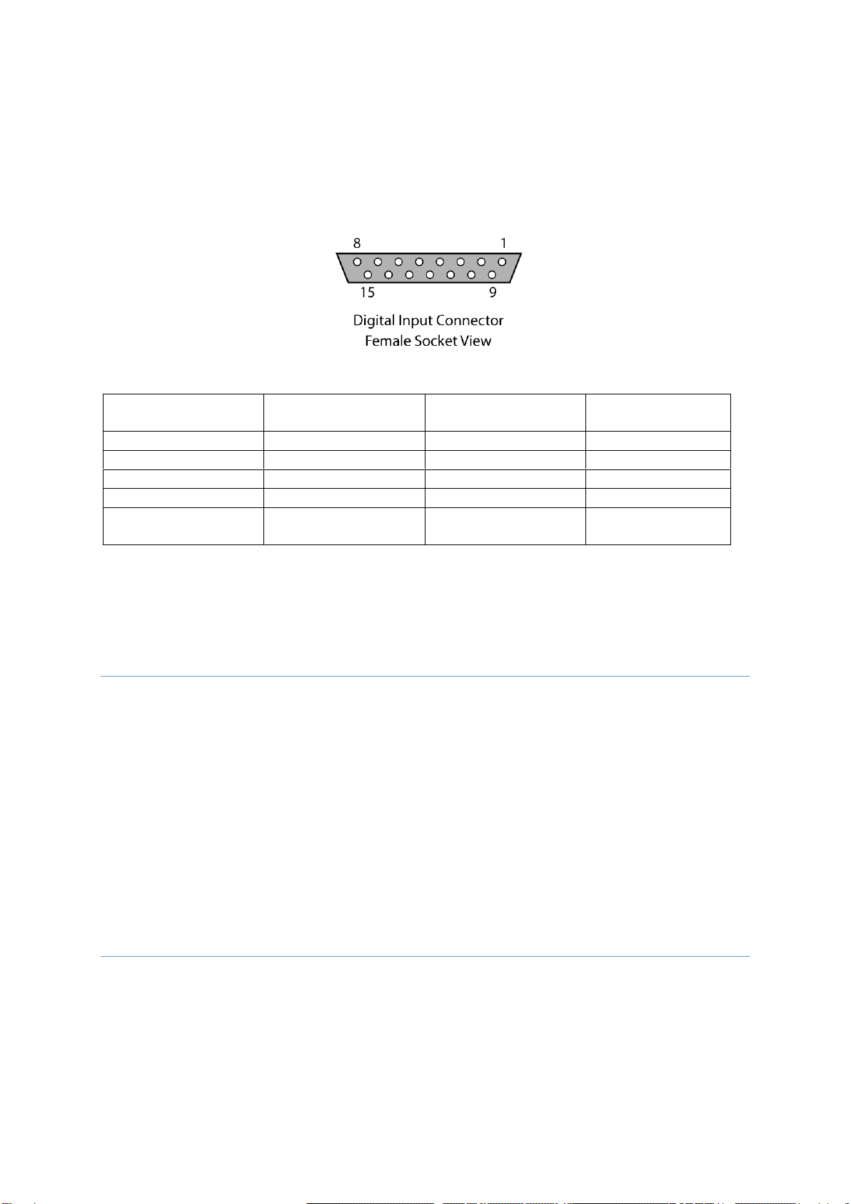
D188 Digital Input Socket
The D188 is fitted with a 15-way female “D” connector which is used for digital control. Digitimer
supplies a cable with the unit which has 10 tinned wires for user connection to a digital output device
fitted with screw terminals. The wiring details for the socket and cable are given below.
Pin
Function (Colour)
Pin
Function (Colour)
1
D0 (Black)
6
D5 (Green)
2
D1 Brown
7
D6 (Blue)
3
D2 (Red)
8
D7 (Violet)
4
D3 (Orange)
9
+5V (White)
5
D4 (Yellow)
10
GND/Cable Screen
(Grey/Black)
Note that pins 11 to 15 are unused. A +5V pin is made available for anyone wishing to use this for button
control of the D188 and is not needed for digital control.
Installing the D188 Control Software
The D188 Control Software is supplied on a USB flash drive and is compatible with personal computers
running Microsoft Windows 7 or higher.
1. Insert the USB stick and browse to the contents.
2. Double click on the D188 software installer file (*.exe) and follow in the installation prompts to
completion.
Installing the D188 Remote Electrode Selector Hardware
Once the software has been installed on the host PC, the D188 can be connected to the computer.
1. Connect the supplied USB cable between the D188 and a free USB port on the host PC.

Digitimer Ltd –D188 Operator’s Manual Version 1.2
11
2. Connect the 12V power supply adaptor to a powered wall socket the other end to the D188 rear
panel power input.
3. There may be a delay of up to a minute as the D188 device drivers are detected and installed by
the Windows operating system.
4. Once driver installation is complete, double click the D188App icon on the desktop to run the
control software.
5. If the software detects one or more D188’s, the device ID’s (serial numbers) will be shown in the
top left of each device’s D188 software panel. D188’s are always sorted with the lowest device
number at the top and the highest at the bottom.
6. If a D188 is not detected, the software will display “Waiting...”. If this happens, check the power
supply and USB cables are connected or try a different USB port and/or wall socket.
Digitimer Ltd –D188 Operator’s Manual Version 1.2
12
Section 3
Software Overview
Introduction
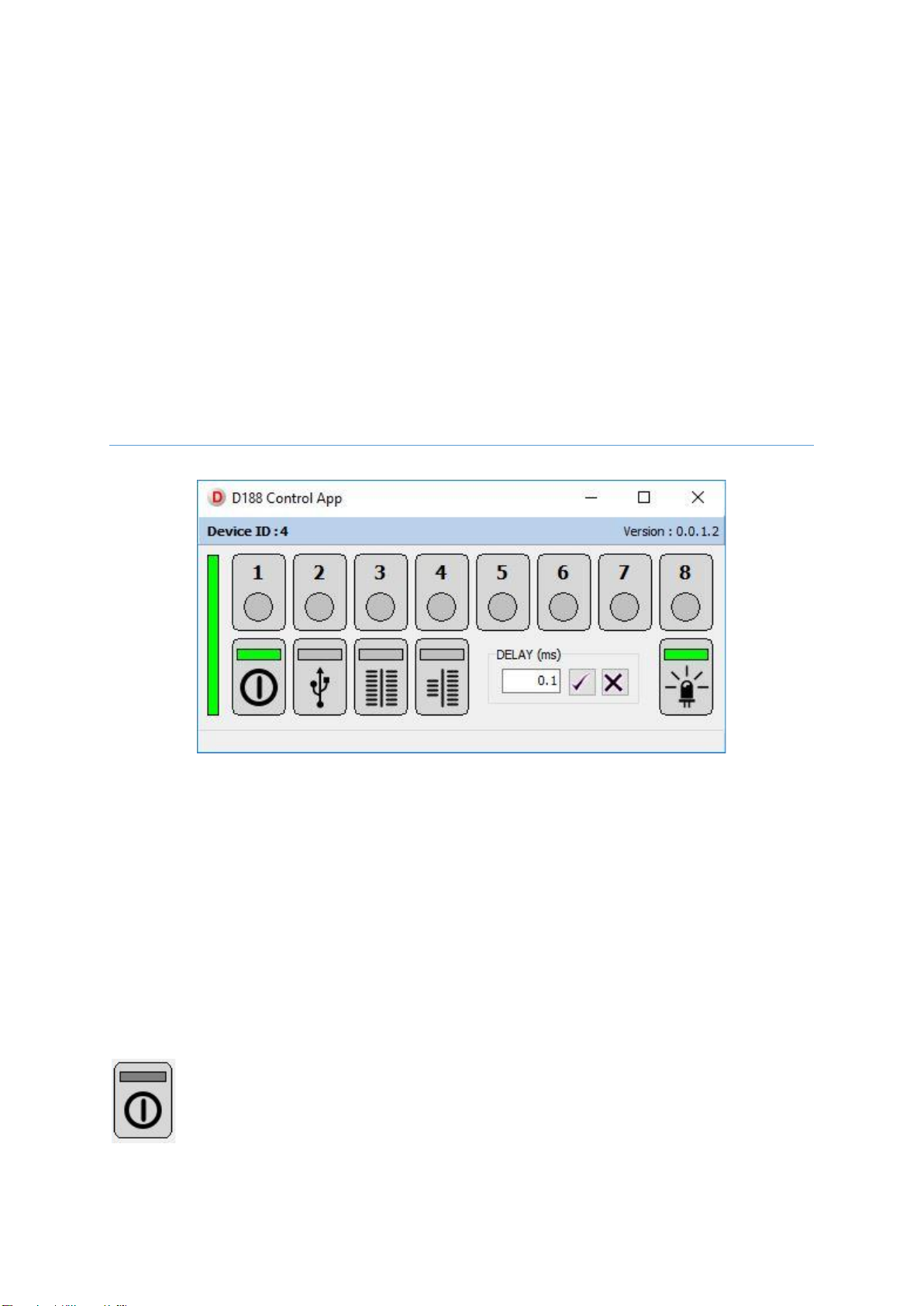
The D188 Control App Software is a virtual front panel for the D188 and allows the operator to manually
switch channels using a left mouse click or keyboard number keys. The software also controls the
operating modes of the D188, whether the LEDs associated with an active channel are illuminated and
the Delay/De-bounce setting.
If multiple D188’s are connected to the host PC, a narrow, vertical green bar moves between respective
D188 panels to show which D188 is being managed (by the number keys) at a particular time.
The D188 has three modes of operation and a standby setting. Modes are selected via a left mouse click
on the mode button of choice. A green bar will highlight the active mode. Additional features and modes
of operation are discussed in greater detail below.
Standby
When the D188 Control Software is first run, with a D188 connected to the PC via the USB
cable, the software indicates the presence of a D188 by displaying the device ID (serial
number) near the top left of the window and adding a green highlight to the Standby button
icon, confirming the D188 is in standby. The D188 will not allow any stimuli to pass through it
until one of the other operating modes below is selected.
Digitimer Ltd –D188 Operator’s Manual Version 1.2
13
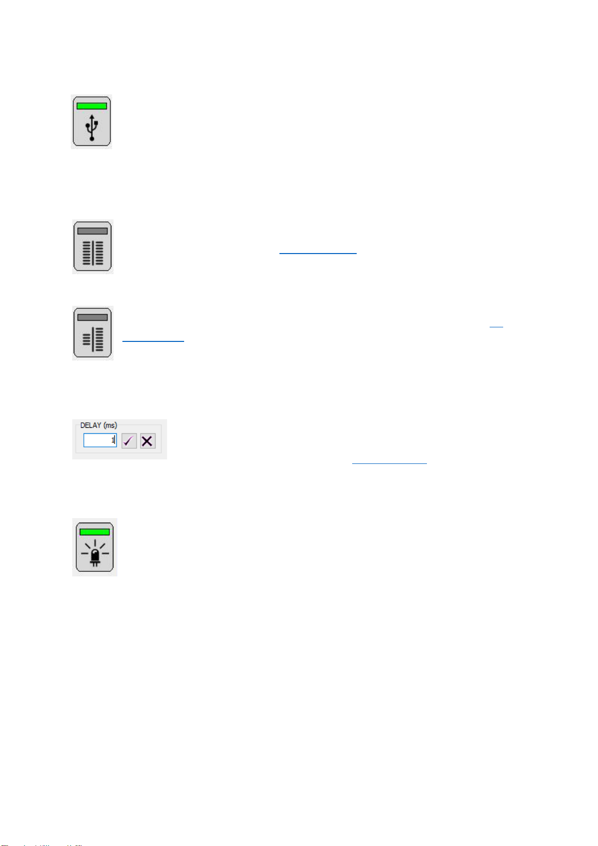
USB (Manual) Control Mode
The simplest control method is to use the USB connection to a host PC and the D188 Control
Software to manually select which channel (electrode pair) is active. To use this mode, the
operator needs to left mouse click on the button with the USB symbol to activate that mode,
moving the green highlight to this button. It is then possible to activate individual channels by
left clicking on each numbered button or using the 1 to 8 keys on the keyboard. The active
channel is indicated by a green circular highlight within the software and a front panel LED on the D188
itself.
1:1 Digital Control Mode
If the operator wishes to control the D188 using digital commands from a data acquisition
board or other device, the D188 has the option to be controlled by 8 TTL compatible (5V)
digital outputs in a 1:1 manner. See 1:1 Digital Control for more detail.
4:8 Digital Control Mode
If eight digital outputs are not available, the operator can choose to use four digital outputs,
defining a 4-bit binary string that the D188 receives through pins 1 –4 (D0 –D3). See 4:8
Digital Control for more detail.
Delay/De-bounce Setting
The Delay/De-bounce setting allows the operator to introduce an adjustable
delay in switching which can be as long as 1000 milliseconds. This ensures that
the voltage at any of the digital inputs has stabilised before the D188 makes
changes to the active electrode pair. See Delay/De-bounce for more detail.
LED Control
In some applications it is important that the operator or subject of stimulation is unaware
which channel is active. The D188 Control Software has a button that “cloaks” the unit,
allowing the LED indicators of active channels to be toggled on or off. When the LED
indicators are active, the LED Control button on the software window has a green highlight.
Persistent Storage of Settings
Note that operating modes and other options are persistent when the D188 is powered off and back on.
Any channels left active (on) in USB (Manual) mode are deactivated when power is removed. This
reduces the risk of unintentional stimulation.

Digitimer Ltd –D188 Operator’s Manual Version 1.2
14

Digitimer Ltd –D188 Operator’s Manual Version 1.2
15
Section 4
System Operation
Introduction
Once the operator is familiar with the D188 hardware and understands how the control software is
operated, the next step is connection of the D188 to the source of stimulation, the stimulation electrodes
and the digital trigger source. A schematic of a typical setup is given below.
The diagram above illustrates how a single PC and compatible DAQ hardware/software can be used to
control the stimulation parameters of a Digitimer stimulator and direct electrical stimuli to one of up to
eight pairs of electrodes, one pair at a time.

Digitimer Ltd –D188 Operator’s Manual Version 1.2
16
Connecting the D188 to an Electrical Stimulator
The D188 is limited to a maximum input voltage of 400V and a maximum current of 1A. It should not
be used with stimulators delivering higher levels than this. The D188 is fitted with a pair of 1.5mm
touch proof DIN 42802 sockets, labelled “COM” which are used to connect the stimulation source to the
D188.
Connecting to a Digitimer DS5, DS7A, DS7AH, DS7R or DS8R Stimulator
D188-09 (2m long) or D188-10 (50cm long) cables are required to attach the D188 input to our popular
D185-HB4 Output Extension Cables.
If a D185-HB4 cable is not used, we offer the D188-12, which is a 50cm pair of cables with 4mm touch-
proof connectors at the stimulator end and 1.5mm touch-proof female connectors at the D188 end.
Connecting to a Digitimer DS2A, DS3 or DS4 Stimulator
As our non-human research stimulators are fitted with 2mm touch-proof sockets, so we offer the 50cm
long D188-11 cables to connect from this 2mm output to the 1.5mm input of the D188.
Connecting to other Stimulators
If the stimulator to be used has an alternative type of output socket, the operator can remove plugs from
one end of the cables above and re-solder with an alternative which is compatible with the stimulator.
Digitimer supplies some plugs, but these are usually of a type compatible with our own clinical and
research stimulators. Please contact us for details.
Connecting the D188 to Stimulating Electrodes
The D188 output connectors are also 1.5mm touch proof DIN 42802 sockets, which are compatible with
many of the electrodes Digitimer offers for human electrical stimulation, including bar electrodes and

Digitimer Ltd –D188 Operator’s Manual Version 1.2
17
digital ring electrodes. The operator has the option of connecting as many pairs of electrodes as needed,
up to a maximum of eight.
If the electrode lead wires are too short, we offer pairs of output extension cables to increase the
distance between the D188 front panel and the subject. These are available in 1m long (D188-13) or 2m
long (D188-14) pairs.
Using Multiple D188’s with a Single Stimulus Source
In order to use more than one D188 and a single stimulator, it will be necessary for the user to connect
the stimulus source, in parallel, to the COM inputs of each D188. In this case, our D185-HB1 output
adaptor cable would be a suitable alternative to our D185-HB4. Alternatively, the stimulus source can be
connected to a single D188 and one output channel of that unit used to pass the stimulus to a second
D188. In this way, multiple D188’s can be “daisy chained” to one stimulator.
Using Manual Control
Manual control allows the operator to switch channels under mouse or keyboard control and is the best
method of control when specifically timed digital control is not required. We recommend that there is a
period of familiarisation, using the D188 in manual mode before any digital control protocols are
commenced. This allows the operator to test and optimize the physical connections between stimulus
source, computer, the D188 and the subject whilst also ensuring that the stimulator settings and
electrodes are appropriate for the chosen application.
Using External Digital Control
Due to the nature of the device, digital control will require the D188 to be interfaced with other
hardware which Digitimer may not supply or support. We therefore urge all users to take care when
programming automated electrode switching processes and stimulus delivery protocols, to ensure that
unexpected stimulation patterns are not delivered. All switching control protocols should be thoroughly
tested before any electrical stimulation is undertaken.
1:1 Digital Control
If the operator wishes to control the D188 using digital commands from a data acquisition board or other
device, the D188 has the option to be controlled by 8 TTL compatible (5V) digital outputs in a 1:1 manner.
The D188 is supplied with a communication cable which connects to the rear of the D188 via the 15-way
“D” connector input. The other end has tinned wires that can be soldered to a specific type of connector,
wired into a break-out box or used with screw terminals on a data acquisition interface. In this operating
mode, if Pin 1 (D0) is held TTL high, Channel 1 is active, if Pin 2 (D1) is held TTL high, Channel 2 is active
etc.
If more than one pin is set to TTL high, all outputs will be disabled, to prevent stimulation through
multiple channels.

Digitimer Ltd –D188 Operator’s Manual Version 1.2
18
4:8 Digital Control
If eight digital outputs are not available, the operator can choose to use four digital outputs, defining a 4-
bit binary string that the D188 receives through pins 1 –4 (D0 –D3). As with 1:1 mode, channels remain
active while the appropriate inputs are held TTL high.
Example Digital Input Configurations:
Channel 2 Active
Channel 4 Active
Channel 5 Active
Channel 8 Active
Pin 1 = 0 (TTL low)
Pin 1 = 0 (TTL low)
Pin 1 = 1 (TTL high)
Pin 1 = 0 (TTL low)
Pin 2 = 1 (TTL high)
Pin 2 = 0 (TTL low)
Pin 2 = 0 (TTL low)
Pin 2 = 0 (TTL low)
Pin 3 = 0 (TTL low)
Pin 3 = 1 (TTL high)
Pin 3 = 1 (TTL high)
Pin 3 = 0 (TTL low)
Pin 4 = 0 (TTL low)
Pin 4 = 0 (TTL low)
Pin 4 = 0 (TTL low)
Pin 4 = 1 (TTL high)
Delay/De-bounce
The Delay/De-bounce setting allows the operator to introduce an adjustable delay in switching which can
be as long as 1000 milliseconds. This ensures that the voltage at any of the digital inputs has stabilised
before the D188 makes changes to the active electrode pair. This may be of use if mechanical switches
are used to control the D188, as “switch bounce” could be interpreted by the D188 as multiple rapid
changes between TTL low and high, rather than a single state change.
Minimum Switching Times & Stimulus Pulse Duration
It is important to appreciate that the electrode switching process is not instantaneous. It takes several
hundred microseconds for the D188 to switch channels in response to a change in the TTL state of the
digital inputs. We recommend that stimulus delivery and digital switching protocols are devised which
allow for a 1ms pause in stimulation following a digital input state change. If this pause is not adhered to,
stimulation may occur in multiple channels during the 1ms transition period.
The recommended 1ms pause, following changes in the digital inputs, is indicated by the red blocks in the
illustration above.

Digitimer Ltd –D188 Operator’s Manual Version 1.2
19
It is also important that the duration of an electrical stimulus is considered when programming a
switching protocol. We recommend that any stimulus delivery events are bracketed by longer periods of
D188 channel activation to ensure that the stimulation pulse has ceased and fully dissipated before the
channel being stimulated through is changed.
Digital Control Voltage Requirements
In the 1:1 mode the D188 requires +4V (@ 50µA), but when operated in 4:8 control mode, i.e. specifying
the active channel using a 4-bit binary string rather than using 8 digital inputs, then the required voltage
is lower and a device generating +3.3V would be adequate.
Using the API for Third Party Software Control
The D188 control software includes an API. While we recommend using digital control to switch channels
for applications that require precise timing, it is possible to use third party software to switch channels
via the USB connection.
During installation of the D188 software, the DGD18API.DLL is placed in the Windows System folders
(System32 and SysWOW64).
To assist developers we provide a sample C++ example program within a zip file (D188-VS-
C++Example.zip), located in C:\Users\<username>\Documents\Digitimer Limited
Example Applications
Below we include an example application which illustrates how the D188 has been used. We invite all
D188 users to submit a brief summary of the application and list of hardware and software they are
using, so we can add details to this section.
Application 1: Tactile stimulation of multiple digits (sequentially) across both
hands.
The aim was to develop a diagnostic test for somatosensory cortical reorganisation in patients with
Complex Regional Pain Syndrome. Stimulation was applied no faster than 1Hz, with stimuli either
repeating on the same digit or switching digits in a manner that appears random to the subject, but
follows a pre-programmed sequence.
Hardware
Labjack U3-HV (www.labjack.com) sends instructions to the Digitimer D188 to change channel (digit
stimulated) and to the Digitimer DS7A to stimulate via digital ring electrodes.
Software
Matlab (2015 version, www.mathworks.com) programming creates stimulation sequences and
instructions to the Labjack which time the digit changes and digit stimulations via the D188 and DS7A
respectively. Control of the Labjack requires specific drivers and commands supplied by Labjack for use in
Matlab.

Digitimer Ltd –D188 Operator’s Manual Version 1.2
20
Digitimer Limited
37 Hydeway
Welwyn Garden City
Hertfordshire
AL7 3BE
UK
Tel: +44 (0)1707 328347
Fax: +44 (0)1707 373153
E-mail:
Website: www.digitimer.com
File Reference: N:\Docs\Company\Manuals\D188\D188_Manual_v1.2.docx
Last updated: 30/09/21
Table of contents
Other Digitimer Laboratory Equipment manuals

Popular Laboratory Equipment manuals by other brands

Witeg
Witeg Wisd CF-10 operating manual

National Instruments
National Instruments NI VB-8012 SAFETY, ENVIRONMENTAL, AND REGULATORY INFORMATION

SDL Atlas
SDL Atlas QuickWash Plus instruction manual

taurus Healthcare
taurus Healthcare Everyday Purity manual

Powerfiller
Powerfiller POWERFILLER 4 user manual

Thermo Scientific
Thermo Scientific DensityPRO-T installation guide


