AC/DC
Adapter
Connection
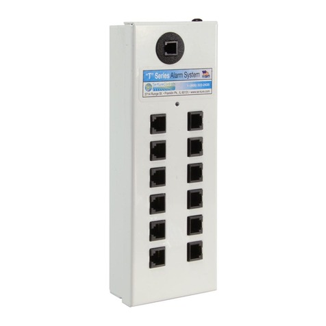
Splitter Box
Connection
(Coupler)
Splitter Box
Connection
(Coupler)
Sensor Ports w/Lights
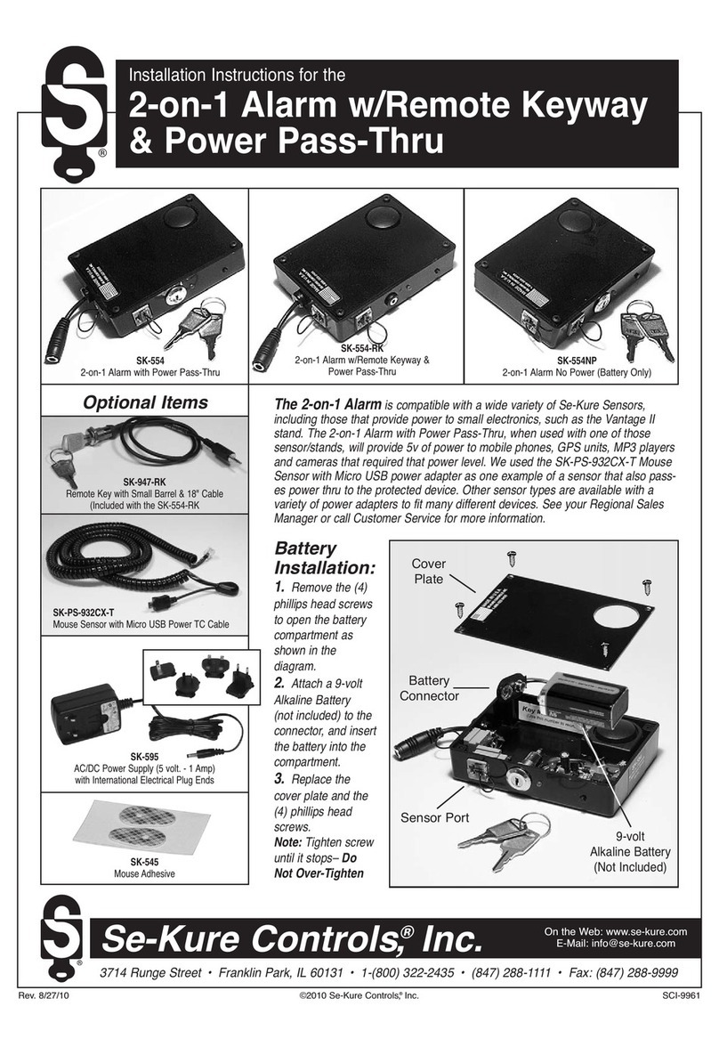
Power
Test
Light
Circuit Test Light
Alarm Box Screws
Key Switch
SK-103LE
Rectangular
Adhesive Pad
SK-905
SK-109
“Shunt Plug”
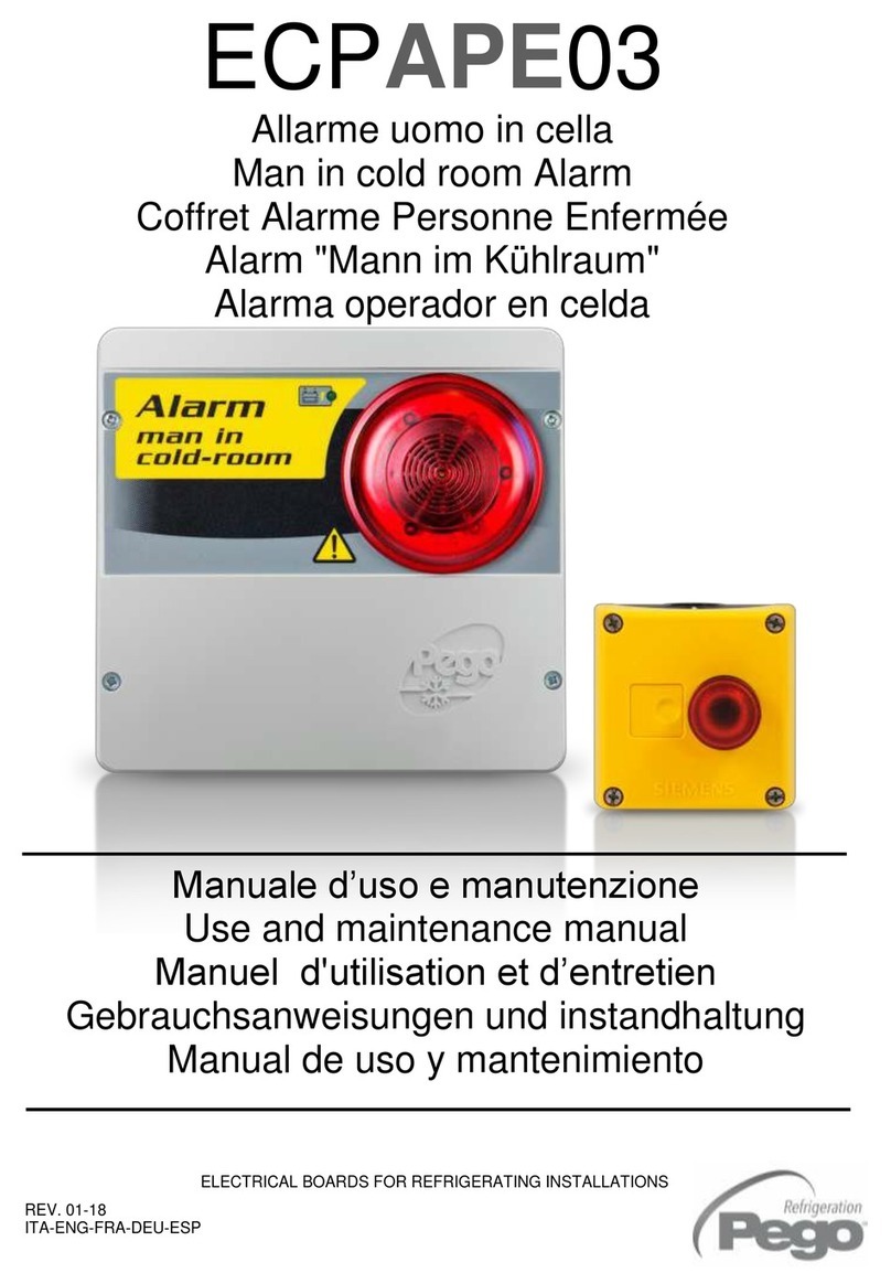
“LE” Alarm Box
Battery Installation:
1. Insert the key into
the “LE” Alarm
Box and turn it
“Clockwise” to the
“OFF” position.
Note: The key cannot be removed when is is in the “OFF” position.
2. With a Standard Blade Screw Driver, remove the (4) four screws around the
base of the “LE” Alarm Module. Make sure the key is in the “OFF” position,
and lift off the cover.
3. Install (2) two new 9-volt Alkaline, (such as Duracell)
batteries, (not included) inside the “LE” Alarm Box
by first positioning them on the connectors attached
to the circuit board and then pushing them firmly
into place, as shown in Fig. 1 to the right). The
Power Test Light (yellow) should flash indicating
that the power is on. This light will flash every 15
seconds indicating that the batteries are in good
working condition and the power is supplied to the unit.
Note: When the yellow light flashes and simultaneously the horn “chirps”
twice the batteries need to be replaced immediately.
4. Replace the cover onto the “LE” Alarm Module and Re-Install the (4) four
screws around the base.
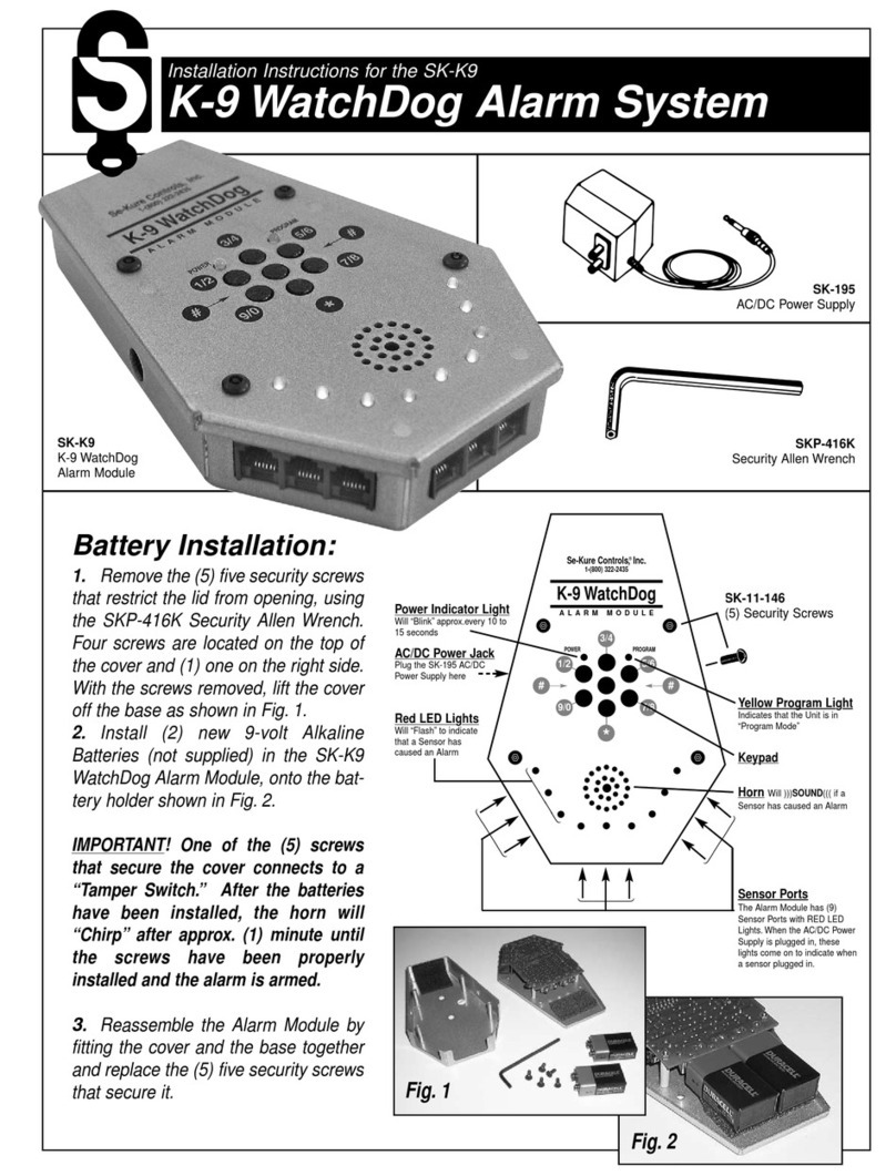
5. Connect the (SK-195) AC/DC Power Supply to the jack on the rear of the
“LE” Alarm Module. Be sure to insert the plug fully into the jack! Plug the
other end of the AC/DC Power Supply into a standard 110-115v AC wall
outlet.
Note: If NO BATTERIES ARE INSTALLED, the yellow light will flash and
simultaneously the alarm horn will “chirp” twice until the batteries are
installed or the power is disconnected.
Splitter Box & Strip Alarm Connections:
6. Plug a Splitter Box or Strip Alarm into the Splitter Box Connector located at
the end of the Alarm Box cable, (see the illustration at the top of the page).
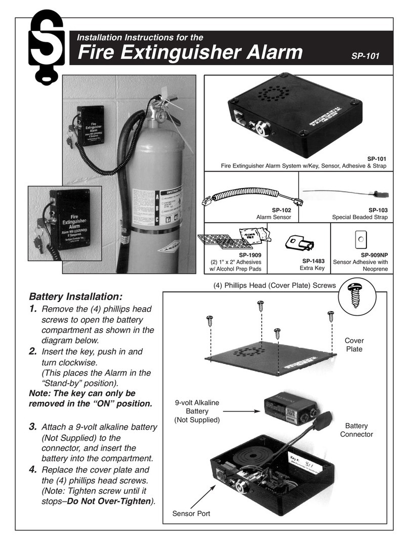
7. Remove the “Shunt Plug” from the Coupler Port of the first Splitter or Strip,
and connect the 2nd Splitter or Strip to the Coupler Port of the 1st.
Fig. 1
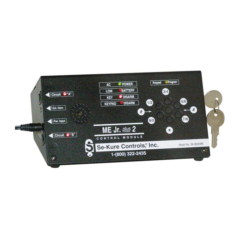
Fig. 2
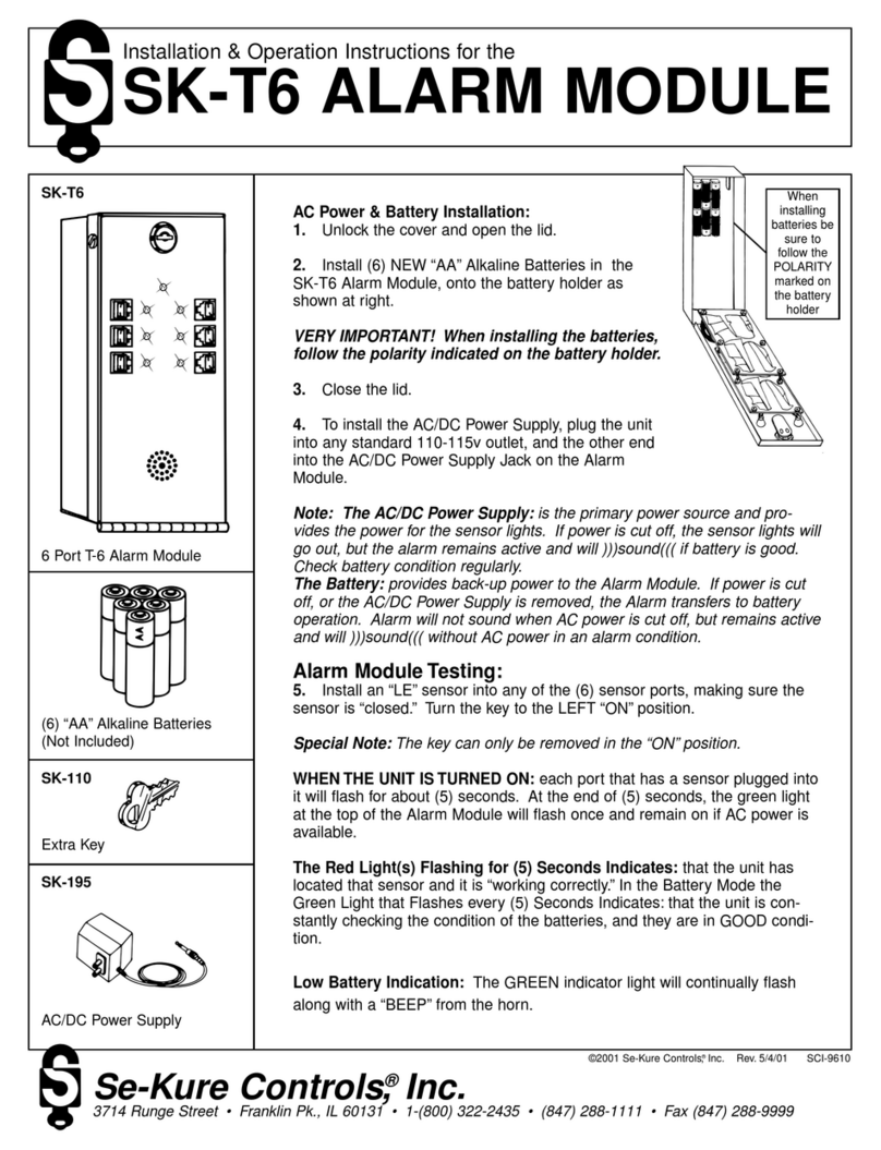
Fig. 3
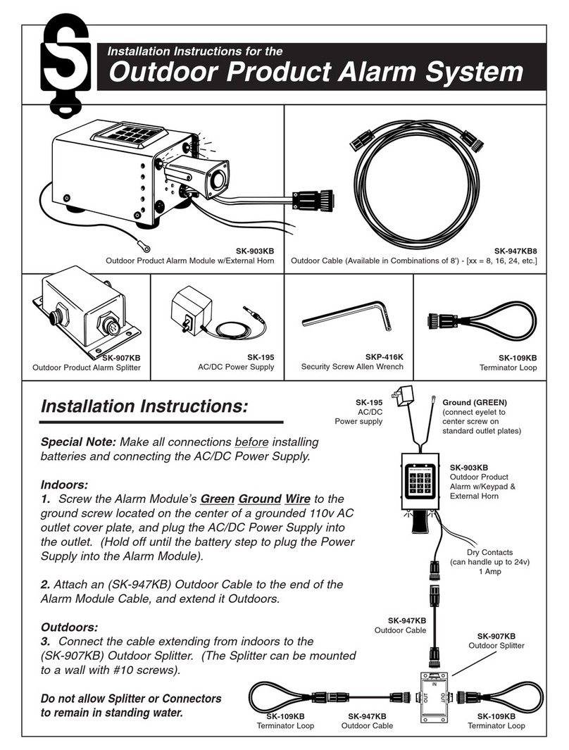
Fig. 4
Sensor Connections: – To Splitter Boxes & Strip Alarms
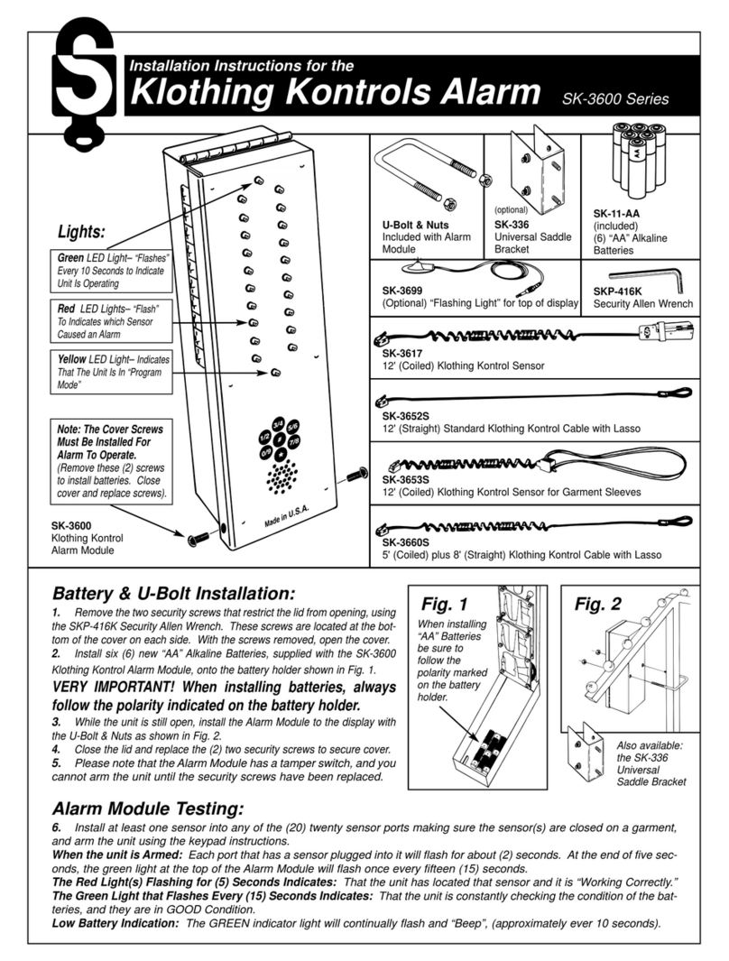
8. Remove and SAVE the “Shunt Plug” from a Sensor Port, (see Fig. 2 above).
Insert a sensor’s modular plug into that port. Repeat this procedure until
all sensors have been plugged in. All ports should have either a “Shunt
Plug” or a Sensor with a lit GREEN light plugged into it.
Sensor Connections: – To Product (SK-904 Series Sensors)
9. Choose a small flat area on the back of the product where the sensor is to
be applied.
VERY IMPORTANT!
NOTE: Clean the area on the product and the sensor with
Alcohol Prep Pads. Wipe these surfaces DRY with a clean
paper towel. If the paper towel shows dirt, REPEAT THIS
CLEANING STEP until the surfaces are CLEAN & DRY!
10. Remove an SK-905 (1" x 2") Rectangular Adhesive Pad from its backing
sheet. Apply the adhesive pad to the bottom of the sensor, making sure
that the center hole of the adhesive lines up with the plunger on the bottom
of the sensor. (See Fig. 3 below).
11. Remove the backing sheet from the other side of the adhesive pad and
position the Rectangular Sensor over the flat area of the product previously
cleaned. Press the sensor firmly into place to insure a proper bond, (as
shown in Fig. 4 below). The light on the sensor will change to RED when
the sensor is applied correctly to the product
Clean &
Wipe Dry
Coupler Port
(for Additional Splitters & Strips Only)
DO NOT USE AS A SENSOR PORT
Remove
Adhesive
Backing
