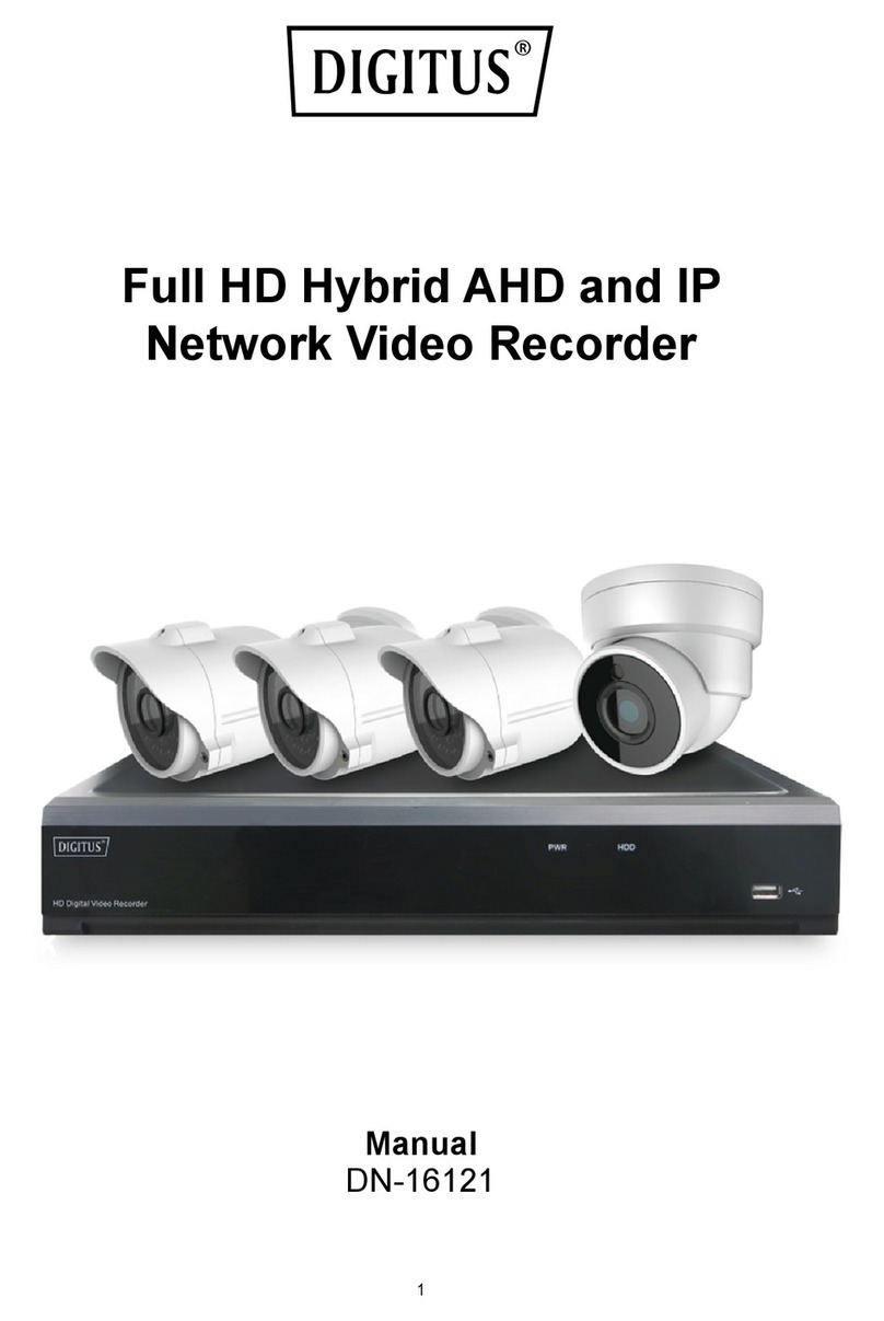
Digitus DN-16150 User manual

1
NETWORK VIDEO RECORDER
DIGITUS®PLUG&VIEW NVR
Quick Installation Guide
DN-16150

1.1
NVR
Item
1
2
3
1.2
NVR
Item
1
2
3
4
5
6
Front
P
Front Pa
n
Key Na
m
Indicato
r
Power
Indicator
HDD Ind
i
USB
Rear P
a
Rear Pan
e
Physical P
o
Power Por
t
USB Port
HDMI Port
VGA Port
A
UDIO O
U
LAN Port
P
anel
n
el
m
e or
r
R
e
P
i
cato
r
H
a
nel
e
l
o
rt C
o
t
St
a
C
o
H
D
C
o
U
TPUT
Au
N
e
e
mark
P
WR
If
n
o
H
DD
If
t
wr
di
s
U
S
o
nnection
M
a
rt-up and s
h
o
nnect USB
d
D
MI high de
f
o
nnect to V
G
u
dio si
g
nal o
u
e
twork input
2
the “Green
o
rmally.
t
he “Red” in
d
r
itten to. If t
h
s
k is abnorm
S
B port for U
M
ethod
h
utdown wit
h
d
evices, su
c
f
inition port
G
A monitor, s
u
tput, RCA i
n
interface of
t
Function
” indicator
d
icator flash
e
h
e indicator
al, unformat
t
SB mouse
o
h
DC12V po
w
c
h as USB m
uch as PC
m
n
terface
t
he router or
& Descrip
t
is on, NV
R
e
s, the hard
d
is always o
n
t
ed or has n
o
o
r USB pen
d
w
er
ouse and U
S
m
onitor
Ethernet s
w
t
ion
R
is gettin
g
d
rive is bein
g
n
, it means
t
o
recording
f
d
rive
S
B flash dis
k
w
itch
g
power
g
read or
t
he hard
f
iles.
k

3
Chapter 2 NVR Connection
2.1 HDD Installation
Caution: Please do not take out hard drive when NVR is running!
HDD Installation:
(1) Cut power first, then remove the screws on both sides and rear panel and open the NVR
upper cover.
(2) 1. Insert 4 hard drive screws into the bottom of the hard drive and tighten them 1/2 of the
way.
2. Place the hard drive in the screw slots with the power and data connectors facing left (if
looking at the NVR from the front), and slide the hard drive into place.
3. Tighten the hard drive screws to secure the hard drive in place.
(3) Connect the HDD data cable and power cable to the main board. Install the HDD and fix it
on the bracket; then connect the HDD power cable and data cable.
2.2 Setup
After hard disk installation, connect the NVR to the router or Ethernet switch using an Ethernet
cable to the LAN port on the NVR. Then connect either a VGA or HDMI monitor to the NVR as
local display. Also connect USB mouse to the USB port on the NVR to setup configuration.
Then power on the NVR with the DC12V power adapter.
In parallel, install up to 4 DIGITUS Plug & View cameras via a router or Ethernet switch on the
same network as the NVR.

4
Chapter 3 NVR Boot Up
3.1 System Initialization
On the local display with the VGA or HDMI monitor, after connecting the power cable of the
NVR to a wall outlet and pressing the power button, you will see on screen that the NVR
system is initializing, as shown below.
3.2 Setup Wizard
After NVR start-up is completed, enter “admin” for both login and password to login. The
“Setup Wizard” will be displayed. Follow the “Setup Wizard” to guide you through the first time
installation.
Local Display with
HDMI or VGA
monitor
DC12V input
power supply
USB mouse for local
control and configuration

5
Wizard setting menu includes: Homepage, Network Setup, IPC Setup, Record Schedule and
Hard Disk Maintenance.
1. Homepage and Network Setup. On the Network Setup page, keep the default “DHCP”
setting as the NVR will be assigned with an IP address automatically when it is connected
to the router or access point.
2. IPC Setup: On this page, you add and delete IP cameras. It automatically searches all the
DIGITUS Plug & View IP cameras installed under the same network as the NVR. Then you
select the desired cameras for recording to NVR by enabling the channels.
Record Schedule: On this page, you set recording time and scheduled recording of the
NVR.
3. HDD: It supports HDD formatting and overwriting setting.

6
Chapter 4 NVR Menu
4.1 Main Menu
In LIVE mode, click or press the [Menu]
button on the remote control, or click the
[ ] icon in the toolbar to enter the
main menu for more setting options.
4.2 IP Camera
Go to “Main Menu” →“Parameter” →“Display” →“IP Camera” to enter the menu as shown
below.
Channel: IP camera channel.
Edit: Modify the name and location of
channels, change settings.
State: Display camera online status.
IP Address/Domain: IP address of the
IP camera connected of the channel.
Subnet Mask: IP camera subnet mask.
Port: Connection port number of the
currently set IP camera.
Alias: The name you can give to the
camera.
IP Address/Domain: IP address
should be automatically assigned by
the router.
Subnet Mask: IP camera subnet mask.
Port: The port number is normally
automatically detected and displayed. I
f
it is not displayed, for DIGITUS Plug &
View Revision1 camera, the port
number is 80. For Revision2 camera,
the port number is 1018.
User Name: Enter “admin”.
Password: Enter “admin”.

7
4.3 Live View
Go to “Main Menu” →“Parameter” →“Display” →“Live” to enter the menu as shown below.
Channel: Select channel number.
Show Time: Tick the checkbox to
display the time.
Channel Name: Name marked on IP
camera.
Date Format: Set date format such as
mm/dd/yyyy or yyyy/mm/dd.
Time Format: 12-hour or 24-hour.
OSD Position: Freely set the position
of IP camera name and time.
4.4 Output
Go to “Main Menu” →“Parameter” →“Display” →“Output” to enter the menu as shown below.
Video Output: Live output.
Seq Mode: Set sequence mode.
SEQ Dwell Time: Sequence dwell time
is 5 seconds by default. You may set it
as required.
VGA/HDMI Resolution: VGA output or
HDMI output. Including 1024×768,
1280×1024, 1440×900, 1280×720,
1920×1080, 1680×1050, 1600×1200,
1900×1200, 2560×1440, 3840×2160.
Transparency: Set the transparency o
f
the menu in the range of 0-128.
4.5 Record
Go to “Main Menu” →“Parameter” →“Record” →“Record” to enter the menu as shown below.
Channel: Set the desired channel in the
drop-down menu.
Record: Set up the record status
(Enable/Disable) of each channel.
Stream Mode: Select Mainstream or
Substream.
PreRecord: “Enable” status supports
pre-record for motion detection record o
r
I/O trigger record.

8
4.6 Schedule
Go to “Main Menu” →“Parameter” →“Record” →“Schedule” to enter the Schedule interface
and set the recording schedule of the NVR.
Select the channel and the date to be set.
One week’s schedule can be set.
The recording schedule of the current
channel can be copied to any other channel
or all channels.
Note:
1. In the Record menu and Record Search
menu, No Color stands for no record.
2. “Green” stands for normal record and
“yellow” stands for motion record.
3. “Red” stands for alarm record.
4.7 Mainstream/Substream
Go to “Main Menu” →“Parameter” →“Record” →“Mainstream/Substream” to enter the menu
as shown below.
Mainstream and substream are the two video
streams of the IPC. Mainstream is mostly
used for recording and the substream is
mostly used for remote network monitoring.
Channel: Select a channel.
Resolution: Set camera resolution.
FPS: Min 1 and max 30.
V
ideo Code Type: H.264.
Bitrate: Set IPC bitrate.

9
4.8 Record Search
Go to “Main Menu” →“Record Search” →“Record Search” to enter the menu as shown below.
Channel: Select the channel you want
to search.
Type: There are two options besides
All: Normal and Alarm.
Start Time/End Time: Select the
specific period of time. The default
setting is from 0:00 to 24:00.
Playback Channel: Click a date and
select the corresponding channel in
Playback Channel.
Playback: Select the desired year and
month and click “Search”. If there are
any records, a green corner mark
which shows the recording at the
specified date will appear in the bottom
right corner of the date sheet. Select
the date checkbox and select the
playback channel; then click Playbac
k
to enter the menu.
Playback menu: You can use the
Playback control bar to operate Fast
Forward (X2, X4, X8 and X16), Rewind
(X2, X4, X8 and X16), Slow play (1/2,
1/4 and 1/8 speed), Play,
Pause/Frame. Click or drag the volume
control bar to adjust the volume. When
playback ends, the NVR will remain in
the playback menu.
4.9 Play Backup Files
1. Copy backup files to the computer.
2. Open playback player and click “+” or “ ”. For example, if you want to select
*.264, add backup file and select a file to play

:
P
:
P
:
S
t
:
N
:
P
:
S
:
F
a
:
O
:
F
u
:
N
:
Al
:
O
:
S
:
A
:
D
:
D
:
E
x
:
A
langu
a
lay: Click to
ause: Click
t
op: Click t
o
ext: Click t
o
revious: Cli
c
low Play: cl
i
a
st Play: cli
c
O
pen file.
u
ll screen d
i
ever on top
.
l
ways on to
p
O
n top durin
g
creenshot:
S
A
dd folder o
elete file in
t
elete all file
s
x
pand/pack
A
dvanced c
o
a
ge of the p
l
play file.
to pause.
o
stop playb
a
o
play next fi
c
k to play p
r
i
ck to play a
c
k to play a
t
i
spla
y
.
.
p
.
g
playing.
S
ave path: i
:
A
djust vo
r file.
t
he list.
s
in the list.
up the list.
o
nfiguration:
l
ayer.
a
ck.
le.
r
evious file.
t 1/2, 1/4, 1
/
t
2×, 4×, 8×,
nstallation
d
lume.
Set the sa
v
10
/
8, 1/16 spe
16× speed
.
d
irector
y
\Vid
v
e path for
t
ed.
.
eo Client\C
a
t
he capture
d
a
pture.
d
pictures
a
a
nd set the
d
d
isplay

11
5.0 Device
Go to “Main Menu” →“Device” →“HDD” to enter the menu as shown below.
When NVR is connected to a HDD, the
system will automatically detect if HDD is
normal or not; if HDD needs to be
formatted, the status will be shown as
“Not formatted”. Select the HDD and
format the HDD. If the system detects
HDD is in normal state, the HDD status
will be shown as “Normal”.
No.: Number of HDD connected.
State: It shows the current status of the
HDD. Available only when HDD is
“Normal”.
Free/Total Space: Remaining or total
space of HDD.
Free Time: Remaining time for HDD
recording according to currently set
“Resolution”, “Encoding Rate” and
“Frame Rate” of image.
Overwrite: When set to AUTO, the NVR
will overwrite the oldest files on the hard
drive if hard drive space is full. When set
to DISABLE, the NVR will stop recording
if the hard drive space is full. Overwrite
time: 1 day, 3 days, 7 days, 14 days, 30
days and 90 days. It means the longest
storage time of records on the HDD. I
f
the time expires, the records will be
deleted. For example, if the time is set to
3 hours and the data on the HDD include
12, 13, 14, 15, 16, 17, 18, 19 and 20
o’clock, then data 18, 19 and 20 will be
saved and data 12, 13, 14, 15, 16 and 17
will be deleted.
Format HDD: Format HDD for first use.
Note: Recording can only be performed when HDD is in “Normal” state.

12
5.1 Advanced
Maintain
Go to “Main Menu” →“Advanced” →“Maintain” to enter the menu as shown below.
Auto Reboot: Enable the auto
maintenance function to reboot system
regularly at every day/week/month.
When Auto Reboot is enabled, the NVR
should be in the main menu and no use
r
operation.
Upgrade: Decompress update file
package and copy the upgrade file folde
r
named “nvrupgrade” (the upgrade
program is inside) to the root directory o
f
a USB stick; insert the USB stick in the
USB port of the NVR; click <Upgrade>.
Load Default: If [Load Default] is
selected, you can initialize the system to
the factory default setting. Click “Load
Default” and select items to be restored.
Load Settings: Load parameters from
the removable storage device to the
NVR.
Save Settings: Save the set parameters
of user’s NVR to the removable storage
device.
5.2 Shutdown
Go to “Main Menu” →“Shutdown” to enter the menu as below picture.
Shutdown function requires you to login by entering user name and password to shut down or
reboot the system.

13
6.0 Web UI Access via Browser
Open your web browser (Internet Explorer, Firefox or Chrome) and enter the IP address of the
NVR, such as: http://192.168.1.168. If your computer is connected to the Internet it will
download and install “ActiveX” plug-in automatically. If your computer system is Windows Vista
or Windows 7, you may need to setup the user authority for remote control, or you may be
unable to backup or record. You can also find the IP address of the NVR on the local display of
your VGA or HDMI monitor under “Network” settings.
After ActiveX controls installation, enter “admin” as your user name and “admin” as your
password to login. Select Main stream or Sub stream (in general, select Main stream for
intranet and Sub stream for Internet), then select the language.
6.1 Live Interface

14
7.0 Mobile Access:
Please download “Digitus Recorder” APP from the APP store or Google Play to see live-view
and playback from smart phones.
Note: In case of incorrect installation and improper use in a residential area, the interference to radio
devices and other electronic devices could be caused. It is recommended to use the device where
applicable with shielded cables (also shielded with networking products of cable Category 5e and
higher). The device was tested to comply with the limits for Computer and IT accessories of Class A
according to the requirements of EN 55022.
Warning: This product complies with the test class A - It may be used in the living area but could cause
radio interference; in this case, it may be demanded by the operator to take appropriate corrective
action at his/her own expense. Declaration of Conformity: The device meets the EMC requirements
according to EN 55022 class A and EN 55024 for ITE category with external or built-in power supply to
meet the requirements of EN 61000-3-2 and EN 61000-3-3 according to the EMC Directive
2004/108/EC. The declaration of Conformity can be requested by post at the following manufacturer
address.
www.assmann.com
ASSMANN Electronic GmbH
Auf dem Schüffel 3
58513 Lüdenscheid
Germany
Other manuals for DN-16150
1
Table of contents
Other Digitus Network Hardware manuals
Digitus
Digitus DN-16114 User manual

Digitus
Digitus DN-7071 User manual

Digitus
Digitus DN-95131 User manual

Digitus
Digitus DN-15022 User manual

Digitus
Digitus DN-15028 User manual

Digitus
Digitus Unique Series User manual

Digitus
Digitus DN-15024 User manual

Digitus
Digitus DN-91624S-SL-EA User manual
Digitus
Digitus DS-55317 User manual

Digitus
Digitus DN-16121 User manual
Popular Network Hardware manuals by other brands

Juniper
Juniper CSE2000 Hardware installation guide

TRENDnet
TRENDnet TPE-113GI Quick installation guide

Texas Instruments
Texas Instruments LMK05318B EVM manual

Interlogix
Interlogix TruVision NVR 21 user manual

Mobatime
Mobatime BU 190 S 48 Installation and operating

Fujitsu
Fujitsu MB88121 SERIES user guide