Dillon Precision Products Square Deal B User manual

Square Deal “B” Reloading System Assembly
and
User Instructions
Dillon Precision, Inc.
Copyright © 2020 by Dillon Precision, Inc.--All rights reserved. This publication is for personal use only. No part of this publication may be reproduced, distributed, or
transmitted in any form or by any means, including photocopying, recording, or other electronic or mechanical methods, for commercial use without the prior written permission of
Dillon Precision.
Square Deal™ and Dillon Square Deal B Reloading System™ are trademarks of Dillon Precision Inc.
Rev. 0 January 2021

2
TABLE OF CONTENTS
1. THE BASIC RISK OF RELOADING---Page 4
2. MANDATORY SQUARE DEAL “B” USER SAFETY MINIMUM REQUIREMENTS—Page 4
3. SQUARE DEAL LIMITED LIFETIME WARRANTY—Page 5
4. SQUARE DEAL SHIPPING CONTENTS—Page 5-6
5. SQUARE DEAL ASSEMBLY GUIDE—Pages 6-11
6. OPTIONAL EQUIPMENT FOR THE SQUARE DEAL—Page 12
7. THE DILLON SQUARE DEAL RELOADING STATIONS AND CONFIGURATIONS—Pages 13-15
8. SETUP PROCEDURES FOR THE SQUARE DEAL—Pages 16-30
8.1. Description of Square Deal Die Assemblies
8.2. Square Deal Friction Plate
8.3. Station 1--Sizing and Depriming
8.4. Station 2a--Primer Feeding and Seating
8.5. Station 2b—Powder Measure Setup and Case Mouth Belling
8.6. Station 3--Bullet Seating
8.7. Station 4--Bullet Crimping
9. CONVERSION LIST AND REPLACEMENT PROCEDURES—Pages 30-39
9.1. Caliber Conversion List
9.2. Shellplate Caliber and Primer Size Conversion
9.3. Die Caliber Conversion
9.4. Powder Measure Bar Conversion
9.5. Depriming Pin Replacement
9.6. Primer Early Warning Battery Replacement
10. ADJUSTMENT AND REPLACEMENT PROCEDURES—Pagers 40-43
10.1. Shellplate Indexing Adjustment
10.2. Adjusting Primer Feeding/Alignment
11. TROUBLESHOOTING THE SQUARE-DEAL—Pages 44-46
12. CLEANING AND LUBRICATING THE SQUARE DEAL—Pages 47-49
13. SUB-ASSEMBLIES AND PARTS IDENTIFIER—Pages 50-56
13.1. Main Assembly
13.2. Frame and Lower Assembly
13.3. Automatic Primer Assembly
13.4. Primer Early Warning Assembly
13.5. Primer Slide Assemblies
13.6. Primer Early Warning System
13.7. Automatic Powder System
14. RELOADING BASICS--Pages 57-59
15. NOTES--Page 60

3
DILLON PRECISION DISCLAIMER, EXPLANATION OF SAFETY WARNINGS, DILLON CONTACT INFORMATION
DISCLAIMER
The material in this manual is for informational purposes only. The products it describes are subject to change without prior
notice. Dillon Precision Inc. makes no representations or warranties with respect to this manual.
Dillon Precision Inc. shall not be liable for any damages, losses, costs or expenses, direct, indirect or incidental, consequential
or special, arising out of, or related to the use of or the inability to use the products described herein.Read this manual
before using this product. Failure to follow the instructions and safety precautions in this manual can result in serious injury
or death. Keep this manual in a safe location for future reference.
EXPLANATION OF SAFETY WARNINGS
DANGER!
Danger! indicates a hazard with a high level of risk that if not avoided, will result in death or serious injury.
WARNING!
Warning! indicates a hazard with a medium level of risk that if not avoided, could result in death or serious injury.
CAUTION!
Caution! indicates a hazard with a low level of risk that if not avoided, could result in minor or moderate injury.
Dillon Contact Information
Dillon Precision Inc.
8009 E. Dillon’s Way
Scottsdale, AZ 85260
480-948-8009 1-800-223-4570
FAX 480-998-2786
Website: www.dillonprecision.com
E-mail: dillon@dillonprecision.com
Sales, Technical Support and Customer Service
800-223-4570
Document Revisions
Date Version Number Document Changes
1-1-2021 0 Initial Release Updated Manual

4
MANDATORY SAFETY PRECAUTIONS—MUST BE READ
1. The Basic Risk of Reloading, and Overall Square Deal Design Usage Safety:
1. DANGER! The reloading of ammunition and the handling of reloading components used in the reloading process is inherently
dangerous. Accidents and mistakes in loading can and do occur, sometimes with disastrous results resulting in, but not limited
to loss of hearing, vision, limbs or life. These accidents can occur with the novice and experienced reloader.
2. Dillon Precision Inc. has designed the Square Deal “B” with user safety in mind, doing everything Dillon Precision Inc. knows to
make the use of the Square Deal “B” as safe as possible.
2. Mandatory Square Deal User Safety Minimum Requirements:
1. Dillon Precision Inc. cannot guarantee the complete safety of the reloader/user of the Square Deal “B”. To minimize the user’s
risk, use common sense when reloading and follow these basic safety rules at a minimum.
2. KNOWLEDGE: Study and learn the basics, processes and specifications used in the reloading of ammunition from reputable
sources and publications by prominent bullet and powder manufacturers such as Sierra, Hornady, Speer, Western Powders and
Alliant Powders; including reloading manuals such as the Lyman Reloading Manual and the Western Powder Reloading Guide.
3. EYE AND EAR PROTECTION: Never operate the Square Deal without eye and ear protection.
4. PAY ATTENTION: Give your full attention to the reloading process. Do not watch television, the internet or converse with
anyone while loading. It is a full-time operation.
5. INTERRUPTIONS: If you are interrupted in any manner, always inspect the cases at every station and know exactly what has
been done to ensure that proper process steps have or have not been completed.
6. SMOKING/IMPAIRMENT: Do not smoke or allow anyone to smoke in the reloading area. Do not allow open flames. Do not
load if you have been drinking alcohol or are impaired in any way.
7. SAFETY: Do not remove any safety device(s) from the reloader or modify the reloader in any way. Keep components and
ammunition out of the reach of children.
8. LEAD--CAUTION! Almost all bullets have a lead component, which may or may not be exposed. Be sure to have proper
ventilation while handling the lead component (bullet) or when shooting. Lead causes birth defects, reproductive harm and
cancer. Wash your hands thoroughly after handling lead components or shooting.
9. POWDERS--DANGER! There are many kinds of powders (propellants) used in the reloading process and are in general specified
as rifle, pistol or shotgun powders. Powder selection is specific to the bullet caliber, weight and type of bullet being reloaded.
There is no way to overstate the care and selection of a powder to be used in the reloading process. Again, refer to
established bullet and powder manufacturers. Using the wrong powder or amount of powder or mixing powders can result in
serious injury or death. Never mix powders. Always store the powder in its original container. Never have more than one
type of powder in the reloading area at one time—preferably store powders in a separate room. Observe all maximum load
warnings.
10. PRIMERS—DANGER! Primers contain a small amount of a shock-sensitive chemical that explodes when struck by a firing pin
or hammer or accidentally crushed. Never force primers. If they get stuck in the operation of the loader, carefully disassemble
the reloader and gently remove the obstruction. Never attempt to clear primers that are stuck in either the primer pickup tube
or the primer magazine tube. Never, under any circumstance, insert any type of rod into these tubes to attempt to push out
stuck primers—PRIMERS CAN “CHAIN DETONATE.” If a primer(s) gets stuck in the magazine or pickup tubes flood the tube
with penetrating oil/WD-40, throw it away and call Dillon for a free replacement. Never attempt to deprime a cartridge case
with a live primer. Depriming a live primer is one of the most dangerous things you can do in reloading and can cause serious
injury or death. Never attempt to further seat primers on a loaded cartridge. Use only the primer for the specific application
for which you are loading.
11. BLACK POWDER--DANGER! Do not use black powder or black powder substitutes in any Dillon Powder Measure. Doing so can
result in severe injury or death.
12. LOAD AND LOADED LENGTH—WARNING! Use only recommended load specifications from manuals and information supplied
by established, known component manufacturers. Avoid maximum loads listed in loading manuals. Be extremely careful to
avoid a double charge. Dillon has no control over the components and specifications used when reloading with the Dillon
equipment. No responsibility is implied or assumed for results obtained through the use of or inability to use any such
components or reloading specifications.
13. QUALITY CHECKS--At a minimum, perform periodic quality checks every 50-100 reloads-ESPECIALLY the powder charge.
14. PROPERLY LABEL RELOADED AMMUNITION: Label the reloaded cartridge with the overall length, bullet manufacturer, type
and weight-- primer manufacturer and type--powder manufacturer, type and powder charge and date loaded.
15. RELOADING AREA-- The reloading area should be well lit, dry and comfortable without breezes.
16. BE PATIENT and OBSERVANT— Users should have no trouble achieving published loading rates that are conservative. Be
smooth and steady. The reloading process is not a process to hurry--- If something does not LOOK RIGHT, SOUND RIGHT, OR
FEEL RIGHT —STOP, LOOK and THINK! If the problem is not obvious—CALL Dillon Technical Support (800) 223-4570 or visit the
troubleshooting section at www.dillonprecision.com.
5
3. SQUARE DEAL “B” LIMITED LIFETIME WARRANTY
Dillon Precision Inc. warrants the Square Deal “B” for the life of the system against defects in material
and workmanship. Dillon Precision Inc. will either repair or replace any part(s) that prove defective.
Dillon Precision Inc. will provide repaired or replacement parts at Dillon’s choice on an exchange basis.
This limited warranty does not cover any damage to the product that results from improper installation,
accident, abuse, misuse, natural disaster, abnormal mechanical or environmental conditions, or any
unauthorized disassembly, repair or modification. This limited warranty shall not apply if: (i) the product
was not used in accordance with any accompanying instructions, (ii) the product was not used for its
intended function or (iii) the addition of any non-authorized equipment.
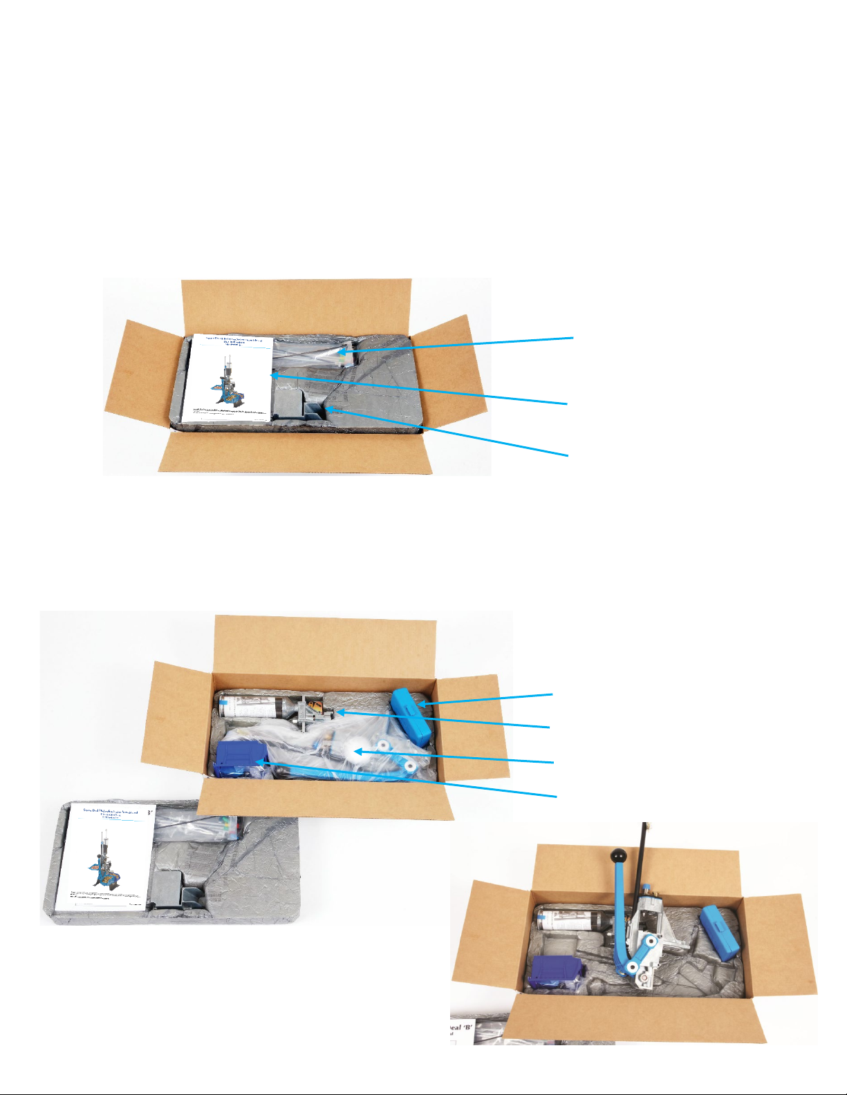
4. SQUARE DEAL “B” SHIPPING CONTENTS
4.1. Remove the following items from the top protective foam layer of the Square Deal “B” shipping
box:
4.2. Remove the following items from the second layer of protective foam
•Primer Early Warning System,
Follower Rod, Battery and
Tube Pack
•Square Deal “B” System
Manual
•Square Deal Chute and Bin
Bracket
•Square Deal “B” Conversion Box
•Dillon Powder Measure
•Square Deal Press
•
Bin and Accessory Bag

6
4.3. Contents of Square Deal “B” Shipment
5. SQUARE DEAL “B” ASSEMBLY GUIDE
5.1 To mount the Square Deal “B”, select a clear area on your reloading bench. Your bench must be strong
enough to support the weight and the force required to operate the Square Deal “B”. If possible, attach
your bench to the wall. Remove the Square Deal “B” Reloader from the packaging and place it on your
selected area. You will need 7/16” wrenches, a drill motor and a 9/32” drill bit and the included Allen
wrenches.
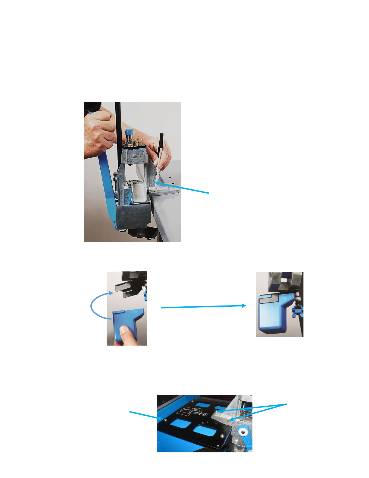
5.2 Locate the provided Ejected Cartridge Chute/Bracket and two ¼-20 x 3/8” Socket Head Mounting Screws
and fasten the Bracket to the side of the Square Deal “B” as shown:
5.3 Locate the provided Spent Primer Bracket and two 8-32 x 3/8” Button Head Mounting Screws and mount
Spent Primer Cup Bracket securely to the bottom of the Square Deal “B” as shown below:
1. Primer Early Warning System and
Primer Follower Rod
2. Caliber Conversion Box—Parts
installed
3. Tube Pack accessory parts bag—
Primer Pickup and Magazine
Tubes, and Spare Tips—Large
Tube Pack PN22016
Small Tube Pack PN22017
4. Powder Measure
5. Completed Cartridge Bin
6. Square Deal “B” with Caliber
Specific Dies Installed
7. Used primer cup and Powder
Measure Return Bracket
8. Ejected Cartridge Chute and
Completed Cartridge Bin Bracket
9. Large Powder Bar (Small Bar
installed in Powder Measure)
10. Included Allen Wrenches
11. Square Deal “B” Instruction
Manual
Mount
Ejected
Cartridge
Chute
Bracket
Mount
Spent
Primer
Cup
Bracket
Spent Primer
Cup Bracket
and Screws
Cartridge
Chute/Bracket
and Mounting
Screws
7
5.4 The Square Deal “B” can be mounted directly to your bench (If you are using the Dillon Strong Mount
proceed to 5.4.4 below). The preferred method of operating the Square Deal “B” is standing up. This
gives you the leverage for the force needed to properly seat primers.
5.4.1 For mounting directly to a bench, bring the Square Deal “B” to the forward edge of your bench as shown
below. The Square Deal “B” requires ¾” clearance under the front edge of the bench. See below.
5.4.2 Mark the three mounting holes using the Square Deal “B” as a template. Remove the machine and drill
three 9/32” holes through the bench. Bolt the Square Deal “B” securely to the bench with ¼” Grade 5
hardware or available Dillon Mounting Hardware Kit P/N14355. Use small diameter washers on the top
and large diameter washers on the bottom, especially if using a wooden bench.
5.4.3 Slide the Spent Primer Cup into the mounting slots on the Bracket.
.
5.4.4 There are three other optional methods for mounting the Square Deal “B” to your bench.
•The first option is to use the available Billet Dillon Mounting Plate PN62005 by fastening the Plate to
your bench and then mounting the Square Deal “B” to the Plate and as shown below:
Mount Square Deal “B” with Base Mounting
Flange tight against the bench making sure there
is clearance below for the Crank, Operating
Handle and the Spent Primer Cup
Slide Cup on
Bracket
Square Deal “B”
mounted directly to
Dillon Mounting Plate
with two ¼”-20 x 3/4”
Screws and one ¼”-20 1
¼ “Screw
Dillon Billet Mounting
Plate fastened to your
bench

8
•The second method is to install the Square Deal “B” on the Dillon optional Strong Mount using The
Dillon Strong Mount Kit PN62395 and then mount the Strong Mount to the bench. Installation
instructions are included with the Strong Mount. The Dillon Strong Mount improves the stability of the
system by distributing the loading forces over a larger area of the bench and provides mounting
locations for an optional Empty Case Bin and the provided Completed Cartridge Bin.
•The Third method is to fasten the Strong Mount with the Square Deal “B” to the optional Dillon Billet
Mounting Plate PN62006 and then fasten the Billet Mounting Plate to the Bench as shown below.
5.4.5 Install the completed Cartridge Bin on the Chute/Bin Bracket of the Strong Mount by sliding the lip on the
bin over the bracket and the lip of the Empty Case Bin over the other bracket as shown below.
5.4.6 Install the optional Dillon Bullet Tray PN22214 on the left side of Strong Mount in the two holes as shown
below with the hardware provided with the Bullet Tray Kit.
Dillon Billet Mounting
Plate fastened to the
bench—4 places
Fasten Strong Mount to Billet
Mounting—4 places
Square Deal “B” with Strong
Mount PN62395 and Dillon
Billet Mounting Plate
PN62006
Fasten Strong
Mount directly to
the bench in each of
the 4 corners
Completed Cartridge Bin
Bracket
Empty Case Bin Bracket
Mount Bullet Tray PN22214
with provided Screws,
Washers and Nuts
Dillon Square Deal
“B” Strong Mount
Kit with Empty
Case Bin and
Mounting
Hardware
PN62395
Empty Case Bin
Completed
Cartridge Bin

9
5.4.7 Install the optional Dillon Tool Holder with Wrench Set PN19441 as shown below. Remove the two 7/16”
Hex Mounting Screws and nuts underneath for the Square Deal” B” and install the Tool Holder using the
same two screws and nuts and tighten securely. Insert the Allen wrenches and Bench Wrench in their
appropriate labeled positions in the Tool Holder.
5.5 Install the Powder Measure
5.5.1 Remove the Blue shipping Cap from the Powder Die. Retrieve the Powder Measure from the shipment and
remove the Powder Measure Clamp Screw and Clamp using the provided Allen wrench.Note--The
Powder Funnel for the cartridge specified for the Square Deal purchased ships in the Powder Die.
5.5.2 Slide the Square Deal “B” Powder Measure down over the Powder Die and install the Clamp and lightly
tighten the Clamp Screw. Further adjustment of the Powder Die is required later.
Install Powder
Measure oriented
as shown and
lightly tighten the
Clamp Screw with
the provided Allen
wrench
Mount Tool Holder
with Wrench Set
PN169441 using the
two existing Square
Deal Mounting
Screws, Washers
and Nuts
Remove the Blue Cap
from the Powder Die
Remove the Powder
Measure Screw and Clamp
The Powder Funnel is shipped/installed
inside the Powder Die
Place Powder
Measure down
over the top of
the Powder Die
10
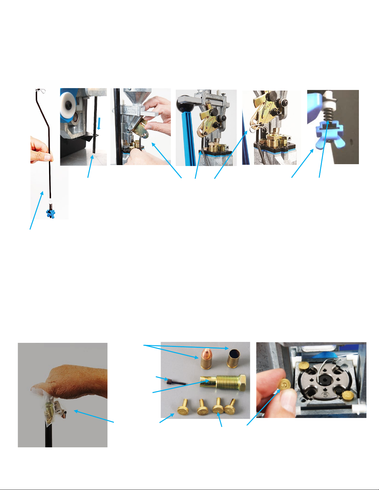
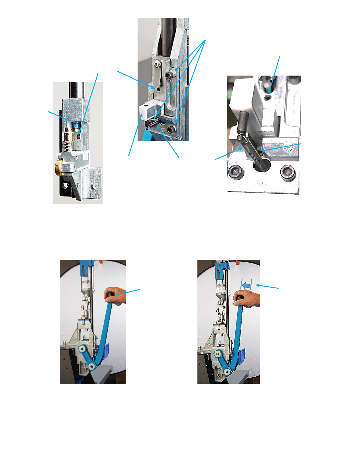
5.5.3 Locate the Failsafe Powder Measure Return Rod in the shipment and remove the top Spring Clip and the
lower Blue Wing Nut, Spring and Bushing. Rotate the Powder Measure, aligning the Failsafe Rod vertically
with the Failsafe Rod Bracket as shown below. Install the bottom threaded section of the Rod down
through the hole in the Failsafe Bracket on the bottom of the Square Deal and slide the top hook through
the hole and slot in the Lock-link Assembly of the Powder Measure. Reinstall the Spring Clip as shown
below. Reinstall the White Bushing, Spring and Wing Nut on the Bottom of the Rod. Cycle the Operating
Handel of the Square Deal “B” all the way down compressing the Failsafe Rod Spring. Adjust the Blue
Wing Nut up leaving .030” of clearance (two credit card thicknesses) between coils when fully compressed.
Re-adjustment may be necessary after setting the case mouth belling discussed later.
5.6 A plastic bag is secured to the top of the Primer Magazine Shield Tube and contains four (one spare)
numbered Brass Locator Buttons for the caliber ordered, a spare Depriming Pin, an alternate Seating Stem
(Two for .38/.357’s), a sample case with a primer and a sample reloaded cartridge showing how the press
was configured. Take three of the Brass Locator Buttons and install them in the Square Deal as shown
below.
Failsafe Return Rod
Assembly –Remove
Spring Clip and Blue
Wing Nut, Spring
and Bushing
Insert Failsafe
Return Rod
Assembly down
through hole in
Failsafe Bracket
Slide the Failsafe
Return Rod Hook
through the slot and
hole in the Lock-link
Assembly and
reinstall the Spring
Clip
Reinstall the White
Bushing, Spring
and Wing Nut on
the Bottom of the
threaded Rod
Cycle the Operating
Handle down and
adjust the Wing Nut
to leave .030”
clearance between
the coils of the Spring
when compressed
Brass Locator Buttons--Caliber specific—Install
3 in Square Deal “B” as shown (1 spare)
Sample
primed case
and cartridge
Spare
Depriming Pin
Alternate
Seating Stem
Bag Fastened to
Primer Mag
Shield—Contents

11
5.7 Note: The Square Deal ships with the Primer System size installed for the cartridge ordered. The
alternate small or large Primer Assembly is shipped in the Accessory box. Refer to Section 8.3 on the
Primer Conversion Procedures for changing primer size.
5.8 Install the Primer Early Warning System
5.8.1 The Primer Early Warning system emits a “beeping” sound when the Primer Magazine is down to the last
three or four primers.
5.8.2 Simply push the Primer Early Warning System down over the Primer Magazine Shield Knurled Cap until it
stops.
5.8.3 WARNING! Do not put primers in the Magazine Tube until you have read this entire manual.
5.8.4 Install the Primer Magazine Follower Rod as shown below. You can store the plastic Primer Follower Rod
in the Magazine Tube when there are no primers in the Magazine Tube by putting it under the Operating
Lever to stop the alarm from sounding when it is not being used.
5.9 Your assembly is complete. Cycle the Operating Handle making a full stroke down and up again and push
fully to the rear to the priming position. The Shellplate should index clockwise. The Primer Slide should
move back and forth and the Primer Punch will project up through the hole in the Shellplate.
Store Rod as
shown to
disable the
audio alert
when no
primers are
present
Press EWS down over the Knurled Nut
Install Follower
Rod

12
6. OPTIONAL EQUIPMENT FOR THE SQUARE DEAL “B”:
•Square Deal Strong Mount and Case Bin: PN22051
•Tool Holder with Wrenches: PN19441
•Low Powder Warning Sensor: PN16306
•Square Deal “B” Toolhead Assy: PN20113
•Deluxe Quick Change & Stand: PN62265
•Spare Parts Kit: PN97015
•Bullet Tray: PN22214
Note-- Conversion Kit
Shellplate and Dies sold
separately

13
7. THE DILLON SQUARE DEAL “B” HAS FOUR RELOADING STATIONS AND USES UNIQUE DIES
AND A POWDER MEASURE ASSEMBLY. The Toolhead and Shellplate are specific to the Square
Deal” B” and are not compatible with any other dies or reloading system—see the description of the
four stations and the operations below:
•STATION 1—DEPRIME AND SIZE CASE--(Number 1 engraved in the Toolhead)
•STATION 2--SEAT PRIMER, BELL CASE MOUTH AND DISPENSE POWDER (Number 2 in the Toolhead)
•STATION 3--SEAT BULLET--(Number 3 in the Toolhead)
•STATION 4--CRIMP BULLET AND EJECT COMPLETED CARTRIDGE--(Number 4 in the Toolhead)
Note--cases are automatically indexed from station to station every time the Operating Handle is cycled down and
up.
Station 1
Station 2
Station 4
Station 3
Station 4
Station 1
Station 2
Station 3
Each Station is numbered on the
Toolhead 1 thru 4 as are the Size
Die #1, the Seat Die #3 and the
Crimp Die #4
Station 1-Size
and Deprime
Station 2-Prime and
Dispense Powder
Station 3-
Seat Bullet
Station 4-Crimp Bullet
and Eject Cartridge
Toolhead Assembly
with Blue Friction Plate
Square Deal Powder Measure
and Clamp Assembly
Square Deal Powder
Die and Clamp
14
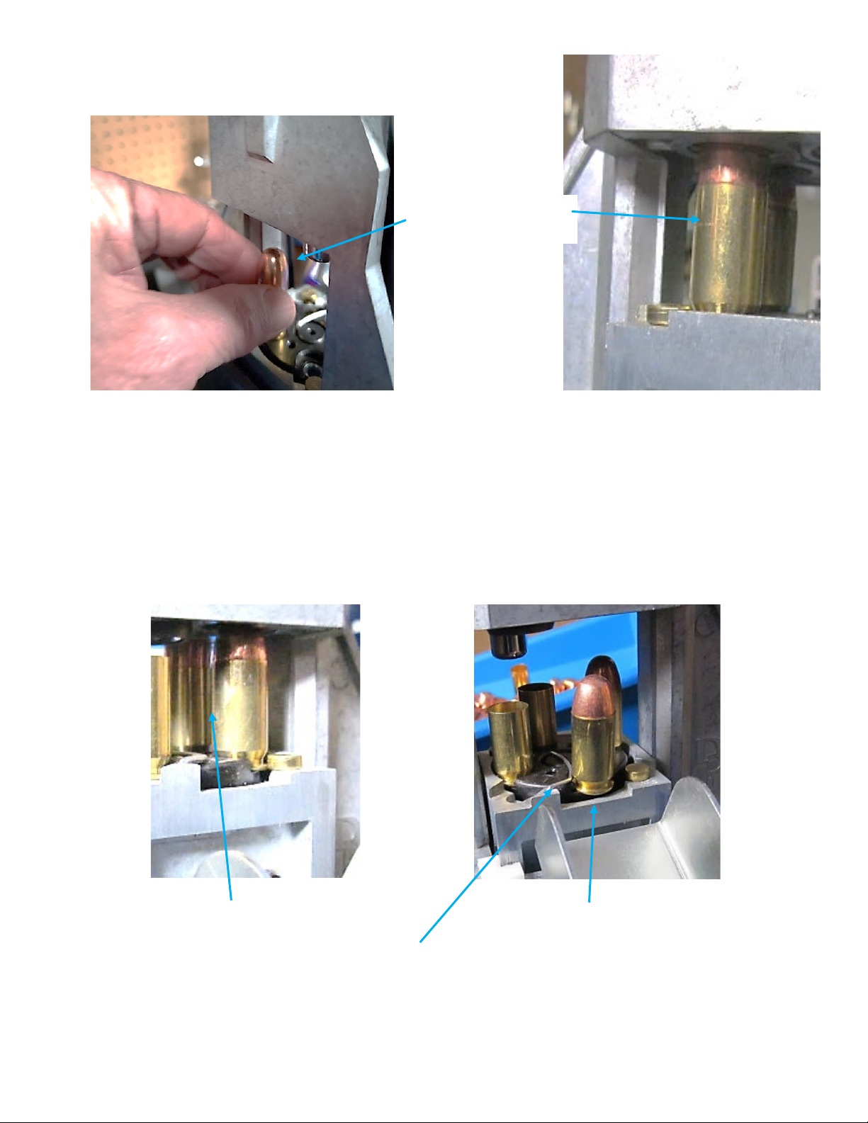
7.1. Station 1— Case is Deprimed and Sized
•The user inserts a case into the Shellplate
•Cases are de-primed and sized on the downstroke of the Operating Handle
•On the upstroke, the case is indexed to Station 2 and a Primer is picked up by the Primer Slide and fed into
Station 2
Station 1—Case Deprimed and Sized
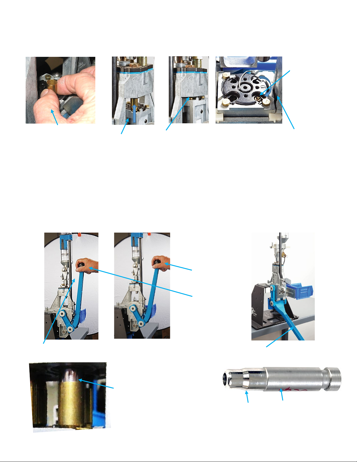
7.2. Station 2—Primers Are Automatically Fed and Seated, The Case Is Flared (Belled) and the Powder
Dispensed
•Primers are seated on the “full-push stroke” of the Operating Handle from the “at-rest” position of the
Operating Handle
•On the downstroke, the case mouth is belled (flared) and powder dispensed into the case
•On the upstroke, the case is automatically indexed to Station 3
Station 1--Case entering Depriming/Sizing
Die as the Operating Handle is lowered
raising the Shaft/Shellplate
Station 2—Primer Seated, Case Flared, Powder Dispensed
Station 1--Case manually
inserted into Shellplate
Station 2—Case being pushed over
the nose of the Powder funnel
belling the case mouth and dropping
powder into the case
Station 2— Typical
Dillon Powder Funnel—
fits inside the Powder
Die
Station 1—On the upstroke the case is indexed to
station 2 and a primer is picked up and presented to
Station 2
Case not shown
in Station 2 for
clarity
Station2--Primer seated push stroke of the Operating Handle
from the at rest position
Neutral
“at-rest”
Position
Primer
seating
position
Station2--Case mouth flared and powder dispensed
on the down stroke of the Operating Handle
Belling Feature of
Powder Funnel
15
7.3. Station 3—Bullet Placed and Seated
•User places bullet on the case in Station 3
•On the downstroke, the bullet is seated
•On the upstroke, the case is automatically indexed to Station 4
7.4. Station 4—Bullet Crimped and Completed Cartridge Ejected.
•The Bullet is crimped on the downstroke
•The Cartridge is ejected on the upstroke
Station 3--Bullet Placed
and Seated
Station 3—Bullet Seating
Ejector Wire Ejects Cartridge
into Cartridge Chute/Bin
Station 4 (Crimp)
Station 4 (Eject)

16
8. SETUP PROCEDURES FOR SQUARE DEAL “B”—WARNING! Due to variations in components, check
all stations for proper adjustments for the cartridge you are loading. You must read the following
instructions. If there is something you do not understand, call (800) 223-4570 for technical assistance.
8.1. The Dies and Toolhead are unique to the Square Deal.
8.3.1 The Dies are numbered #1-Size Die, #3-Seat Die and #4-Crimp Die. They drop into the Square Deal Frame
Station #1, #3 and #4 respectively as shown below.
8.2. Another unique part of the Square Deal Toolhead Assembly is the Blue Friction Plate which is sandwiched
between the Frame below and the Numbered Toolhead above. The Friction Plate keeps the threaded parts
of the dies from easily turning. The remaining parts are assembled as described below:
Station #1--Size
Station #3--Seat
Station #4--Crimp
Friction Plate
Numbered Toolhead
Square Deal “B” Toolhead Assembly

17
8.3. Station 1—Sizing and Depriming
8.3.1 There is no adjustment required for Station 1--The Size Die with its Carbide insert drops into Station 1 and is
secured by the Toolhead. The Depriming Assembly threads flush into the Toolhead. The Deprime and Size
Components are shown below. The case is sized and Deprimed in Station #1 on the downstroke of the
Operating Handle.(Note—a Primer is picked up by the Primer Slide in Station #2 during the downstroke of the
Operating Handle during the Sizing/Depriming Operation in Station #1).
8.4 Station 2a--Primer Feeding, Seating, Case Belling and Powder Dispensing--The First Operation of Station 2 is
(a) to seat a primer on the full push stroke of the Operating Handle. The Second Operation of Station 2 is to
(b) expand the case mouth and dispense powder on the downstroke of the Operating Handle.
8.4.1 The Square Deal “B” incorporates an Automatic Linear Primer Feed System utilizing standard Large or Small
Primer Magazine Tubes and interchangeable Large and Small Primer Slides. The Square Deal “B” comes with
the primer size specific to the cartridge ordered. The alternate size Primer Slide is shipped separately. A Large
Powder Bar for the Powder Measure is also included. These components are in the “Tube Pack” --see shipping
contents.
8.4.2 A Primer Early Warning System (EWS)/Low Primer Alarm system is provided. The Primer Follower Rod is the
Actuator for the Primer Early Warning System.
8.4.3 A primer is automatically picked up by the Primer Slide and Primer Cup Assembly from the Primer Magazine.
It is then positioned under the hole in the Shellplate in Station 2 as the case is indexed from Station 1 during the
upstroke of the Operating Handle. The Primer is then seated with a complete push stroke of the Operating
Handle.
Size Die drops
into the
Square Deal
Primer pushed up by Primer
Punch ready to be installed
if a case was present
Large Primer
Slide Assembly -
-Silver Cup
Primer Follower Rod and
Assembly and Primer Early
Warning System
Depriming Assembly threads
down against the Tool head
Primer Follower Rod
showing there are
Primers left in magazine
Tube
18
8.4.4 The Operation of The Automatic Primer System
•The Square Deal “B” comes set up in the primer size for the cartridge ordered.The alternate size
Primer Slide Assembly ships separately.
•Primers are seated by pushing the Operating Handle fully to the rear, from the Operating Handle’s
“at rest position” at the top of the Square Deal’s stroke.
•CAUTION!
•Learning to feel the correct force to seat a primer is a critical method in the reloading process.
•The Prime will not be seated to the proper depth if the Handle is not pushed firmly and fully to
the rear primer seating position.
Primer Slide in primer
pickup position—
Operating Handle Down
Primer
Magazine
Blue Tip
Operating
Handle
“at-rest
position
Primer Slide
return Spring
Primer Slide
Forward
Travel Set
Screw Stop—
Primer
seating
position
Adjustable
Set Screw
Stop-Primer
pickup
position
Primer
Assembly
Mounting
Screws
Primer Slide in primer
pickup position—Rear
Travel Adjustable Set
Screw Stop
Push Handle fully
to the rear to seat
a primer

19
•If the primer takes too much force to be seated and the Handle cannot be pushed fully
to the rear—STOP and inspect the case. The primer pocket may be damaged or could
have a crimped primer pocket or the Primer Cup may not be aligned properly with the
Shellplate.
•Low resistance to seating a primer can indicate an enlarged primer pocket that may
not retain the primer. Discard this case.
•Verify that the system feeds primers as follows:
•Remove the plastic Follower Rod and unscrew the Magazine Cap.
•Remove and verify the Magazine Tube is of the correct size/color--The blue tip for
small primers and the red tip for large primers. Note: Any primers left in the
Magazine Tube will fall out in the Magazine Shield Tube.
•Install the Magazine Tube in the Magazine Shield. The tab on the plastic Magazine
Tip, red or blue, must be gently aligned with the slot down in the Primer Feed Body
Housing and then should slide down about a 1/4” more. Tighten the knurled
Magazine Cap just snug.
•With the Operating Handle up in its at-rest position, manually take one primer that
you will be using and drop it anvil side up in the hole in the Magazine Cap as below:
•Cycle the handle smoothly down and back up to the top of the stroke to the “at rest position.”
•The primer should present itself in the Priming Station on top of the Primer Punch as shown below—
repeat this step 3 times--if successful proceed to the next step, if not, proceed to Primer Drop Alignment
Section 10.2.
Drop one primer in
Magazine Shield/Cap
Correct presentation
of primer—Single
primer drop test—
Primer ready to be
seated Station 2
Magazine Tip Alignment Tab
Tighten knurled
Magazine Cap
just snug
Magazine Cap fits over
end of Magazine Tube
Red Large Tip and Magazine Tube
Blue Small Tip and Magazine Tube

20
8.4.5 Verify Primer Seating Depth
•With a primer in the cup as above and the Operating Handle in its up at-rest position, put a de-
primed case in Station 2. Push the Operating Handle fully to the rear seating the primer. Remove
the case and verify the primer is seated flush or slightly below flush.
•The primer seating depth is an important parameter to control when reloading and can be a safety
issue. The ideal seating depth is .002” to .006” (.008” Max) below the case head. WARNING!
“High” or protruding primers can lead to slam fires in semi-autos or firing out of battery and can
stop the cylinder from rotating in revolvers. Seating the primer too deep can cause damage to the
primer, causing misfires and or inconsistent ignition. Refer to Section 14 on Primer Basics.
8.4.6 Filling the Primer Magazine-- Dillon offers two choices for filling the primer magazine:
•Manually as below with an optional Dillon Primer Flip Tray and Dillon Primer Pickup Tubes. Pickup
Tubes are included with the Square Deal “B”.
•The Primer Pick-Up Tubes have different colored tips. They have been color-coded to identify size
easily. The color code is as follows:
•WARNING! Put on safety glasses!
•Place primers on the half of the Flip Tray with the ribs. Oscillate the tray and primers around until all
the primers are flat. Pick up all the primers that are shiny side up by placing the Plastic Pickup Tip—
yellow or green, over the shiny side up primers in the Primer Flip Tray and gently pressing down. Put
the other half of the Flip Tray on the ribbed half with the primers that are anvil side up. Hold the two
Primer Pickup Size Pickup Tip Color Dispense Tip Color
Small Yellow Blue
Large Green Clear
Courtesy of Western Powders
Primer on right is
seated properly--
the one on the
left is high
Table of contents
Other Dillon Precision Products Industrial Equipment manuals


Popular Industrial Equipment manuals by other brands


HBM
HBM C16A Series installation instructions

steute
steute STM 295 Mounting and wiring instructions

KINSHOFER
KINSHOFER KM 506 HD operating instructions

KTR
KTR SYNTEX Hub design 1.0 Operating & assembly instructions

eXact
eXact PipeCut Infinity operating instructions

Sumitomo
Sumitomo Taper Grip installation guide


