KTR Kupplungstechnik
GmbH
D-48407 Rheine
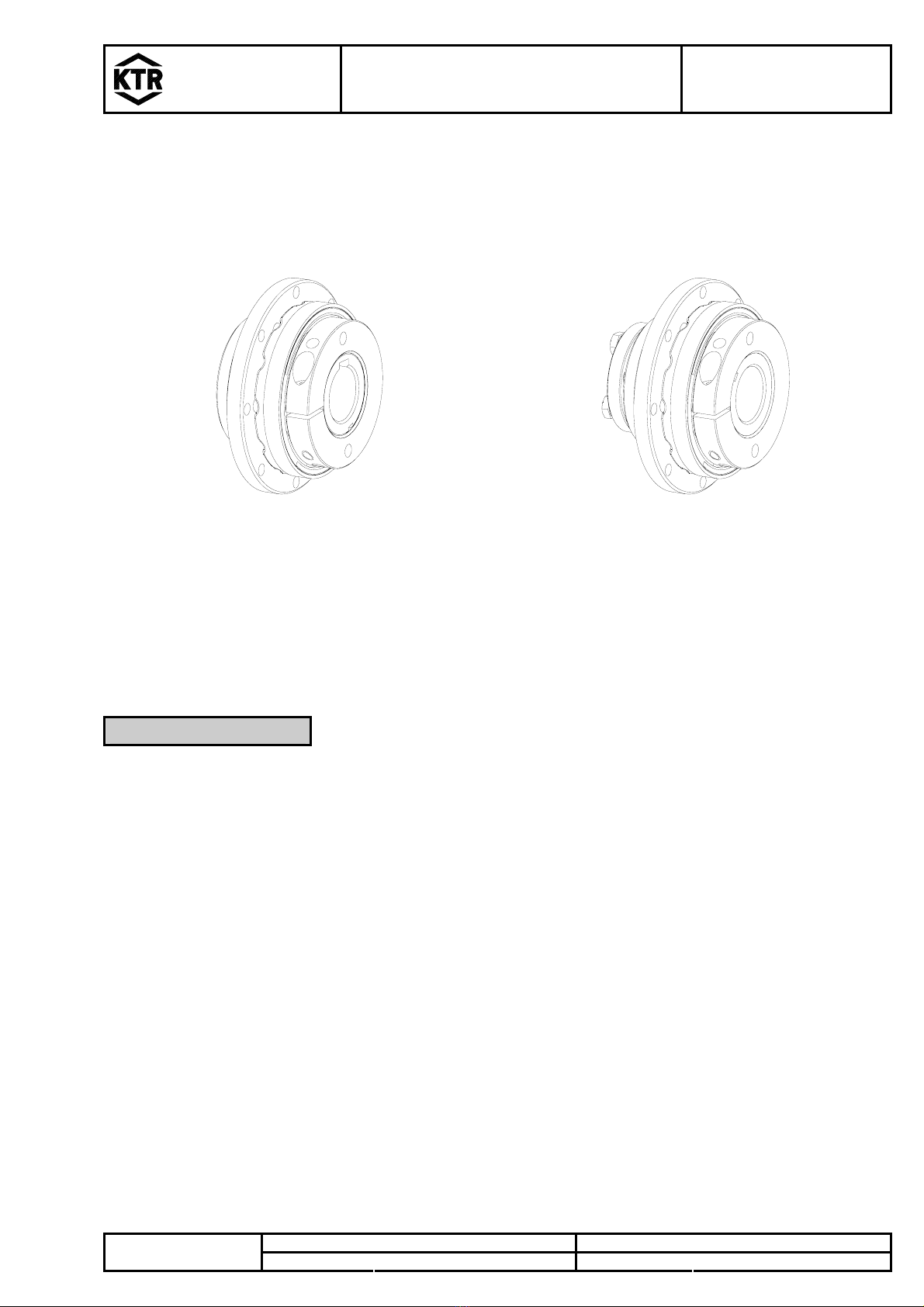
SYNTEX®
Operating-/Assembly Instructions
design DK (ratchet)
KTR-N
sheet:
edition:
46210 EN
3 of 8
6
Gezeichnet: 30.06.10 Li/Lm Ersatz für: KTR-N vom 17.03.10Schutzvermerk
ISO 16016 beachten. Geprüft: 30.06.10 Li Ersetzt durch:
2 Hints
2.1 General Hints
Please read through these mounting instructions carefully before you set the coupling into operation.
Please pay special attention to the safety instructions!
The mounting instructions are part of your product. Please keep them carefully and close to the coupling.
The copyright for these mounting instructions remains with KTR Kupplungstechnik GmbH.
2.2 Safety and Advice Hints
STOP
DANGER! Dangerofinjurytopersons.
! CAUTION! Damagesonthemachinepossible.
)A TTENTION! Pointing to important items.
2.3 General Hints of Danger
STOP
DANGER!
With assembly, operation and maintenance of the coupling it has to be made sure that the
entire drive train is protected against unintentional engagement. You can be seriously hurt
by rotating parts. Please make absolutely sure to read through and observe the following
safety instructions.
•All operations on and with the coupling have to be performed taking into account "safety first".
•Please make sure to disengage the power pack before you perform your work.
•Protect the power pack against unintentional engagement, e. g. by providing hints at the place of engagement
or removing the fuse for current supply.
•Do not touch the operation area of the coupling as long as it is in operation.
•Please protect the coupling against unintentional touch. Please provide for the necessary protection devices
and caps.
2.4 Proper Use
You may only assemble, operate and maintain the coupling if you
•carefully read through the mounting instructions and understood them
•had technical training
•are authorized to do so by your company
The coupling may only be used in accordance with the technical data. Unauthorized modifications on the coupling
design are not admissible. We do not take any warranty for resulting damages. To further develop the product we
reserve the right for technical modifications.
The SYNTEX®described in here corresponds to the technical status at the time of printing of these mounting
instructions.