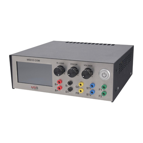
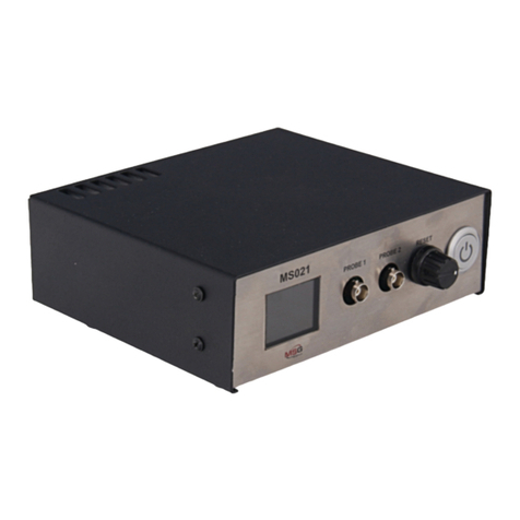
MSG MS015 COM User manual

MS015 COM
USER MANUAL
TESTER FOR AUTOMOTIVE
ALTERNATORS
РУКОВОДСТВО ПО ЭКСПЛУАТАЦИИ
ТЕСТЕР ДЛЯ АВТОМОБИЛЬНЫХ
ГЕНЕРАТОРОВ
UNIQUENESS
QUALITY SERVICE
WARR ANTY TRAINING
INNOVATION
2020.03.17
INSTRUKCJA OBSŁUGI
URZĄDZENIE DIAGNOSTYCZNE DO
TESTOWANIA GENERATORÓW


1
User Manual - MS015 COM Tester
English
INTRODUCTION ..........................................................................................................................................................2
1. APPLICATION ......................................................................................................................................................... 2
2. TECHNICAL CHARACTERISTICS.......................................................................................................................... 3
3. EQUIPMENT SET.....................................................................................................................................................4
4. DESCRIPTION..........................................................................................................................................................4
4.1 Tester menu....................................................................................................................................................6
4.2 Alternator testing modes.............................................................................................................................7
5. INTENDED USAGE...................................................................................................................................................9
5.1 Safety measures.............................................................................................................................................9
5.2 Testing of the alternator assembly in the car....................................................................................10
6. TESTER MAINTENANCE ......................................................................................................................................11
6.1 Firmware update..........................................................................................................................................11
6.2 Cleaning & Care...........................................................................................................................................12
7. MAJOR FAULTS AND TROUBLESHOOTING TECHNIQUES...........................................................................12
8. EQUIPMENT DISPOSAL ......................................................................................................................................13
APPENDIX 1 ...............................................................................................................................................................14
APPENDIX 2 .............................................................................................................................................................48
CONTENT

2
Thank you for choosing MSG Equipment product.
MSG MS015 COM Tester for diagnostics of automotive alternators is made of high-quality
components and material through the use of advanced techniques of diagnostic equipment
manufacture.
The User Manual contains information concerning MS015 COM usage, equipment set, design,
function, technical characteristics and operation.
The Manufacturer reserves the right to change the design and software of the equipment without
prior notice to users.
Read carefully User Manual before putting MS015 COM (hereafter referred to as tester) into use.
Take a special training at the equipment manufacturing facility if necessary.
MS015 COM Tester is designed to diagnose automotive alternators with a supply voltage of 12V in
two ways:
• directly in the car;
• on the diagnostic test bench which provides its drive.
INTRODUCTION
1. APPLICATION
User Manual - MS015 COM Tester
English

3
2. TECHNICAL CHARACTERISTICS
3. CONTROL DEVICES
General
Dimensions (L*W*H), mm 120×65×18
Weight, kg 0,15
Supply voltage, V from 10 to 18
TFT-LCD Touch screen, color 2.8” screen size
Operating temperature, ˚C from 0 to +40
Storage temperature, ˚C from 0 to +40
Ingress protection rating IP20
Alternator testing
Types of tested alternators «COM» («LIN», «BSS»), «SIG», «RLO», RVC»
«C KOR.», «P-D», «C JAP.».
Tested parameters
- Stabilizing voltage
For COM voltage regulators:
- ID;
- Protocol type
- Exchange rate
- Errors
Supply voltage of tested alternators, V 12
Polarity reversal protection Yes
Short-circuit sound alert No
Battery pack No
User Manual - MS015 COM Tester
English

4
MS015 COM Tester set includes:
• MSG MS015 COM Tester – 1 pc.;
• MS0128 – Set of diagnostic cables:
• Four-wire cable - 1 pc.;
• Cable for connection of additional "+" - 1 pc.;
• User Manual – 1 pc.
Observe MS015COM Tester. If any damage is detected, please contact the manufacturer or sales
representative before launching the equipment.
3. EQUIPMENT SET
4. DESCRIPTION
WARNING! In case of obvious damage, the operation of the equipment is forbidden.
Fig.1. MS015 COM Tester. General view.
User Manual - MS015 COM Tester
English

5
The tester is a compact device supplied with a touch screen. A connector for diagnostic cable
connection is located in the upper part of the tester (Fig. 2), a MicroSD connector for software
updates - in its lower part (Fig. 3).
Two diagnostic cables are also included in the equipment set (Fig. 4, 5): a diagnostic cable and an
auxiliary cable to connect an additional positive contact.
Fig. 2. Connector for diagnostic cable.
Fig. 4. Four-wire diagnostic cable.
Fig. 3. MicroSD connector.
User Manual - MS015 COM Tester
English

6
The cable has the following marking:
"GC" (Yellow) is intended for connection to the alternator voltage control terminal.
"FR" (Green) is intended for connection to the alternator load control terminal.
"-" (Black) - "B-." Battery negative pole (the alternator housing).
"+" (Red) - "B+". Battery positive pole, the alternator output. Used to power the device when
testing the alternator on the test bench or in the car; it is also used for “B+” voltage indication.
The main menu consists conditionally of three sections (Fig. 6):
Fig. 5. Cable for connection of additional “+”.
Fig. 6. Tester main menu.
4.1 Tester menu
1
2
3
User Manual - MS015 COM Tester
English

7
The following information is displayed when the testing mode for COM-type alternator is selected
(Fig. 7):
1 – Selection of the alternator type. The alternator type can be selected by single-clicking on the
corresponding icon. The selected type is being highlighted.
2 – Types of voltage regulator connectors are displayed as reference information.
3 – "HELP" and "TEST" buttons. Customer support contact information is displayed when the
"HELP" button is pressed. Alternator testing mode is on when the "TEST" button is pressed.
4.2 Alternator testing modes
Fig. 7. Diagnostic window of the “COM”-type alternator.
1) Type of the tested alternator;
2) “-V” and “+V” buttons are used to set the voltage on the voltage regulator, which is displayed
as "set + numerical value". Each pressing of the button changes the value of preset voltage by
0.2V. The measured voltage is displayed in green below the preset voltage.
3) “COM PR.”: voltage regulator protocol type. The following protocol titles appear on the display:
LIN1.3 (displayed as LIN1), LIN2.0 (displayed as LIN2).
4) “ID”: voltage regulator identication number. The manufacturer and the voltage regulator order
number are encoded in it. The ID number should correspond to the original one, when mounting
the voltage regulator on the car, otherwise the car will reject such a voltage regulator and the
dashboard will display an error.
5) “COM SPEED”: speed of data exchange between the voltage regulator and vehicle ECU. The
following speed rates can be displayed in the "LIN" protocol:
User Manual - MS015 COM Tester
English

8
• “L” – 2400 baud (low);
• “M” – 9600 baud (medium);
• “H” – 19200 baud (high).
6) “TYPE” - voltage regulator connection type. The following protocol types are displayed: “BSS”
or one of the 12 types of “LIN” protocol: A1, A2, A3, A4, B1, B2, B3, B4, C3, D1, D2, E1.
7) "EXCITATION" – stator excitation level (load).
8) “ERROR” –voltage regulator operation errors. There are three types of potential errors:
• “EL” – electric error;
• “ME” – mechanic error;
• “TM” – thermal error.
When detected, the error is indicated in red.
9) “BACK” –diagnostic mode exit.
The following information will be displayed when the testing mode for one of the alternator types
("SIG”, “RLO”, RVC”, “C KOR.”, “P/D”, “C JAP.”) is selected: (Fig. 8):
1) Type of the tested alternator.
2) "-V" and "+V" buttons are used to set the voltage on the voltage regulator which is displayed as
"set + numerical value". Each press of the button changes the voltage value by 0.2V. The measured
voltage is displayed in green below the set voltage.
3) “FR” – Field response.
4) “DFM” – DFM – digital eld monitor.
Fig. 8. Alternator diagnostic window when one of the following alternator
types “SIG”, “RLO”, RVC”, “C KOR.”, “P/D”, “C JAP.” is selected.
User Manual - MS015 COM Tester
English

9
WARNING! Contact the MSG Equipment support team in case you want to connect the type of
alternator which is not on the list.
1. The tester is intended for indoor use. When used outdoor, external conditions and technical
characteristics of the device set out in item 2 of this manual, should be taken into consideration.
2. To avoid damage or failure of the tester, do not make any changes in the electrical diagram of
the device. In case of failure, please contact Technical Support or a sales representative.
3. The device enables to test the alternator assembly either directly on the car or on the test
bench, which provides its drive. Further on, the option of testing the alternator directly on a car
will be looked into. Diagnostics with the test bench is performed quite the same way.
1. Only the personnel that has received special training in safety operation and been authorized
to work with the particular equipment is allowed to use the device.
2. Make sure that measuring clamps do not have insulation damage or bare metal spots. Check
the clamps for any breaks. In case of obvious damage, replace them with new ones before
launching the device.
3. In order to avoid possible electric shock or injury as well as damage to the tester, do not apply
voltage exceeding 20V to the device outputs (or between the earth and any of the outputs).
4. When measuring, try to connect outputs correctly, especially “B-“ones. The device has all kinds
of protection against emergency situations, however not all voltage regulators have such a
protection.
5.1 Safety measures
5. INTENDED USAGE
5). An oscilloscope is displayed on the screen and shows the measured signal and its waveform.
The measured signal is displayed on two scales: 20 and 200ms. Single-click on the diagram to
switch from one scale to another.
User Manual - MS015 COM Tester
English

10
WARNING! Testing of the alternator on a car should be performed on premises equipped
with combined extract and input ventilation or fume offtake system. Alternatively, all the
measurements should be carried out outdoor.
5.2 Testing of an alternator on a car
WARNING! It is prohibited to exit the testing mode when the engine is running. Otherwise it
will result in a sharp surge of voltage generated by the alternator.
WARNING! In case of spontaneous disconnection of the black (“B-“, battery negative
terminal) and/or red (“B+”, battery positive terminal) clamp it is strictly prohibited to connect it
again when the engine is running.
User Manual - MS015 COM Tester
English

MS015 COM is designed for a long-term operation 24/7. However, to ensure the test bench uptime,
it is necessary to provide regular technical inspection and below described routine maintenance
of the device.
Below are the main points that should be checked during a daily inspection:
• Environmental conditions for the tester operation (temperature, humidity, air pollution,
vibration, etc.).
• Condition of the wires that should be connected to the device outputs (visual inspection).
• Do not store or use the device in places exposed to high temperature, humidity, danger of
explosion or re, strong magnetic eld. Exposure to dampness may degrade the product's
performance.
6. TESTER MAINTENANCE
Update MS015COM software as follows:
- Download a new version of the software.
*File with the latest software version can always be found on our website: servicems.eu.
- Copy it to the root of 32 Gb MicroSD drive formatted in FAT32.
- Switch the tester off and insert the drive into the MicroSD connector of the device.
- Switch the tester on by connecting the red wire to the battery plus and the black one to its
minus, or connect the device to 12V DC power supply.
- On launch, the device will automatically detect a new version of the software and start the
installation.
•Wait until the installation is completed.
- The device will boot up upon nishing the installation.
- Switch the device off.
- Extract the MicroSD drive.
6.1 Tester software update
11
User Manual - MS015 COM Tester
English
WARNING: Do not interrupt the software update process by disconnecting the unit or
removing the MicroSD drive.

12
Soft tissues or wipe cloths should be used to clean the surface of the device with neutral
detergents. The display should be cleaned with a special ber cloth and a screen cleaning spray.
No abrasives or solvents should be used to prevent corrosion, failure or damage to the tester
Possible malfunctions and ways to x them are described in the below table:
6.2 Cleaning & Care
7. MAJOR FAULTS AND TROUBLESHOOTING TECHNIQUES
Failure symptom Potential cause Troubleshooting tips
1. The tester fails to be switched
on 1.1. Poor contact with the
diagnostic connector. 1.1. Check the connector for
secure xation
2. Tested parameters are
displayed incorrectly.
2.1. Poor contact on the probe
connectors.
2.2. Software error.
2.1. Restore the contact.
2.2. Contact the sales
representative.
3. Data is displayed partially.
3. 1. Check the continuity of
diagnostic probes.
3.2. Software error.
3.1. Replace the probes.
3.2. Contact the sales
representative.
4. The display doesn't respond
to the operator's touch. 4.1. The touch screen is
damaged. 4.1. Contact the service
department.
5. Diagnostics fails to be
launched. 5.1. Operating system
malfunction. 5.1. Contact the service
department.
User Manual - MS015 COM Tester
English

European WEEE Directive 2002/96/EC (Waste Electrical and Electronic Equipment Directive) is
applicable to MS015COM Tester disposal. Obsolete electronic equipment and electric appliances
including cables and ttings as well as batteries and accumulators must be disposed of
separately from the household rubbish.
- Use available waste collection systems to dispose of outdated equipment.
- Proper disposal of old appliances will prevent harm to the environment and personal health.
8. EQUIPMENT DISPOSAL
13
User Manual - MS015 COM Tester
English

14
Indicial notation Functional purpose Terminal
B+ Battery (+)
B+
30
A
(Ignition) Input for switch startingIG
15
AS Alternator Sense
BVS Battery Voltage Sense
S (Sense) Input for voltage comparison at control point
B- Battery (-) B-31
E Earth, battery (-)
D+ Used for connection to an indicator lamp that transfers
initial driving voltage, and indicates alternator operability
L/D+
I Indicator
IL Illumination
L(Lamp) Output for alternator operability indicator lamp
61
FR (Field Report) Output for load control on an alternator by
engine management block
FR
DFM Digital Field Monitor
M Monitor
LI (Load Indicator) Same as FR, but with universal signal (Drive)
Input of voltage regulator control with P-D terminals
Mitsubishi
D
(Drive) Input of voltage regulator control with terminal P-D
Mitsubishi (Mazda) and Hitachi (Kia Sephia 1997-2000) GC
(Digital) Input of code voltage installation on American Ford,
same as SIG GC
RC (Regulator Control) same as SIG
SIG (Signal) Input of code voltage installation
APPENDIX 1
Terminals for connection to alternators
User Manual - MS015 COM Tester
English

15
Indicial notation Functional purpose Terminal
RVC(L) (Regulated Voltage Control) Similar to SIG, but voltage
change ranges from 11.0 V to 15.5 V. Control signal is sent to L
terminal
C(Communication) Voltage regulator input to control engine
operation block. Japanese cars
GC
G
RLO (Regulated Load Output) Input to control stabilizing voltage
from 11,8 to 15 V (TOYOTA)
COM
(Communication) General term for physical interface,
alternator control and diagnostics. Protocols of use: BSD (Bit
Serial Device), BSS (Bit Syn- chronized Signal) or LIN (Local
Interconnect Network)
LIN Direct indication on control interface and alternator
diagnostics, con- ducted under LIN protocol (Local
Interconnect Network)
DF
Output of voltage regulator F1; F2
F
FLD
67
P
Output of one of alternator stator windings. Used for
measuring alternator driving voltage
S
STA
Stator
W(Wave) Output of one of alternator stator windings for
connection of tachometers in diesel engine cars
N
(Null) Output of average stator winding point. Usually used
to regulate alternator operability with mechanically
regulated voltage
by an indicator lamp
D (Dummy) Blank, no connection, mostly in Japanese cars
User Manual - MS015 COM Tester
English

16
Indicial notation Functional purpose Terminal
N/C (Load Response Control) Function of voltage regulator
response delay on
Options of LRC
voltage regulators
load increase on an alternator. Delay duration ranges from
2,5 to 15 seconds. On increasing the load (lights, cooler fan
on), a voltage regulator
adds driving voltage smoothly ensuring stability of engine
drive rotation. Remarkably seen under idle running
User Manual - MS015 COM Tester
English

17
Instrukcja obsługi – tester MS015 COM
Polish
WPROWADZENIE ......................................................................................................................................................18
1. PRZEZNACZENIE ..................................................................................................................................................18
2. PARAMETRY TECHNICZN....................................................................................................................................19
3. KOMPLETOWANIE............................................................................................................................................... 20
4. ОPIS URZĄDZENIA...............................................................................................................................................20
4.1 Menu urządzenia..........................................................................................................................................22
4.2 Tryby diagnostyczne generatora.............................................................................................................23
5. CEL ZASTOSOWANIA...........................................................................................................................................25
5.1 Zasady bezpieczeństwa...............................................................................................................................25
5.2 Sprawdzanie agregatu prądotwórczego w samochodzie................................................................26
6. OBSŁUGA URZĄDZENIA .....................................................................................................................................27
6.1 Aktualizacja oprogramowania stanowiska...........................................................................................27
6.2 Czyszczenie i obsługa.................................................................................................................................28
7. GŁÓWNE NIESPRAWNOŚĆI I SPOSOBY ICH USUWANIA............................................................................28
8. UTYLIZACJA ..........................................................................................................................................................29
ANEKS 1 ......................................................................................................................................................................30
ANEKS 2 .....................................................................................................................................................................48
SPIS TREŚCI

18
Instrukcja obsługi – tester MS015 COM
Polish
Dziękujemy za wybranie produktów MSG Equipment.
Urządzenie diagnostyczne do testowania generatorów samochodowych MSG MS015COM
wykonane jest z wysokiej jakości komponentów i materiałów przy użyciu nowoczesnych
technologii produkcji urządzeń diagnostycznych.
Niniejsza instrukcja obsługi zawiera informacje o celu zastosowania, konguracji, projekcie,
zasadzie działania, parametrów technicznych i zasadach eksploatacji urządzenia MS015COM.
Producent zastrzega sobie prawo do zmiany projektu i oprogramowania bez uprzedniego
powiadomienia użytkowników.
Przed użyciem MS015COM (dalej urządzenie) należy uważnie przeczytać niniejszą instrukcję
obsługi, w razie potrzeby przejść specjalne szkolenie u producenta.
Urządzenie MS015COM jest przeznaczone do diagnozowania alternatorów samochodowych o
napięciu znamionowym 12 V na dwa sposoby:
• sprawdźenie generatora bezpośrednio w samochodzie;
• sprawdźenie generatora na stoisku diagnostycznym, który zapewnia jego napęd.
WPROWADZENIE
1. PRZEZNACZENIE
Table of contents
Languages:
Other MSG Test Equipment manuals
Popular Test Equipment manuals by other brands

MONARCH INSTRUMENT
MONARCH INSTRUMENT IllumiNova Series user manual

Rohde & Schwarz
Rohde & Schwarz R&S RTM3000 Getting started

Oakton
Oakton ORPTestr10 instruction manual

Koehler
Koehler K13902 Operation and instruction manual

Keysight Technologies
Keysight Technologies U3020AS22 User's and service guide

Associated
Associated 12-1012 quick start guide