BEAMEX MC4 User manual

DOCUMENTING PROCESS CALIBRATOR
User Guide
Dear user,
We have made every effort to ensure the accuracy of the contents of this
manual. Should any errors be detected, we would greatly appreciate to
receive suggestions to improve the quality of the contents of this manual.
The above not withstanding, we can assume no responsibility for any errors
in this manual or their eventual consequences.
We reserve rights to make modifications to this manual without any further
notice.
For more detailed technical data about the MC4 Documenting Process
Calibrator, please contact the manufacturer.
© 2008-2016
BEAMEX OY AB
Ristisuonraitti 10
FIN-68600 Pietarsaari
FINLAND
Tel +358 - 10 - 5505000
Fax +358 - 10 - 5505404
Internet: http://www.beamex.com
8811000 / MC4uEng / Version 3e

Trademarks and Statements
QCAL
®
is a registered trademark owned by Beame Oy Ab.
Other trademarks are property of their respective owners.
MC4 contains licensed software which requires that the source
code is available for You. Please contact Beame to obtain it.
MC4 is based in part on the work of the FLTK project
(http://www.fltk.org).

Contents
MC4 User Guide
Contents
Part A, General
Introduction ........................................................................................ 2
About This Manual ................................................................................... 3
Typographical Conventions ............................................................... 3
Unpacking and Inspection ........................................................................ 4
MC4 Hardware .................................................................................... 5
Connections ............................................................................................. 6
Pressure Modules ..............................................................................
Connectors on the Left Side of MC4 .................................................. 8
Terminals ........................................................................................... 8
Support for Table Top Use ....................................................................... 9
Memory .................................................................................................... 9
Display ...................................................................................................... 9
Keyboard ................................................................................................ 10
Batteries ................................................................................................. 11
About the Charger and the Charging Procedure ............................. 12
Removing/Replacing the Batteries................................................... 13
Capacity Indication ........................................................................... 14
PC Communication with USB .......................................................... 15
MC4 Firmware .................................................................................. 16
General Description................................................................................ 16
Startup Procedure ............................................................................ 16
Basic Mode and Higher Level Functions ......................................... 16
Instrument Database and Instrument Calibration ............................ 16
Basic Mode's User Interface .................................................................. 1
The Status Bar ................................................................................. 1
Windows 1 and 2 ............................................................................. 1
The Function Key Bar ...................................................................... 18
Menu ................................................................................................ 18
Configuration Windows .......................................................................... 19
Field Types Available for Editing Data ............................................. 20

Contents
MC4 User Guide
MC4 Options .................................................................................... 24
Hardware Modules/Options .................................................................... 24
Other Devices......................................................................................... 25
Safety ............................................................................................... 26
Symbols Used ........................................................................................ 26
Safety Precautions and Warnings .......................................................... 2
General Warnings ............................................................................ 28
Warnings Concerning Electrical Measurement and Generation ...... 28
General Warnings Concerning Pressure Measurement .................. 29
Warnings Concerning High Pressure .............................................. 30
Disposa of Waste E ectrica and E ectronic Equipment .............. 31
Service ............................................................................................. 32
Firmware Update .................................................................................... 32
The Battery Charger ............................................................................... 32
Resetting MC4 ....................................................................................... 32
Recalibrating MC4 .................................................................................. 33
Cleaning MC4......................................................................................... 33

Contents
MC4 User Guide
Part B, Startup and Basic Operation
Starting MC4 ..................................................................................... 36
Startup Procedure .................................................................................. 36
Basic Mode, Defined .............................................................................. 3
Measuring ......................................................................................... 39
Current Measurement ............................................................................ 41
Frequency Measurement ....................................................................... 42
Pressure Measurement .......................................................................... 43
Connecting and Disconnecting External Pressure Modules ............ 44
Zeroing a Pressure Module .............................................................. 45
Pulse Counting ....................................................................................... 46
Resistance Measurement ...................................................................... 4
Switch State Sensing ............................................................................. 48
Temperature Measurement (RTD) ......................................................... 50
Temperature Measurement (Thermocouple) ......................................... 51
Voltage Measurement ............................................................................ 52
Generating/Simu ating ..................................................................... 53
Changing the Generated/Simulated Value ............................................. 54
Spinning and Manual Stepping ........................................................ 54
Current Generation................................................................................. 56
Frequency Generation ........................................................................... 58
Pulse Generation.................................................................................... 59
Resistance Simulation ............................................................................ 60
RTD Sensor Simulation .......................................................................... 61
Thermocouple Simulation ...................................................................... 63
Voltage Generation ................................................................................ 65
Manua y Keyed Va ues ................................................................... 66
Too s Menu ....................................................................................... 67
Function Info ........................................................................................... 68
Alarms .................................................................................................... 69
Damping ................................................................................................. 0
Leak/Stability Test .................................................................................. 1
Stepping ................................................................................................. 3
Ramping ................................................................................................. 6
Manual Stepping .................................................................................... 8
Display Mode and Special Measurements ............................................. 81
Error % ............................................................................................. 82

Contents
MC4 User Guide
Error in Input Units ........................................................................... 83
Error in Output Units ........................................................................ 84
Percentage ....................................................................................... 85
Scaling ............................................................................................. 86
Deviation .......................................................................................... 8
Redundant ....................................................................................... 88
Difference ......................................................................................... 89
Showing Data on the Additional Info Row .............................................. 90
Resetting and Clearing Additional Info Row / Calculations.............. 93

Contents
MC4 User Guide
Part C, Advanced Operation and Configurations
Uti ities Menu ................................................................................... 96
About This Calibrator ............................................................................. 96
Instrument Calibration ............................................................................ 9
User Setups for & .......................................................................... 9
Date/Time ............................................................................................... 98
General Settings..................................................................................... 99
Calibrator Adjustment ........................................................................... 100
Custom Test Point Sets ................................................................. 101
Custom Transfer Functions .......................................................... 103
Custom PRT Sensors .................................................................... 106
Creating Custom PRT Sensors ............................................................ 106
Callendar - van Dusen Equation .......................................................... 10
Custom Pressure Units ................................................................. 108
Re ated Information ....................................................................... 109
Things to Consider when Measuring Pressure .................................... 110
General .......................................................................................... 110
Pressure Type ................................................................................ 110
Pressure Modules and their Naming Conventions ........................ 111
Square Rooting .............................................................................. 112
Thermocouple Measurement/Simulation, Connections and
Troubleshooting.................................................................................... 113
Internal Reference Junction ........................................................... 113
External Reference Junction .......................................................... 114
Error situations ............................................................................... 11
Resistance and RTD Measurement, Connections ............................... 118
4-wire System ................................................................................ 118
3-wire System ................................................................................ 118
Using a Compensation Loop.......................................................... 119
2-wire System ................................................................................ 119
Current Measurement Parallel to a Test Diode, Connections .............. 120
Parallel Functions in MC4 .................................................................... 121

Contents
MC4 User Guide
Part D, Calibration
Genera ........................................................................................... 124
Phases of Instrument Calibration ......................................................... 125
As Found Calibration ..................................................................... 126
Adjustment ..................................................................................... 126
As Left Calibration .......................................................................... 12
Supported Input/Output Signal Combinations ...................................... 128
About Instrument Calibration ................................................................ 129
Selecting the Instrument to Be Calibrated ..................................... 129
A Calibration Procedure Using MC4 .............................................. 130
Examp es of Instrument Ca ibration............................................. 133
Pressure Transmitters .................................................................... 134
Temperature Indicators and Recorders ......................................... 136
Temperature Sensors .................................................................... 138
Pneumatic Pressure Transmitters and Converters ........................ 140
Electrical Limit Switches ................................................................ 142
Ca ibration Window Menu ............................................................. 145
Menu When Calibration is NOT Started ............................................... 145
Menu When a Calibration is Running ................................................... 14
Tools Submenu .................................................................................... 149
Maintaining MC4's Instrument Database ..................................... 150
Instrument List Window Menu .............................................................. 152
Editing Instrument Data ........................................................................ 156
Position Data Page ........................................................................ 15
Device Data Page .......................................................................... 158
Input Data Page ............................................................................. 159
Output Data Page .......................................................................... 161
Function Data Page ....................................................................... 163
Procedure Data Page .................................................................... 165
Error Limits Data Page ................................................................... 1 0
General Data Page ........................................................................ 1 2
Saving an Edited Instrument .......................................................... 1 3
Viewing Ca ibration Resu ts.......................................................... 174
Calibration Result Windows ................................................................. 1 4
How to Choose Which Calibration Run is Viewed ............................... 1 5
Deleting Calibration Results ................................................................. 1 6

Contents
MC4 User Guide
Additiona Ca ibration Re ated Information .................................. 177
Extra Information Saved With Calibration Point Data .......................... 1
Accepting Calibration Points Automatically .......................................... 1 8
Changing the Pressure Module During Calibration .............................. 1 9
Zeroing a Pressure Module During Calibration .................................... 180
Guidance Texts .................................................................................... 180
Environmental Data .............................................................................. 180
Error Calculation Formulas .................................................................. 181
Combining Calibration Repeats ........................................................... 182
Results and Memory Usage ................................................................. 182

Contents
MC4 User Guide
Appendixes
Appendix 1, Technica Data .......................................................... 184
MC4 General Specifications ................................................................. 184
Electrical Measurements ...................................................................... 185
Voltage Measurement .................................................................... 185
Current Measurement .................................................................... 185
Frequency Measurement ............................................................... 186
Pulse Counting ............................................................................... 186
Switch Test .................................................................................... 186
Electrical Generation, Sensor Measurement and Simulation .............. 18
mV Measurement (T/C-Terminals) ................................................ 18
mV Generation (T/C-Terminals)..................................................... 18
Voltage Generation ........................................................................ 188
mA Generation (Source/Sink) ........................................................ 188
Resistance Measurement .............................................................. 189
Resistance Simulation ................................................................... 189
Frequency Generation ................................................................... 190
Pulse Generation ........................................................................... 190
Temperature Measurement and Simulation ......................................... 191
RTD Measurement and Simulation ................................................ 191
Thermocouple Measurement and Simulation ................................ 194
Pressure Modules ................................................................................ 198
Internal Pressure Modules (NPM) ................................................. 198
External Pressure Modules (EXT), High Accuracy ........................ 200
External Pressure Modules (EXT), Standard Accuracy ................. 202
Appendix 2, Index .......................................................................... 203

Feedback
MC4 User Guide
Feedback
We want to improve our products and services constantly. Therefore
we’d like to know Your opinion of the product You use. Please spend a
moment of Your valuable time in filling this form. All respondents will
receive a surprise gift in return.
Certain questions can be answered immediately after receiving the
product. Others require some use of the product before You are able
to answer them. The best way to fill the form is to answer the items as
it applies, and send the form to us when all items are answered. There
are however no definite restrictions; fill in the form when you feel like it
(all items need not be answered). Then send it to Beamex using one of
the possibilities listed below.
ail: Beamex Oy, Ab
Quality Feedback
P.O. Box 5
68601 Pietarsaari
FI LA D
Fax +358 - 10 - 5505404
Only the next page need to be faxed to us.
Internet: http://www.beamex.com
A similar form is available as a web page
E-mail: [email protected]
Refer to the numbered items on the next
page in Your e-mail message.

Feedback
MC4 User Guide
1. Name of the product you give feedback of: _____________
2. Serial number and software version number (if applicable) _____________
_____________
3. Any comments when receiving the product. Did the package contain all required
items and was it as expected?
___________________________________________________________
___________________________________________________________
4. For how long have you been using the product? _____________
5. How helpful was the manual in using the product?
Tick a box in the percentage scale below)
0% 1 0 % 2 0 % 3 0 % 4 0 % 5 0 % 6 0 % 7 0 % 8 0 % 9 0 % 1 0 0 %
6. How well did the product suit your needs?
0 % 1 0 % 2 0 % 3 0 % 4 0 % 5 0 % 6 0 % 7 0 % 8 0 % 9 0 % 1 0 0 %
7. How satisfied are you with the product?
0 % 1 0 % 2 0 % 3 0 % 4 0 % 5 0 % 6 0 % 7 0 % 8 0 % 9 0 % 1 0 0 %
8. Did anything in the product exceed your expectations? In that case, what was it?
___________________________________________________________
___________________________________________________________
9. Did anything in the product disappoint you? In that case, please specify.
___________________________________________________________
___________________________________________________________
10. Any ideas You want to propose to Beamex so that we can improve our products,
operations and/or services.
___________________________________________________________
___________________________________________________________
Please fill in these fields in order to receive your surprise gift.
Title & Name:
__________________________
Address:
__________________________
__________________________
__________________________
__________________________
Please contact me concerning the
Feedback I have given.
I want to receive more information
on Beamex products.
Size (tick one)
XS S L XL XXL

General
Things discussed in Part A:
• An introduction to what MC4 is
and what the parts of this User
Guide concentrate on.
• A general description of MC4's
hardware.
• A general description of MC4's
firmware.
• The modularity and options of
MC4.
• afety precautions and
warnings.
• Briefly about how to service
MC4.

Introduction
2 MC4 User Guide
Introduction
MC4 is a compact hand-held calibrator with an easy to use graphical
user interface.
MC4 is a documenting Multifunction Calibrator with calibration
capability of temperature, electrical and frequency signals. If a
pressure module is installed, then it also handles pressure signals.
As MC4 is a documenting calibrator, instrument data can be sent
from computer to MC4 and calibration results can be uploaded from
MC4 to a computer using Beame CMX calibration software. With
MC4, making automated and documented calibrations of process
instruments is fast and easy.
Being a Beame calibrator, MC4 represents the high, uncompro-
mised quality standards evident in other Beame calibration
equipment. It is another MC calibrator you can rely on and a
calibrator that completes your range of MC calibrators.

About This Manual
MC4 User Guide 3
About This Manual
This User Guide is divided in four parts: A, B, C and D.
• Part A discusses general matters. There is also a chapter
about safety.
• Part B describes the basic use of MC4 such as measuring
signals and setting up Display Modes and Special
Measurements.
• Part C handles configuration level usage and also offers more
information concerning measurements/simulations.
• Part D concentrates on the calibration of instruments.
Use the information provided in the headers as a quick guide when
searching for a particular subject:
• The even page header displays the current main topic (e.g.
"Introduction").
• The odd page header displays the secondary level topic (e.g.
"About this Manual").
•
The header of each page also indicates the
active part as shown in the adjacent picture
(with Part B active).
Typographical Conventions
All e amples of user interface te ts are printed using
Arial Black
,
e.g.
Field:
Trigger Level
All front panel te ts (fi ed te ts on MC4's cover) are printed using
Arial Narrow Bold, e.g.
Function Key F1
Function and Menu keys are often referred to using both the key
name in Arial Narrow Bold and the corresponding te t (function)
displayed on the screen in
Arial Black
, e.g.
Function Key =F3/
Menu

Introduction
4 MC4 User Guide
Unpacking and Inspection
At the factory each new MC4 passes a careful inspection. It should
be free of scrapes and scratches and in proper operation order upon
receipt. The receiver should, however, inspect the unit for any
damage that may have occurred during transit. If there are signs of
obvious mechanical damage, package contents are incomplete, or
the instrument does not operate according to specifications, contact
the purchasing sales office as soon as possible. The standard
accessories are as follows:
• Calibration certificate,
• a warranty card,
• this User Guide,
• A CD-ROM with product information, USB driver etc.
• computer communication cable (USB),
• internal rechargeable NiMH batteries,
• battery eliminator/charger for the batteries,
• test leads and clips,
• a Cu-Cu adapter for millivolt measurement and
• if a pressure module (other than barometric) is included in
MC4: a pressure connector adapter from G1/8” female to
G 1/8” male with 60° internal cone.
For a description of available options, see MC4 Options on page 25.
If you have to return the instrument to the factory for any reason, use
the original packing whenever possible. Include a detailed
description of the reason for the return.

Unpacking and Inspection
MC4 User Guide 5
MC4 Hardware
General features:
• Integrated impact protectors
• A support for using the calibrator on the table
• Weight 710 ... 850 g (1.6 ... 1.9 lbs) depending on installed
pressure modules.
• Operating temperature: -10 +50 °C (14 122 °F).
0 +35 °C (32 95 °F) when charging the batteries.
• Storage temperature: -20 +60 °C (-4 140 °F).
Note: The stickers and the batteries may be affected when
storing longer periods in e treme conditions.
• Humidity: 0 80 % R.H. non condensing
More comprehensive specifications are available in Appendi 1.
MC4 Hardware
MC4 User Guide
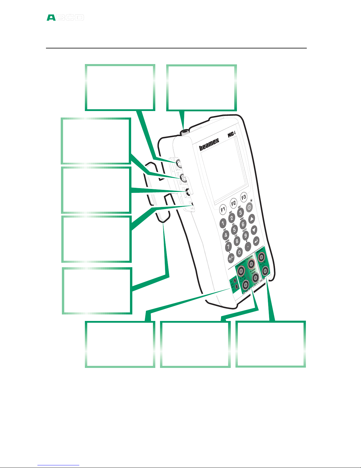
Connections
Ru b b e r c o v e r
t o p r o t e c t t h e
c o n n e c t o r s
O P T I O N
c o n n e c t o r f o r
f u t u r e n e e d s
U S B c o n n e c t o r
f o r c o m p u t e r
c o m m u n i c a t i o n
P O W E R
c o n n e c t o r
f o r c h a r g e r
I n t e r n a l
P r e s s u r e
M o d u l e
c o n n e c t o r
E X T c o n n e c t o r
f o r E x t e r n a l
P r e s s u r e
M o d u l e s
R T D M e a s . &
S i m u l a t i o n a n d
E l e c t r i c a l
G e n e r a t i o n
T h e r m o c o u p l e
M e a s u r e m e n t
& S i m u l a t i o n
E l e c t r i c a l
M e a s u r e m e n t s
a n d 2 4 V
S u p p l y
Note.
The picture above is of a MC4 with an internal pressure module.
Because the pressure module is an option Your MC4 may not
necessarily have it.

Connections
MC4 User Guide 7
Pressure Modules
Internal Gauge Type Pressure Module
MC4 may include one gauge type Internal Pressure Module.
The connector for the gauge type Internal Pressure module is
located in MC4's upper panel.
The allowed pressure media for gauge type internal pressure
modules is inert, non-to ic, non-e plosive media. Use of pressure
media classified as dangerous is prohibited.
For Beame 60° cone connector: To avoid damaging the calibrator,
use hand tightening only when connecting the pressure
measurement hose (ma . torque 5 Nm, appro . 3.6 lbf ft). If the use
of tools is required to secure the connection, apply the counterforce
with a spanner on the connector body's he agonal part.
Remember to be cautious when working with pressure and pressure
modules. See also chapters Safety on page 27 and Safety
Precautions and Warnings on page 28.
Internal Barometric Pressure Module
An Internal Barometric Pressure Module may also be included in
MC4. The Barometric Module may be installed together with a
Gauge Type Internal Pressure Module or it may be the only Internal
Pressure module installed in MC4.
The Internal Barometric Module measures the barometric pressure
through a connection found on the back side of MC4. Normally
nothing need to be connected to the barometric pressure module's
connector.
xternal Pressure Modules
MC4 has a connector for E ternal Pressure Modules (EXTs). The
connector is located on the left side of MC4.
If an E ternal Pressure Module is connected or removed, MC4
notices it automatically. More of pressure measurement in part B of
this manual.

MC4 Hardware
8 MC4 User Guide
Connectors on the Left Side of MC4
The left side of MC4 (front view) has four connectors as follows:
EXT E ternal Pressure Modules are discussed in chapter
xternal Pressure Modules on page 7 and in Part
B of this manual.
OPTION Reserved for future needs
USB For computer communication, e.g. when updating
the firmware and sending/receiving instrument data.
For USB driver information, see chapter PC
Communication on page 15.
POWER Charger connector (Battery eliminator when using
dry cells)
Warning!
There is no galvanic isolation between the connectors on the left
side as well as the internal pressure module connector.
Terminals
The lower part of the front panel has terminals for measuring,
generating and simulating signals.
Measuring capabilities of Measure section:
• Voltage,
• Current,
• Frequency,
• Pulse Counting and
• Switch state sensing.
Measuring capabilities of Temperature/Generate section:
• Low Voltage measurement using either the Low Voltage
connectors or the internal reference junction,
• T/C (thermocouple) measurement using either the internal
reference junction or the Low Voltage connectors,
• RTD measurement and
• Resistance measurement.
Table of contents
Other BEAMEX Test Equipment manuals


