Dings 70 Series User manual
BULLETINNO.BK4603
DATE8/94
4740WESTELECTRICAVENUEŸMILWAUKEE,WI53219Ÿ(414)6727830 ŸFAX(414)6725354
1
DIRACTBRAKES
70&80SERIES
INSTRUCTIONS
IMPORTANT
Readthisbulletincarefullybeforeinstallingoroperating
this brake. Failure to comply with these instructions
cancelsallwarrantiessincethesafetyoftheunitmaybe
endangered by improper installation or operating
procedures.
DESCRIPTION
Thisbrake is direct acting, electromagneticallyreleased
and spring set. It uses rotating and stationary disc
contact to supply positive braking action. It retains
quickreleaseandsettingcapabilitiesataltimes
Simplicity of design has reduced maintenance to an
absolute minimum. As with any electromechanical
equipment,however,periodicinspectionandadjustment
willassure optimumperformance. Asthe friction disc
wears, the magnet gap will increase. The magnet gap
should be checked periodically and adjusted when
necessary.
INSTALLATION
RefertoFigures3&5,Tables1,2&4
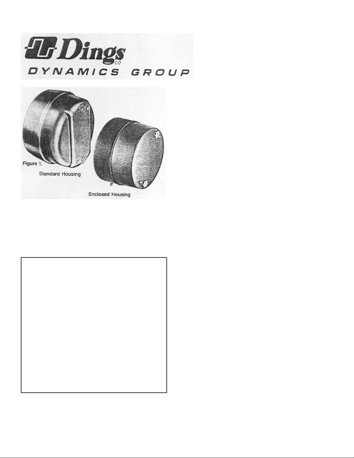
Figure1illustratesDiractbrakeswithastandardmanual
release.Thisreleaseconsistsoftworodsvisiblethruthe
cover. An optional release, the Mark II, has a single
leverasshowninFigure4.
1. Remove hub (1) from brakeand position on motor
shaft with key according to dimension “N”.
Stampedpartnumberonhubshouldfaceawayfrom
motor. Tighten hub set screws with 12 ft. lbs.
torque. On Mark II release models, motor shaft
shouldnotextendbeyondhub.
2. Removecoverscrews(24)andcover(23),plus“O”
ring (28) and gasket (32) on enclosed housing
models. OnMarkII models, moverelease lever to
horizontalposition.Removecover.
3. Place brake on motor, guiding discs on hub. On
MarkIImodels,thereleaselevershouldhangdown.
Thereleasemechanism isresetbygravity.
4. Boltbrake to motor “C” face withfoursockethead
cap screws. See Tables 1 and 2, and Figure 3 for
screwsize.
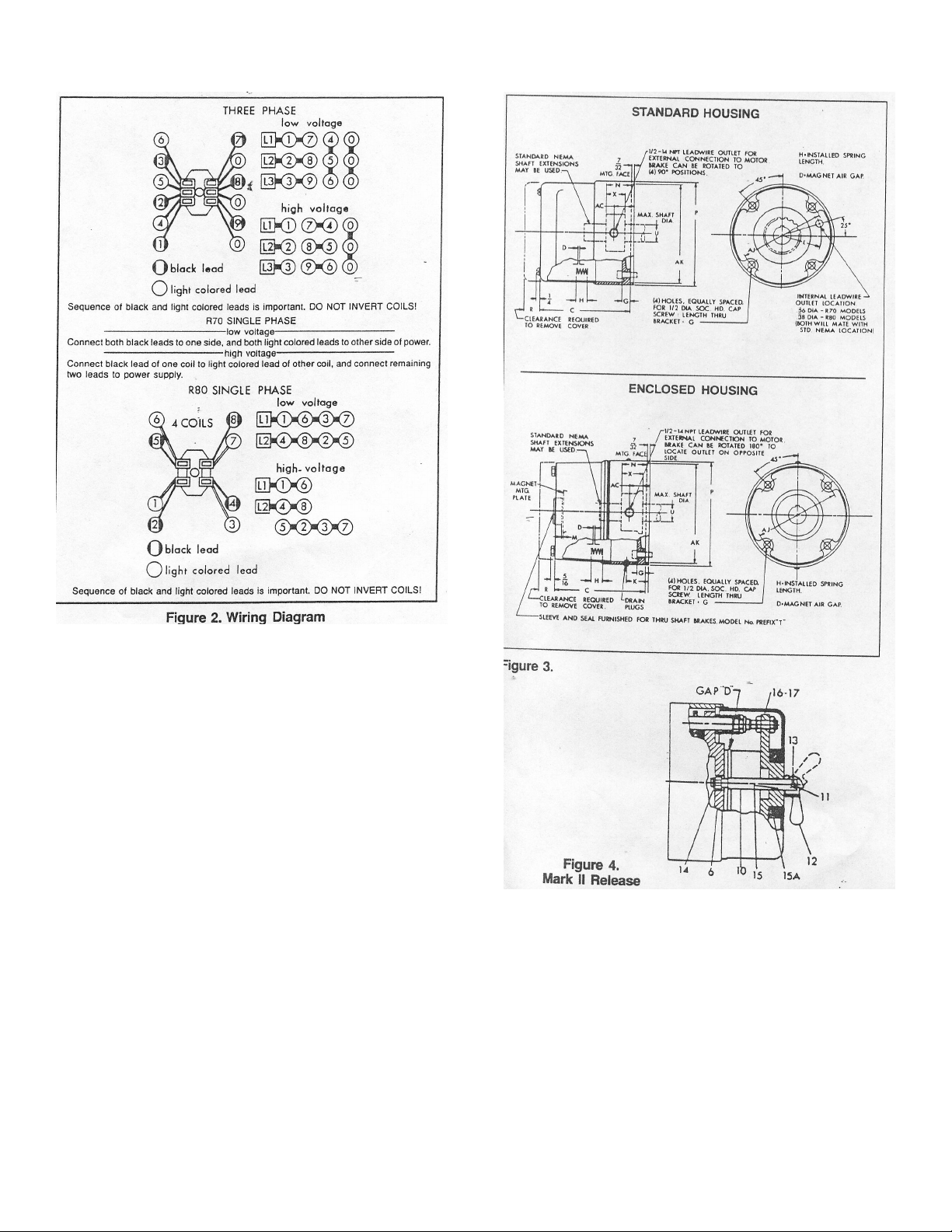
5. Connectcoilleadsperappropriatewiringdiagramin
Figure2andreplacecover.
WARNING
Brake performance and features must be carefully
matchedtotherequirementsoftheapplication.
Considerationmustbegiventotorquerequirements,
especially where an overhauling condition exists, as
well as thermal capacity, ambient temperature,
atmosphericexplosionhazards,typeofenclosureand
anyotherunusualconditions.
Improperselectionandinstallationofabrakeand/or
lack of maintenance may cause brake failure which
could result in damage to property and/or injury to
personnel.
If injury to personnel could be caused by brake
failure,additional means must beprovidedtoinsure
safetyofpersonnel.
Donotoperatemanualreleaseorenergizebrakecoil
beforeinstallation,inorderto preserveprealignment
ofrotatingdiscsforeaseofinstallation.
BULLETINNO.BK4603
DATE8/94
4740WESTELECTRICAVENUEŸMILWAUKEE,WI53219Ÿ(414)6727830 ŸFAX(414)6725354
2
MANUALRELEASEOPERATION
RefertoFigures4&5
To operate standard release (Figure 5), rotate two rods
(10)clockwiseuntilstopscrew(14)hitspin.Tooperate
Mark II release (Figure 4), push lever (12) to upward
position.Brakewillremaininrelease position untilrods
or lever are manually returned to original position, or
until electrical power is restored which automatically
resetsthebrake.
TORQUEADJUSTMENT
RefertoFigures3&5,Tables1or2
Brake is factory set for rated torque per spring length
“H”. To increase stopping time and lower torque, turn
two locknuts (9) counterclockwise, increasing
dimension “H”. Both spring lengths should be equal.
Donotdecreasespringlength “H”asthismaycausecoil
toburnout.

BULLETINNO.BK4603
DATE8/94
4740WESTELECTRICAVENUEŸMILWAUKEE,WI53219Ÿ(414)6727830 ŸFAX(414)6725354
3
MAINTENANCEANDSERVICE
WEARADJUSTMENT
Referto Figures3&5,Tables1or2
Magnet gap “D” increases as the rotating friction discs
wear. Whengapapproaches“D”max.,adjustgaptothe
“original setting” listed under “D” by turning nuts (21)
and (22). The “original setting” is also the minimum
allowed.
Too small a gap will not provide the proper running
clearance, and will cause excessive wear and
overheatingoftherotatingfrictiondisc.Themagnetgap
canvaryfrom“originalsetting”±.005betweencorners.
After setting gap, readjust torque spring length per
dimension “H”.
CAUTION:MAGNETGAPMUSTNOTEXCEED
“D”MAXIMUM.
FRICTIONDISCREPLACEMENT
RefertoFigures3,4&5.Tables1or2
Whenrotating frictiondisc(4)wearsdowntoa
thicknessof7/32”,replacedisc.
1. Removecoverscrews(24)andcover(23),plus“O”
ring(28)andgasket(32)onenclosedmodels.
2. Standardreleasemodel:Unhookloopoftorsion
springs(11)frompinsatrearofmagnetplate(16).
Removereleasestopscrews(14)washers(12)and
shims(13).SeeFigure5.MarkIIreleasemodel:
Removecotterpin(13)andreleaselever(12).See
Figure4.
3. Removeadjustinglocknuts(22)magnetassembly
(16),adjustingnuts(21),torque nuts(9),washers
(8),torquespring(7)andpressureplate(6).
4. Removefrictiondisc(4)andstationarydisc(5).
Replacewornfrictiondiscs.
5. Reassembleallpartsinreverseorder.Setspring
length “H”andmagnetgap“D”.Assemblemanual
release.Seefollowingparagraph.
MANUALRLEASEASSEMBLY
RefertoFigures3,4&5
Whenassemblingastandardmanualreleasemechanism
(Figure5),add onlyenoughshim washers(13)toobtain
properreleaseaction.Toomanyshim washerswill
preventautomaticresetwhenelectricalpowerisapplied.
Toofewwasherswillpreventthemotorshaftfrom
turningfreely.Replacesopscrews(14).Windeach
torsionspring(11)approximately ¼ turnandhook
springloopoverpin.
WhenassemblingaMarkIImanualreleasemechanism
(Figure4),attachlever(12)toreleaserod(1)withpin
(11)andcotterpins(13).Withlever(12)inraised
position,rotateleveruntilpressureplate(6)makes
contactwithmagnetassembly(16)closinggap“D”.
Lowertheleverandturn counterclockwise ¼ turn.The
levershouldnowhangdown,andifnot,removelever
andrelocateitascloseaspossibletodownpositionas
holesinrod(10)allow. The levermusthangdown
because resetisbygravity(verticalmountedbrakeshave
returnsprings).
Tocheckreleaseaction,raiselever.Motorshaftshould
turnfreely.Applypower.Levershouldreturntodown
position automatically. Ifshaftdoesnotturnfreely,turn
leverclockwise ¼ turn.Relocatelevertodownposition.
Ifleverdoesnotreturnautomatically,turnlever
counterclockwise ¼ turn.Relocatelevertodown
position.

BULLETINNO.BK4603
DATE8/94
4740WESTELECTRICAVENUEŸMILWAUKEE,WI53219Ÿ(414)6727830 ŸFAX(414)6725354
4

BULLETINNO.BK4603
DATE8/94
4740WESTELECTRICAVENUEŸMILWAUKEE,WI53219Ÿ(414)6727830 ŸFAX(414)6725354
5

BULLETINNO.BK4603
DATE8/94
4740WESTELECTRICAVENUEŸMILWAUKEE,WI53219Ÿ(414)6727830 ŸFAX(414)6725354
6
MAGNETCOILREPLACEMENT
Refertofigures5&6.
RemovemagnetassemblyasoutlinedunderFRICTIONDISC
REPLACEMENT.
Coils(18)areheldinplacewithepoxycement. Force coil offmagnet
mountingplateandremoveexcessepoxyfromallsurfaces.
Replacementcoilsshouldbeheldinplacewithnewepoxycement. The
epoxycementshouldbeheatresistantandshockresistant.Placean
insulatingwasher(19or19a)belowthecoils.Orderinsulatingwashers
whenorderingcoils.Aninsulation washercanbecuttosuitwhen
replacingonlyonecoilon amultiplecoilassembly.
Wheninstallingcoils,itisveryimportanttofollowEXACTLYthe
sequenceofblackandlightcoloredleadsasshowninwiringdiagram
(Figure2).Thebrakewillnotoperateproperlyunlesscoilsareallinthe
correctposition.

BULLETINNO.BK4603
DATE8/94
4740WESTELECTRICAVENUEŸMILWAUKEE,WI53219Ÿ(414)6727830 ŸFAX(414)6725354
7
TROUBLESHOOTING
A. IFBRAKEDOESNOTRELEASE:
1. Checkbrakevisuallyforbrokenordamaged
parts.
2. Checkforbroken leadwireorbadelectrical
connection.
3. Checkforcorrectvoltage.Linevoltagemust
correspondtothevoltageforwhichthebrake
coilsareconnected.Ifthelinevoltageismore
than10%belowthevoltageforwhichthebrake
coilsareconnected,themagnetwillnotpullin,
causingthecoilstoburnoutwithinminutes.If
thelinevoltageismorethan10%above the
voltageforwhichthebrakecoilsareconnected,
thecoilswilloverheatandburnout.
4. Checkforburnedoutcoils(coilsmaybecharred
orburned).
5. Checkforexcessivemagnetgap.(SeeWEAR
ADJUSTMENT.)
6. Checkforfailureofpowersupplytobrake.
B. IFBRAKEDOESNOTSTOP:
1. Checkbrakevisuallyforbrokenordamaged
parts.
2. Makecertainhubhasnotshiftedpositiononthe
motorshaftandthatallrotatingdiscsarefully
engagedonthehub.
3. Check thatthemanual release isinthenormal
position.
4. Check discwear.(SeeWEAR
ADJUSTMENT).
C. IFBRAKECHATTERSORHUMS:
1. Seethatmagnetfacesareclean.Toremovedirt,
insertacleansheetofpaperbetweenmagnet
facesandenergizebrake.Movepaperaround
betweenfacestodislodgedirt,thenremove
paper.
2. Checkforlowvoltage.Magnetwillnotpullin,
andcoilswillburnoutiflinevoltageisbeyond
10%below thevoltagethebrakecoilsare
connectedfor.
3. Seethatmagnetfacesareparallelwithin
tolerance.Readjustmagnetgapto “D”min.
(SeeWEARADJUSTMENT).
4. Checkifshadingcoil(2)iscracked,brokenor
outofposition (singlephaseonly).
D. IFMANUALRELEASEDOESNOTWORK:
1. Checkforbroken ordamagedparts.
2. Check returnspring(11).Brakewillnotreset
automaticallyifthisspringisbroken.
3. Checkmagnetgapwithbrakeinreleased
position.(SeeMANUALRELEASE
ASSEMBLY).
4. Checkquantityofshimwashers(13)under
releasestopscrews.(SeeMANUALRELEASE
ASSEMBLY.)
This manual suits for next models
29
Table of contents
Other Dings Industrial Equipment manuals


