Dini Argeo DGT4 User manual

+24Vdc GND
3
COM
4
IN1
5
IN2
6
RL1
7
RL2
8
COM I+ I- V+ V-
13
A(+)
14
B(-)
15
TX RX
16 17
GND
POWER INPUT RELAYS RS232
RS485
ANALOG
9 10 11 12
1 2
34
SIG-
33
SIG+
32
EXC-
31
EXC+
30
EXC-
29
SIG+
28
SIG-
27
EXC+
26
EXC+
25
SIG+
24 23 22 21 20 19
CELL1CELL2CELL4 CELL3
35
EXC- SIG- EXC+
EXC- SIG+
SIG-SEN- SEN+
18
www.diniargeo.com
DGT4
Digital weight transmitter with 4 channels
ENGLISHUSER MANUAL
For DGT4 with firmware release minimum 08.03


3
Optimized layout for A4 print.
TECH_MAN_ENG_DGT4_V8
Contents
Introduction 7
Transmitter installation 8
Installation requirements 8
Electrical precautions 9
Earthing of the system 11
Technical features 14
Load cell installation 15
Wiring diagrams 16
DGT4 16
DGT4AN 17
DGT4PB 18
DGT4ETHIP, DGT4ETHCAT, DGT4PRONET, DGT4MODTCP 19
DGT4CANOP 20
DGT4DEVNET 21
Display and function of the keys 22
Quick menu 22
Advanced programming menu 23
Access to the menu and saving the changes 23
Function of the keys in the menu 23
Block diagram of the menu 24
Mode of use of the DGT4 26
On / Off 27
Theoretical calibration 28
Dependent channels 28
Independent channels / transm 29
Calibration with sample weights 30
Dependent channels (with digital equalisation) 30
Independent channels / transm 32
Equalisation 34

4
Optimized layout for A4 print.
TECH_MAN_ENG_DGT4_V8
Manual calibration 35
Manual calibration 35
Quick zero calibration (pre-tare zeroing) 35
Filter and stability 36
Filter adjustment 36
Stability detection sensitivity 36
Display updating frequency 37
Gravity 37
Zeroing parameters 38
Auto-zeroing on ignition 38
Maximum percentage of manual zeroing 38
Zero tracking 38
Restoring zero 39
Semi-automatic zeroing 39
Tare functions and parameters 40
Tare mode 40
Semi-automatic tare 40
Predetermined tare 40
Clearing the tare 40
Alibi memory 41
Enabling the alibi memory 41
Saving a weighing operation in the alibi memory 41
Reading the alibi memory 42
Initialising the alibi memory 42
Use functions 43
High resolution 43
Peak detection 43
Converting units of measurement 43
Alibi memory 43
No function 43
Input configuration 44
Output configuration 45

5
Optimized layout for A4 print.
TECH_MAN_ENG_DGT4_V8
Analog output configuration 46
Serial communication configuration 48
Selection of the PC serial port 48
Configuration of the printer port (COM.PRN) 49
Transmission mode 49
Baud rate, parity, data bits, stop bits 50
Printer power on mode 50
CTS signal 50
Print language 50
Reactivation of printing 51
Configuration of the PC port (COM.PC) 51
Transmission mode 51
Baud rate, parity, data bits, stop bits 52
Communication protocols 53
Standard string 53
Extended string 53
Multi-scale string 54
Serial commands 55
Diagnostics 58
Cells / converter test 58
Firmware release 58
Serial number 58
Display 58
Keypad 58
Serial ports 59
CTS signal 59
Inputs 59
Outputs 59
Analog output (mod. DGT4XAN) 59
Programming the Setpoints 59
Restoring factory settings 60
Date and time setting 60
Alarms 61


7
Optimized layout for A4 print.
TECH_MAN_ENG_DGT4_V8
Dear Customer,
Thank you for purchasing a DINI ARGEO product.
This manual contains all the instructions for a correct installation and commissioning of the DGT4 4-channel digital weight transmitter.
While thanking you for purchasing this product, we would like to draw your attention to some aspects of this manual.
This booklet provides useful information for the correct operation and maintenance of the scale to which it refers; it is therefore essential
to pay the greatest attention to all those paragraphs that illustrate the simplest and safest way to operate.
It is recommended that you carefully follow the instructions for programming the weight transmitter; performing actions not indicated in
this manual could compromise the proper functioning of the scale.
The utmost care has been taken in compiling this manual, but reports of any inaccuracies are always welcome.
The instrument is covered by warranty and MUST NOT BE TAMPERED WITH BY THE USER under any circumstances.
Any attempt at repair or modification may expose the user to the danger of electric shock and voids any warranty conditions, relieving
the Manufacturer from all liability.
Any problem with the product must be reported to the manufacturer or to the retailer where it was purchased.
In any case, always TURN OFF THE POWER SUPPLY before any installation or repair operation.
Introduction

8
Optimized layout for A4 print.
TECH_MAN_ENG_DGT4_V8
Transmitter installation
Installation requirements
Observe the following conditions for correct installation of the transmitter and of the load receiver:
• Flat, level support surface.
• Stability and absence of vibrations.
• Absence of aggressive dusts and vapours.
• Absence of draughts.
• Make sure that the platform is levelled or that the load cells are evenly supported.
• Moderate temperature and humidity (15°C - 30°C and 40% - 70%).
• Do not install in an environment where there is a risk of explosion.
• All transmitter connections must be made in accordance with applicable regulations in the area and environment of installation.
Observe the electrical precautions listed in the section “Electrical precautions”.
• Ensure that it is correctly earthed, see the relevant section “Earthing of the system”.
• Do not perform welding when the load cells have already been installed.
• If necessary, use watertight sheaths and fittings to protect the load cell cables.
• Any junction boxes must be watertight.
• Anything not expressly described in this manual constitutes improper use of the equipment.

9
Optimized layout for A4 print.
TECH_MAN_ENG_DGT4_V8
Electrical precautions
• Use a regulated mains supply within ± 10% of the rated voltage.
• The electrical protections (fuses, etc.) are the responsibility of the installer.
• Observe the recommended minimum distances between cables of dierent categories (see table on page 10).
• The following cables must comply with the maximum permissible lengths (see table on page 10), they must be shielded and must
beinserted alone in metal conduits or pipes:
- the load cell extension cables;
- the signal amplifier cables;
- the cables for connecting the serial ports;
- the analog output cables.
• The cell or amplifier cables must have an independent input in the electrical panel. They must be connected (if possible) directly to
the terminal block of the transmitter without passing through the conduit with other cables.
• Fit “RC” filters:
- on the contactor coils;
- on the solenoid valve coils;
- on all devices that produce electrical interference.
• If condensation can occur inside the weight transmitter, it is advisable to keep the equipment powered at all times.
• Connections to load cells and any external device must be as short as possible.
• The cable ends (connectors, leads, terminals, etc.) must be installed correctly; the cable shielding must be kept intact until close to
the connection point.
• If the transmitter is placed inside an electrical panel, a shielded cable must also be used for the power supply.

10
Optimized layout for A4 print.
TECH_MAN_ENG_DGT4_V8
Category I Category II Category III Category IV
Distance
≥ 100 mm
≥ 200 mm
≥ 500 mm
≥ 100 mm
≥ 500 mm
≥ 500 mm
Classification
Fieldbus, LAN network
(PROFIBUS, Ethernet,
Devicenet...).
Shielded data cables
(RS232...).
Shielded cables for
analog digital signals
< 25 V (sensors, load
cells...).
Low voltage power sup-
ply cables (< 60 V).
Coaxial cables.
DC supply cables with
voltage > 60 V and <
400 V.
AC supply cables with
voltage > 25 V and <
400 V.
Power supply cables
with voltage > 400 V.
Telephone cables.
Any cable subject to
lightning danger.
Load cell RS232 RS485 Analog output
50 metres with
6 x 0.25 mm2cable;
100 metres with
6 x 0.5 mm2cable.
15 m with baud rate up
to19200.
1200 m with shielded 2 x
24 AWG twisted pair with
outer braid + aluminium
strip.
CURRENT:
100 metres with 2 x 0.25 mm2cable;
150 metres with 2 x 0.5 mm2cable;
300 metres with 2 x 1 mm2cable.
VOLTAGE:
50 metres with 2 x 0.25 mm2cable;
75 metres with 2 x 0.5 mm2cable;
150 metres with 2 x 1 mm2cable.
RECOMMENDED DISTANCES AND CABLE CLASSIFICATION
MAXIMUM ALLOWED LENGTHS

11
Optimized layout for A4 print.
i
TECH_MAN_ENG_DGT4_V8
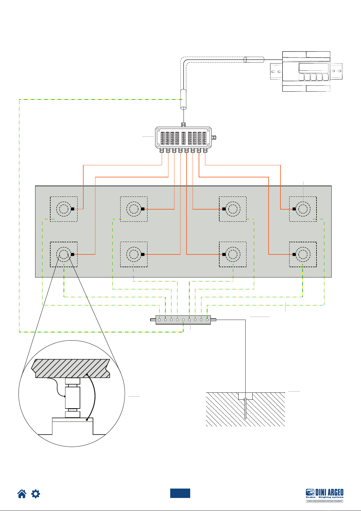
Earthing of the system
For correct earthing and optimal system operation, the load cells, junction box, if any, and weighing structure must be earthed.
LOAD CELLS AND JUNCTION BOX
The connection must be made by connecting the earth cables to the earth bar (cables that must have a cross-section of at least 16 mm2);
finally, connect the earth bar to the earth post with a cable having a cross-section of at least 50 mm2.
EXAMPLES:
• If the load cells are connected to the transmitter through a junction box, the cable shield from the transmitter and the cell cable shields
must be connected to the earth socket of the junction box (refer to the junction box manual) and the junction box must be earthed using
a copper cable with a cross-section of not less than 16 mm2.
• If the load cells are connected directly to the transmitter (without using the junction box), the cell cable shields must be connected to the
earthing point (or earth bar).
• If the weighing system involves large and/or outdoor structures (weighbridges, silos, etc.) and the distance between the junction box and
the weight transmitter is greater than 10 m, connect the cell cable shields to the earth socket in the junction box.
WEIGHING STRUCTURE
Earth the weighing structure and/or any unconnected structures (e.g. silos that release material onto the weighing structure) using cables
with a cross-section of not less than 16 mm2.
Also connect the upper part with the lower part of each cell by means of a copper braid with a cross-section not less than 16 mm2(refer
to the earthing examples on page 12 and page 13).
SERIAL CABLES AND CONNECTED INSTRUMENTS
Connect the serial cable shield to the earthing point (or earth bar) inside the panel. To avoid any undesired eects, the earth reference
ofthe connection cable, power supply and transmitter must be at the same potential.
GENERAL NOTES:
• All earth cables must be of suitable length, so as to obtain an overall resistance of the earthing system of less than 1 .
• If the weighing system involves large and/or outdoor structures (weighbridges, silos, etc.):
- the earth connection must be made by connecting the earth cables to an earth bar and the earth bar to the earth post
with a cable having a cross-section of not less than 50 mm2;
- the thickness of the cables must be greater (50 mm2instead of 16 mm2and 100 mm2instead of 50 mm2), because the
voltages at stake are greater (e.g. lightning);
- the earth post must be placed at a distance of at least 10 m from the structure.
• If the load receiver is more than 10 m from the transmitter, we recommend using the SENSE line and load cells equipped
with a (SENSE) compensation circuit.
12
Optimized layout for A4 print.
TECH_MAN_ENG_DGT4_V8
EXAMPLE OF EARTHING OF A WEIGHBRIDGE
Load cell bypass jumper
Weighbridge
Weight transmitter
Load cell
Earth cables
Ø 8 - sec. 50 mm2
Ø 11.3 - sec. 100 mm2
Earth post posi-
tioned under or
near the weigh-
bridge
Drilled copper plate positioned
on the side wall
Junction box placed on
the side wall of the pit
Weighbridge


14
Optimized layout for A4 print.
TECH_MAN_ENG_DGT4_V8
Technical features
POWER SUPPLY 12 - 24 Vdc LPS or with class 2 power supply.
MAXIMUM ABSORPTION
(without load cells)
DGT4: 100 mA at 12 V / 70 mA at 24 V (2 W);
DGT4AN: 185 mA at 12 V / 90 mA at 24 V (2.5 W);
DGT4 with fieldbus: 410 mA at 12 V; 220 mA at 24 V (5 W).
OPERATING TEMPERATURE From -15°C to +40°C.
DISPLAY DIVISIONS 10000e, 2 x 3000e for legal weighing, expandable up to 800,000 for internal use (with a
minimum cell signal of 1.6 mV/V).
SAMPLING SPEED Up to 400 conv. / sec.
MINIMUM VOLTAGE PER DIVISION 0.3 V (approved instrument); 0.03 V (non-approved instrument).
COUNTING RESOLUTION 1,500,000 points (with input signal 3 mV/V).
DISPLAY 6 digits, h 13 mm.
SIGNALS 6 status indicator LED lights.
KEYPAD 5 keys.
TARE FUNCTION Subtraction possible over the entire range.
LOAD CELL POWER SUPPLY 5 Vdc ± 5%, 120 mA (max 8 cells of 350 ).
LOAD CELL CONNECTION 6 wires (CELL1) with sense, 4 wires (CELLS 2, 3, 4).
CONNECTABLE CELLS Up to 8 350 cells.
CASE Made of plastic, suitable for DIN rail or wall mounting.
SERIAL OUTPUTS 1 RS485 bidirectional port;
1 configurable RS232 bidirectional port for connection to printer;
1 PROFIBUS port (DGT4PB* version);
2 ETHERNET ports (versions DGT4ETHIP*, DGT4MODTCP*, DGT4ETHCAT*, DGT4PR-
ONET*);
1 CANOPEN port (DGT4CANOP* version);
1 DEVICENET port (DGT4DEVNET* version).
* Fieldbus models are not equipped with port 485.
OUTPUTS / INPUTS 2 fotomosfet outputs NO or NC, configurable as programmable weight thresholds:
48 Vac 0.15 A max (or 60 Vdc 0.15 A max);
2 configurable inputs (optocouplers): 12 - 48 Vdc;
Input reading and output update time: 1 msec;
Opto-isolated analog output with 16 bits, optionally 4 - 20 mA, 0 - 5 Vdc or 0 - 10 Vdc (DG-
T4AN version). The maximum applicable resistance on the current output is 350 while
the minimum applicable resistance on the voltage output is 10 k.
LOAD CELL SENSITIVITY Maximum sensitivity of the connectable load cells: 6 mV/V.
FIELDBUS UPDATE RATES Up to 16 Hz.

15
Optimized layout for A4 print.
34
SIG-
33
SIG+
32
EXC-
31
EXC+
30
EXC-
29
SIG+
28
SIG-
27
EXC+
26
EXC+
25
SIG+
24 23 22 21 20 19
CELL1CELL2CELL4 CELL3
35
EXC- SIG- EXC+
EXC- SIG+
SIG-SEN- SEN+
18
+24Vdc GND
3
COM
4
IN1
5
IN2
6
RL1
7
RL2
8
COM
15
TX RX
16 17
GND
POWER INPUT RELAYS RS232
1 2
FIELDBUS
34
SIG-
33
SIG+
32
EXC-
31
EXC+
30
EXC-
29
SIG+
28
SIG-
27
EXC+
26
EXC+
25
SIG+
24 23 22 21 20 19
CELL1CELL2CELL4 CELL3
35
EXC- SIG- EXC+
EXC- SIG+
SIG-SEN- SEN+
18
+24Vdc GND
3
COM
4
IN1
5
IN2
6
RL1
7
RL2
8
COM
15
TX RX
16 17
GND
POWER INPUT RELAYS RS232
1 2
FIELDBUS
34
SIG-
33
SIG+
32
EXC-
31
EXC+
30
EXC-
29
SIG+
28
SIG-
27
EXC+
26
EXC+
25
SIG+
24 23 22 21 20 19
CELL1CELL2CELL4 CELL3
35
EXC- SIG- EXC+
EXC- SIG+
SIG-SEN- SEN+
18
34
SIG-
33
SIG+
32
EXC-
31
EXC+
30
EXC-
29
SIG+
28
SIG-
27
EXC+
26
EXC+
25
SIG+
24 23 22 21 20 19
CELL1CELL2CELL4 CELL3
35
EXC- SIG- EXC+
EXC- SIG+
SIG-SEN- SEN+
18
+24Vdc GND
3
COM
4
IN1
5
IN2
6
RL1
7
RL2
8
COM
15
TX RX
16 17
GND
POWER INPUT RELAYS RS232
1 2
FIELDBUS
34
SIG-
33
SIG+
32
EXC-
31
EXC+
30
EXC-
29
SIG+
28
SIG-
27
EXC+
26
EXC+
25
SIG+
24 23 22 21 20 19
CELL1CELL2CELL4 CELL3
35
EXC- SIG- EXC+
EXC- SIG+
SIG-SEN- SEN+
18
+24Vdc GND
3
COM
4
IN1
5
IN2
6
RL1
7
RL2
8
COM
15
TX RX
16 17
GND
POWER INPUT RELAYS RS232
1 2
FIELDBUS
34
SIG-
33
SIG+
32
EXC-
31
EXC+
30
EXC-
29
SIG+
28
SIG-
27
EXC+
26
EXC+
25
SIG+
24 23 22 21 20 19
CELL1CELL2CELL4 CELL3
35
EXC- SIG- EXC+
EXC- SIG+
SIG-SEN- SEN+
18
+24Vdc GND
3
COM
4
IN1
5
IN2
6
RL1
7
RL2
8
COM
15
TX RX
16 17
GND
POWER INPUT RELAYS RS232
1 2
FIELDBUS
34
SIG-
33
SIG+
32
EXC-
31
EXC+
30
EXC-
29
SIG+
28
SIG-
27
EXC+
26
EXC+
25
SIG+
24 23 22 21 20 19
CELL1CELL2CELL4 CELL3
35
EXC- SIG- EXC+
EXC- SIG+
SIG-SEN- SEN+
18
34
SIG-
33
SIG+
32
EXC-
31
EXC+
30
EXC-
29
SIG+
28
SIG-
27
EXC+
26
EXC+
25
SIG+
24 23 22 21 20 19
CELL1CELL2CELL4 CELL3
35
EXC- SIG- EXC+
EXC- SIG+
SIG-SEN- SEN+
18
+24Vdc GND
3
COM
4
IN1
5
IN2
6
RL1
7
RL2
8
COM
15
TX RX
16 17
GND
POWER INPUT RELAYS RS232
1 2
FIELDBUS
34
SIG-
33
SIG+
32
EXC-
31
EXC+
30
EXC-
29
SIG+
28
SIG-
27
EXC+
26
EXC+
25
SIG+
24 23 22 21 20 19
CELL1CELL2CELL4 CELL3
35
EXC- SIG- EXC+
EXC- SIG+
SIG-SEN- SEN+
18
+24Vdc GND
3
COM
4
IN1
5
IN2
6
RL1
7
RL2
8
COM
15
TX RX
16 17
GND
POWER INPUT RELAYS RS232
1 2
FIELDBUS
34
SIG-
33
SIG+
32
EXC-
31
EXC+
30
EXC-
29
SIG+
28
SIG-
27
EXC+
26
EXC+
25
SIG+
24 23 22 21 20 19
CELL1CELL2CELL4 CELL3
35
EXC- SIG- EXC+
EXC- SIG+
SIG-SEN- SEN+
18
+24Vdc GND
3
COM
4
IN1
5
IN2
6
RL1
7
RL2
8
COM
15
TX RX
16 17
GND
POWER INPUT RELAYS RS232
1 2
FIELDBUS
34
SIG-
33
SIG+
32
EXC-
31
EXC+
30
EXC-
29
SIG+
28
SIG-
27
EXC+
26
EXC+
25
SIG+
24 23 22 21 20 19
CELL1CELL2CELL4 CELL3
35
EXC- SIG- EXC+
EXC- SIG+
SIG-SEN- SEN+
18
34
SIG-
33
SIG+
32
EXC-
31
EXC+
30
EXC-
29
SIG+
28
SIG-
27
EXC+
26
EXC+
25
SIG+
24 23 22 21 20 19
CELL1CELL2CELL4 CELL3
35
EXC- SIG- EXC+
EXC- SIG+
SIG-SEN- SEN+
18
+24Vdc GND
3
COM
4
IN1
5
IN2
6
RL1
7
RL2
8
COM
15
TX RX
16 17
GND
POWER INPUT RELAYS RS232
1 2
FIELDBUS
34
SIG-
33
SIG+
32
EXC-
31
EXC+
30
EXC-
29
SIG+
28
SIG-
27
EXC+
26
EXC+
25
SIG+
24 23 22 21 20 19
CELL1CELL2CELL4 CELL3
35
EXC- SIG- EXC+
EXC- SIG+
SIG-SEN- SEN+
18
+24Vdc GND
3
COM
4
IN1
5
IN2
6
RL1
7
RL2
8
COM
15
TX RX
16 17
GND
POWER INPUT RELAYS RS232
1 2
FIELDBUS
34
SIG-
33
SIG+
32
EXC-
31
EXC+
30
EXC-
29
SIG+
28
SIG-
27
EXC+
26
EXC+
25
SIG+
24 23 22 21 20 19
CELL1CELL2CELL4 CELL3
35
EXC- SIG- EXC+
EXC- SIG+
SIG-SEN- SEN+
18
+24Vdc GND
3
COM
4
IN1
5
IN2
6
RL1
7
RL2
8
COM
15
TX RX
16 17
GND
POWER INPUT RELAYS RS232
1 2
FIELDBUS
34
SIG-
33
SIG+
32
EXC-
31
EXC+
30
EXC-
29
SIG+
28
SIG-
27
EXC+
26
EXC+
25
SIG+
24 23 22 21 20 19
CELL1CELL2CELL4 CELL3
35
EXC- SIG- EXC+
EXC- SIG+
SIG-SEN- SEN+
18
34
SIG-
33
SIG+
32
EXC-
31
EXC+
30
EXC-
29
SIG+
28
SIG-
27
EXC+
26
EXC+
25
SIG+
24 23 22 21 20 19
CELL1CELL2CELL4 CELL3
35
EXC- SIG- EXC+
EXC- SIG+
SIG-SEN- SEN+
18
+24Vdc GND
3
COM
4
IN1
5
IN2
6
RL1
7
RL2
8
COM
15
TX RX
16 17
GND
POWER INPUT RELAYS RS232
1 2
FIELDBUS
TECH_MAN_ENG_DGT4_V8
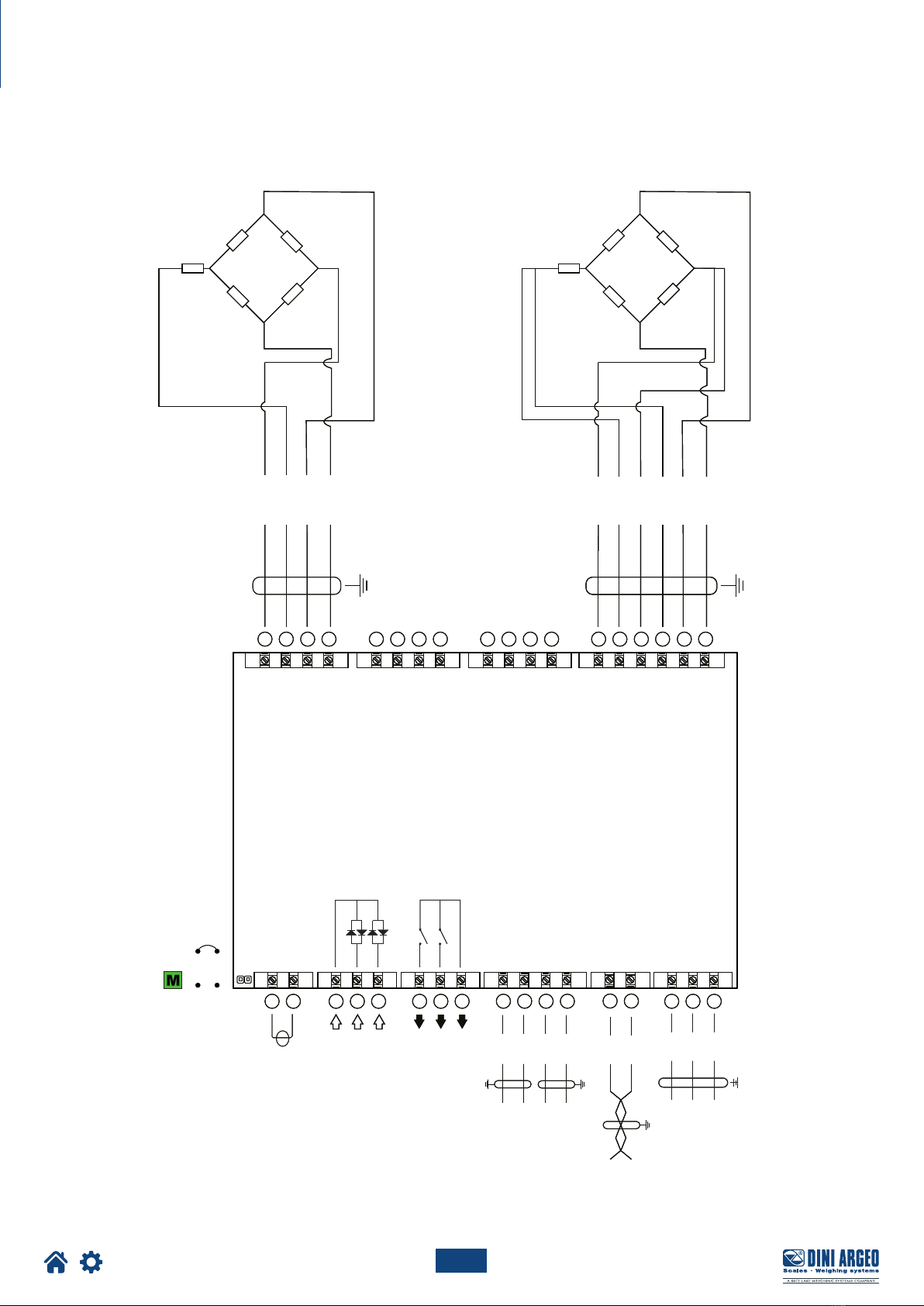
Load cell installation
After carrying out the instructions for the platform or load receiver, the shielded cable from the cell(s) must be properly connected to the
terminal block(s) of the transmitter (from CELL1 to CELL4; see section “Wiring diagrams”).
The transmitter has one channel (CELL1) for 6-wire connection to load cells (using the SENSE), while for the remaining channels (CELL2,
CELL3, CELL4) only 4-wire connection is allowed.
The SENSE allows you to compensate for any voltage drop on the section of cable connecting the transmitter to the load receiver.
It is especially useful when the distance between the transmitter and the load receiver is more than 10 metres.
4-WIRE CONNECTION
CELL2 / CELL3 / CELL4
6-WIRE CONNECTION
CELL2 / CELL3 / CELL4
6-WIRE CONNECTION
CELL1
4-WIRE CONNECTION
CELL1

16
Optimized layout for A4 print.
LOAD CELL 1
IN 2
IN 1
COM
COM
RL2
RL1
12 / 24 Vdc
15 16 176 7 83 4 51 2
33 3235 34 29 2831 30 25 2427 26 21 2023 22 19 18
E +
E -
+
+
-
-
S+ S-
SIG +
SIG -
REF +
REF -
EXC +
EXC -
LOAD CELL 2, 3, 4
LOAD CELL 4 LOAD CELL 3 LOAD CELL 2 LOAD CELL 1
E +
E -
+
+
-
-
S+ S-
SIG +
SIG -
EXC +
EXC -
GND
RX
TX
RS232
11 12 13 149 10
RS485
B(-)
A(+)
J1
+
-
TECH_MAN_ENG_DGT4_V8
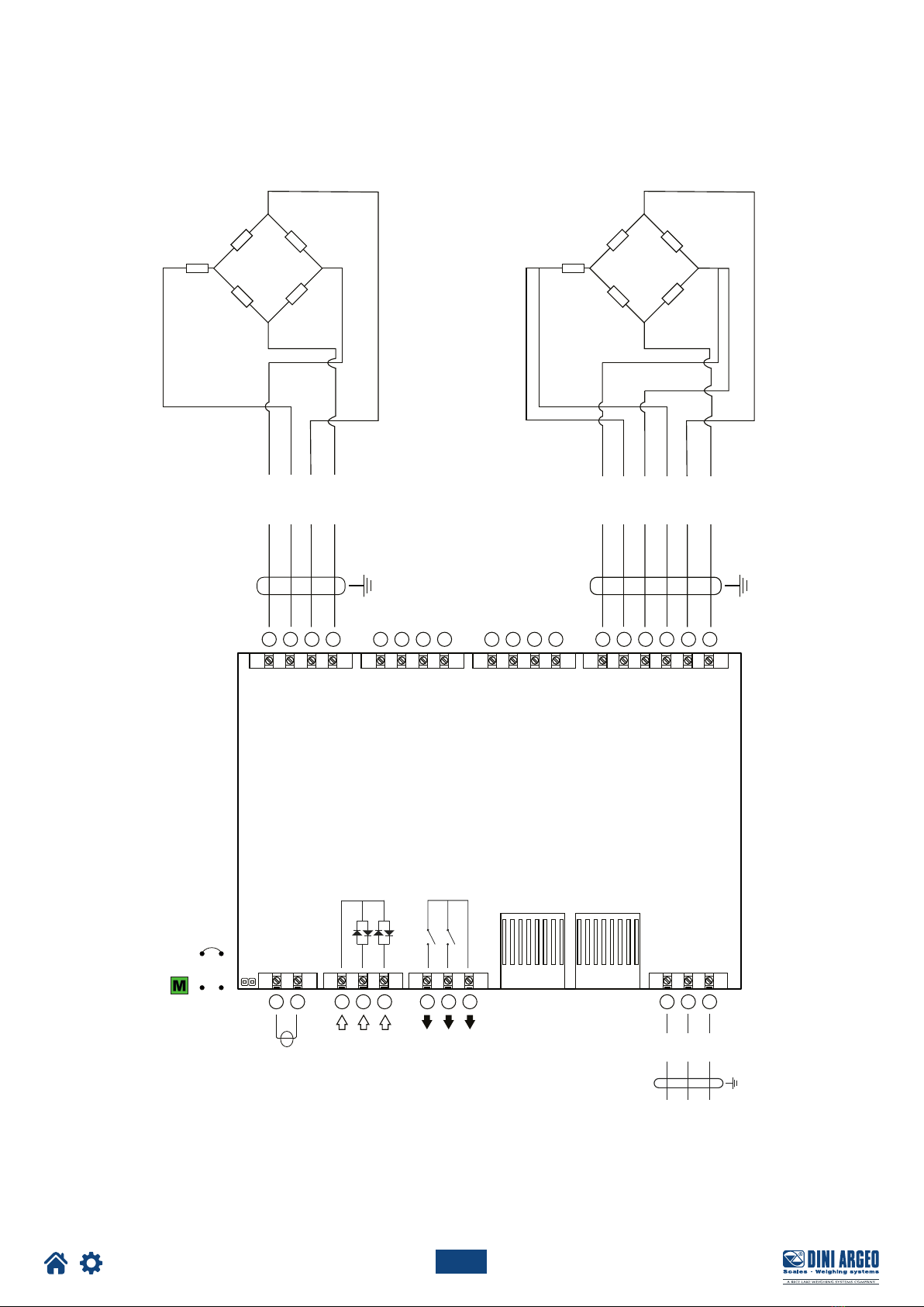
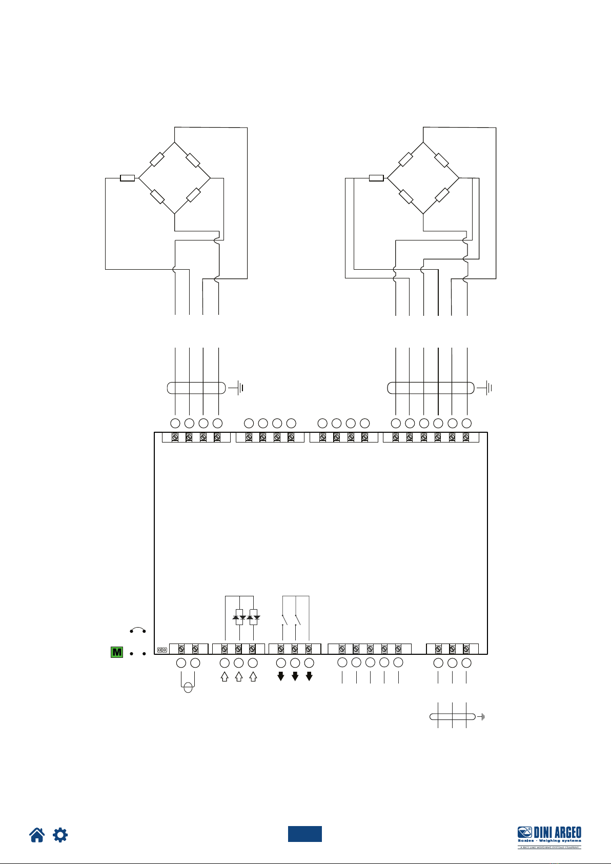
Wiring diagrams
DGT4
Internal use
17
Optimized layout for A4 print.
LOAD CELL 1
IN 2
IN 1
COM
COM
RL2
RL1
12 / 24 Vdc
15 16 176 7 83 4 51 2
33 3235 34 29 2831 30 25 2427 26 21 2023 22 19 18
E +
E -
+
+
-
-
S+ S-
SIG +
SIG -
REF +
REF -
EXC +
EXC -
LOAD CELL 2, 3, 4
LOAD CELL 4 LOAD CELL 3 LOAD CELL 2 LOAD CELL 1
E +
E -
+
+
-
-
S+ S-
SIG +
SIG -
EXC +
EXC -
GND
RX
TX
RS232
13 14
RS485
B(-)
A(+)
11 129 10
ANALOG
V-
V+
I-
I+
J1
+
-
TECH_MAN_ENG_DGT4_V8
LOAD CELL 1
IN 2
IN 1
COM
COM
RL2
RL1
12 / 24 Vdc
15 16 176 7 83 4 51 2
33 3235 34 29 2831 30 25 2427 26 21 2023 22 19 18
E +
E -
+
+
-
-
S+ S-
SIG +
SIG -
REF +
REF -
EXC +
EXC -
LOAD CELL 2, 3, 4
LOAD CELL 4 LOAD CELL 3 LOAD CELL 2 LOAD CELL 1
E +
E -
+
+
-
-
S+ S-
SIG +
SIG -
EXC +
EXC -
GND
RX
TX
RS232
13 14
RS485
B(-)
A(+)
11 129 10
ANALOG
V-
V+
I-
I+
J1
+
-
Internal use
DGT4AN

18
Optimized layout for A4 print.
LOAD CELL 1
IN 2
IN 1
COM
COM
RL2
RL1
12 / 24 Vdc
15 16 176 7 83 4 51 2
33 3235 34 29 2831 30 25 2427 26 21 2023 22 19 18
E +
E -
+
+
-
-
S+ S-
SIG +
SIG -
REF +
REF -
EXC +
EXC -
LOAD CELL 2, 3, 4
LOAD CELL 4 LOAD CELL 3 LOAD CELL 2 LOAD CELL 1
E +
E -
+
+
-
-
S+ S-
SIG +
SIG -
EXC +
EXC -
PROFIBUS
PORT
GND
RX
TX
RS232
J1
+
-
TECH_MAN_ENG_DGT4_V8
DGT4PB
Internal use
19
Optimized layout for A4 print.
LOAD CELL 1
+
-
IN 2
IN 1
COM
COM
RL2
RL1
12 / 24 Vdc
15 16 176 7 83 4 51 2
33 3235 34 29 2831 30 25 2427 26 21 2023 22 19 18
E +
E -
+
+
-
-
S+ S-
SIG +
SIG -
REF +
REF -
EXC +
EXC -
LOAD CELL 2, 3, 4
LOAD CELL 4 LOAD CELL 3 LOAD CELL 2 LOAD CELL 1
E +
E -
+
+
-
-
S+ S-
SIG +
SIG -
EXC +
EXC -
ETHERNET I/O PORT 1
ETHERNET I/O PORT 2
GND
RX
TX
RS232
J1
TECH_MAN_ENG_DGT4_V8
DGT4ETHIP, DGT4ETHCAT, DGT4PRONET, DGT4MODTCP
Internal use
20
Optimized layout for A4 print.
EDCBA
NC
CANL
NC
CANH
GND
LOAD CELL 1
IN 2
IN 1
COM
COM
RL2
RL1
12 / 24 Vdc
15 16 176 7 83 4 51 2
33 3235 34 29 2831 30 25 2427 26 21 2023 22 19 18
E +
E -
+
+
-
-
S+ S-
SIG +
SIG -
REF +
REF -
EXC +
EXC -
LOAD CELL 2, 3, 4
LOAD CELL 4 LOAD CELL 3 LOAD CELL 2 LOAD CELL 1
E +
E -
+
+
-
-
S+ S-
SIG +
SIG -
EXC +
EXC -
GND
RX
TX
RS232
J1
+
-
TECH_MAN_ENG_DGT4_V8
DGT4CANOP
Internal use
Other manuals for DGT4
1
Table of contents
Other Dini Argeo Transmitter manuals

Dini Argeo
Dini Argeo DGT4X User manual

Dini Argeo
Dini Argeo DGT1SX User manual

Dini Argeo
Dini Argeo DGT1S User manual

Dini Argeo
Dini Argeo DGT4X User manual

Dini Argeo
Dini Argeo DGT4XAN User manual

Dini Argeo
Dini Argeo DGT1SP User manual

Dini Argeo
Dini Argeo DGT1P User manual

Dini Argeo
Dini Argeo DGT1S User manual
Popular Transmitter manuals by other brands

Velleman
Velleman AVMOD17 quick guide

Zamel
Zamel RTN-01 Manual instruction

Dräger
Dräger Polytron 3000 Instructions for use

Magnetrol
Magnetrol Pulsar R86 manual

DB Elettronica Telecomunicazioni
DB Elettronica Telecomunicazioni CTX 5 user manual

Absolute Process Instruments
Absolute Process Instruments APD 1401 quick start guide


