Dini Argeo DGT4XAN User manual
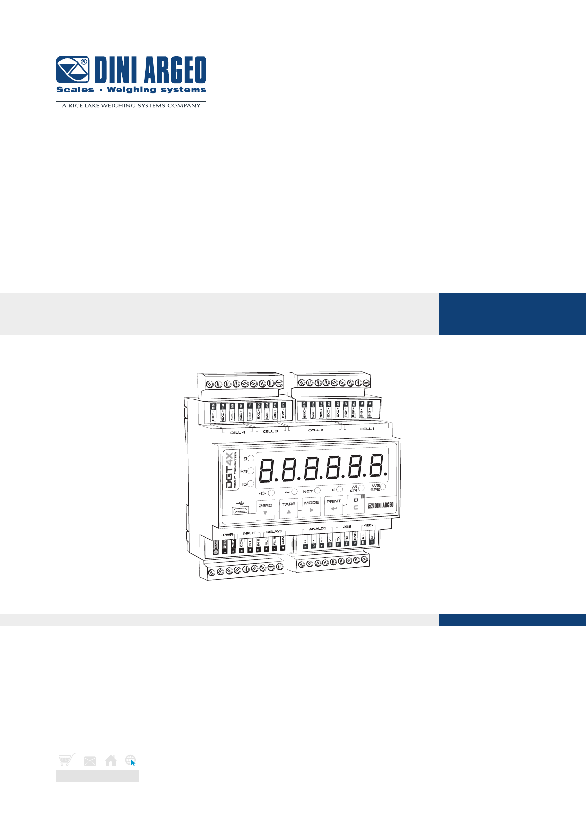
DGT4XAN
www.diniargeo.com
QUICK START GUIDE V1 ENGLISH
Digital weight Transmitter with 4 channels
2
LOAD CELL 1
IN 2
IN 1
COM
COM
RL2
RL1
13 14 156 7 83 4 5
33 3235 34 29 2831 30 25 2427 26 21 2023 22 19 18
E +
E -
+
+
-
-
S+ S-
SIG +
SIG -
REF +
REF -
EXC +
EXC -
LOAD CELL 2, 3, 4
LOAD CELL 4 LOAD CELL 3 LOAD CELL 2 LOAD CELL 1
E +
E -
+
+
-
-
S+ S-
SIG +
SIG -
EXC +
EXC -
GND
RX
TX
RS232
16 17
RS485
B(-)
A(+)
11 129 10
ANALOG
V-
V+
I-
I+
+-
12 / 24 Vdc
1 2
J1
REF -
REF +
JUMPER J1
QSG_ENG_DGT4XAN
INPUT:
12÷48 Vdc,
OUTPUT:
48Vac or 60Vdc,
0,5 A max
Max resistance on
current analog
output: 300 Ω
Min resistance on
voltage analog
output: 1 kΩ
CONSUMPTION:
4,5 W max.
For UL approved
models: equipment
to be powered by
12-24 Vdc LPS
or Class 2 power
source.
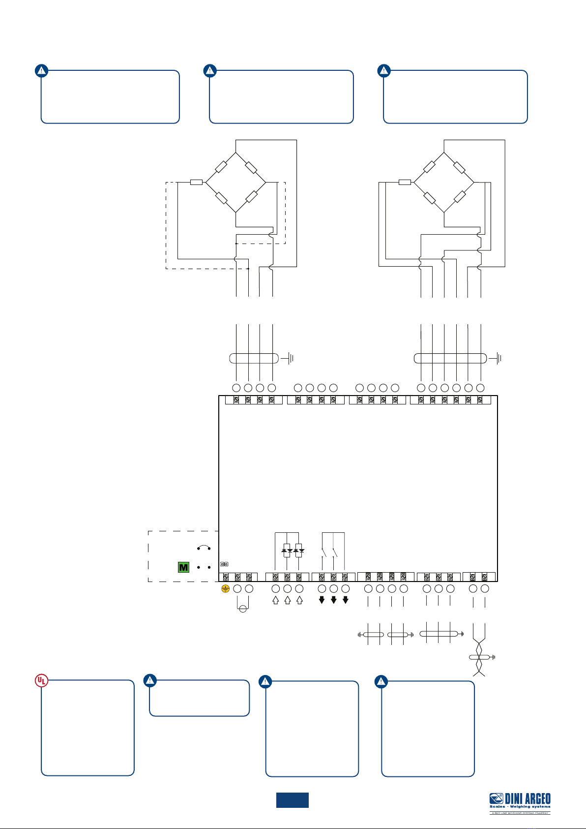
Load cells exitation: 5 V.
Load cells output: 6 mV/V max.
There’s a single SENSE circuit that
compensate all 4 load cells.
In LOAD CELL 2, 3, 4 connect:
SEN + to EXC +
SEN - to EXC -
1. Electrical scheme
Internal use

3
CELL 4 CELL 3 CELL 2 CELL 1
PWR INPUT 485RELAYS ANALOG232
g
kg
lb
NET
0~
FW1
SP1 W2
SP2
35
EXC -
EXC +34
SIG - 29
SIG + 28
SIG - 25
SIG + 24
EXC - 23
REF -
21
REF 20
SIG - 19
SIG + 18
26
EXC +
22
EXC +
+
EXC +30
EXC -
31
SIG + 32
SIG - 33
EXC -27
24Vdc
Earth
1
RL 1
6
RL 2
7
5
IN 1
4
COM
3
2
COM
8
GND
IN 2
I -
10
I +
9
GND
15
A +
16
14
TX
13
V -
12
11
B -
17
V +
RX
ZERO TARE MODE PRINT
g
kg
lb
NET
0
~
FW1
SP1 W2
SP2
QSG_ENG_DGT4XAN
2. Key function in configuration menu and in weighing mode
Configuration menu
Decreases digit / Scroll down.
Increases digit / Scroll up.
Enter the setup.
Selects digit to modify.
Enters a step / Confirms.
Clears / Exits a step (no save).
Weighing mode
Clears the displayed gross weight.
With short pressing: executes semiautomatic tare.
With long pressing: allows to enter known tare.
With long pressing: allows to switch between scales
(only in Mode 2 “ind.Ch”).
With short pressing: execute a data transmission on
the printer serial port.
With long pressing: Setpoint configuration.
ON/Standby of the instrument.
0
Weight on zero.
~
Unstable weight.
NET
A tare is active.
F
A function is active.
W1
SP1
Digital output 1 is active.
W2
SP2
Digital output 2 is active.
3. Indicator lights meaning
4
1
2
3
4
5
6
7
8
9
10
11
12
13
14 1
15 1
2
2
16
17
18
div.deC
TYPE
Cel.sen
span
i n P. 0 2
i n P. 0 1
oP
Cel.Cap
Chan
dead.ld
zero
0.Calib
adC.v
an.o
inPs
o . 0 1
o . 0 2
888888
CapaC
nChan
485
exCl.Ch
CloCk
QSG_ENG_DGT4XAN
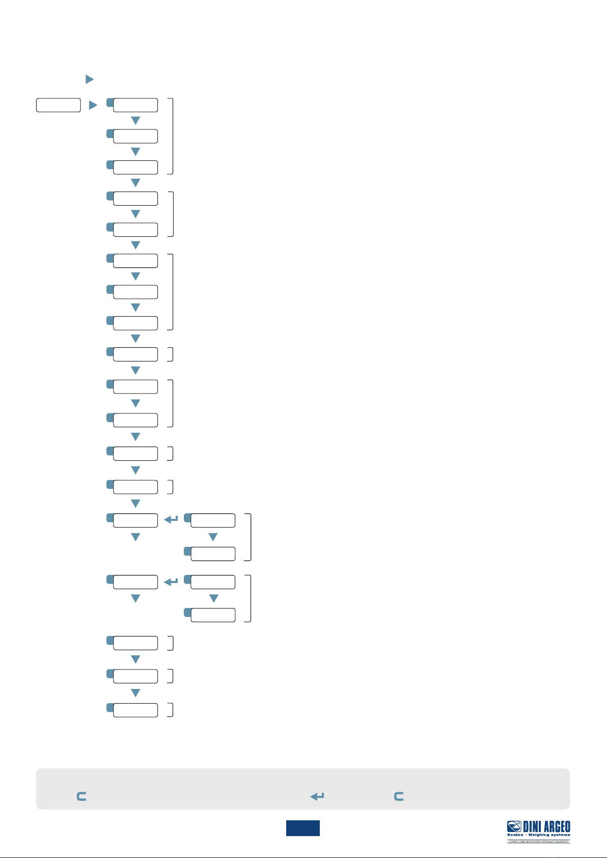
4. Configuration menu
1. Reboot the weight transmitter
2. Press the key when display shows the 888888 message:
Scale configuration: capacity, resolution and decimal point (ch. 6).
Theoretical calibration (ch. 7).
Zeroing of the deal load (pre-tare zeroing) (ch. 8).
Calibration with sample weight (ch. 9).
Load cells diagnostic (ch. 10).
Analog output (ch. 11).
Load cell exclusion (ch. 15).
Date and time setting (with optional card only).
RS485 port configuration (ch. 14).
Digital input configuration (ch. 12).
Digital output configuration (ch. 13).
Functioning mode (ch. 5).
HOW TO EXIT THE MENU AND STORE YOUR CONFIGURATION
1. Press key many times until save? message will appear; press to store or press to exit without storing.

5
1 1
2
2
3
TYPE
888888
CELL 4 CELL 3 CELL 2 CELL 1
PWR INPUT 485RELAYS ANALOG232
g
kg
lb
NET
0
~
FW1
SP1 W2
SP2
35
EXC -
EXC+34
SIG - 29
SIG + 28
SIG - 25
SIG + 24
EXC - 23
REF -
21
REF 20
SIG - 19
SIG + 18
26
EXC+
22
EXC+
+
EXC+30
EXC -
31
SIG + 32
SIG - 33
EXC -27
24Vdc
Earth
1
RL 1
6
RL 2
7
5
IN 1
4
COM
3
2
COM
8
GND
IN 2
I -
10
I +
9
GND
15
A +
16
14
TX
13
V -
12
11
B -
17
V +
RX
ZERO TARE MODE PRINT
g
kg
lb
NET
0
~
FW1
SP1 W2
SP2
dep.Ch
Type
nChan
Chan
ind.Ch
n.Chan
CHAN
= dep.Ch
= 2÷ 4
Type
Chan
n.Chan
= ind.Ch
= 1÷ 4
= 1÷ 4
CELL 4 CELL 3 CELL 2 CELL 1
PWR INPUT 485RELAYS ANALOG232
g
kg
lb
NET
0
~
FW1
SP1 W2
SP2
35
EXC -
EXC+34
SIG -
29
SIG +
28
SIG -
25
SIG +
24
EXC -
23
REF -
21
REF
20
SIG - 19
SIG + 18
26
EXC+
22
EXC+
+
EXC+30
EXC -
31
SIG +
32
SIG -
33
EXC -
27
24Vdc
Earth
1
RL 1
6
RL 2
7
5
IN 1
4
COM
3
2
COM
8
GND
IN 2
I -
10
I +
9
GND
15
A +
16
14
TX
13
V -
12
11
B -
17
V +
RX
ZERO TARE MODE PRINT
g
kg
lb
NET
0
~
FW1
SP1 W2
SP2
QSG_ENG_DGT4XAN
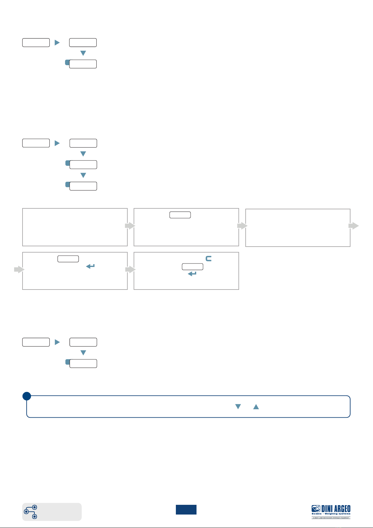
5. Functioning mode
Digital equalisation box mode.
Multi-scale mode.
Set the number of active channels.
Select the channel to be programmed (for ind,Ch mode only).
MODE 1 “DEP.CH”
MODE 2 “IND.CH”
Allows to connect directly the load cells, equalize them (if necessary) and transmit each load cell data and the total weight through Fieldbus.
Allows to manage up to 4 indipendent scales and transmit all data of each scale through Fieldbus.
not visible
Load cell 1
Scale 1
Load cell 3
Scale 3
Load cell 2
Scale 2
Load cell 4
Scale 4

6
6
7
8
888888
888888 div.deC
div.deC
...
Cel.Cap
div.deCCel.sen
dead.ld
CELL4 CELL 3 CELL2 CELL1
PWR INPUT 485RELAYS ANALOG232
g
kg
lb
NET
0
~
FW1
SP1 W2
SP2
35
EXC-
EXC+34
SIG- 29
SIG+ 28
SIG- 25
SIG+ 24
EXC- 23
REF-
21
REF 20
SIG- 19
SIG+ 18
26
EXC+
22
EXC+
+
EXC+30
EXC-
31
SIG+ 32
SIG- 33
EXC-27
24Vdc
Earth
1
RL1
6
RL2
7
5
IN1
4
COM
3
2
COM
8
GND
IN2
I-
10
I+
9
GND
15
A+
16
14
TX
13
V-
12
11
B-
17
V+
RX
ZERO TARE MODE PRINT
g
kg
lb
NET
0
~FW1
SP1 W2
SP2
CELL4 CELL 3 CELL2 CELL1
PWR INPUT 485RELAYS ANALOG232
g
kg
lb
NET
0
~
FW1
SP1 W2
SP2
35
EXC-
EXC+
34
SIG-
29
SIG+
28
SIG-
25
SIG+
24
EXC-
23
REF-
21
REF
20
SIG- 19
SIG+ 18
26
EXC+
22
EXC+
+
EXC+
30
EXC-
31
SIG+
32
SIG-
33
EXC-
27
24Vdc
Earth
1
RL1
6
RL2
7
5
IN1
4
COM
3
2
COM
8
GND
IN2
I-
10
I+
9
GND
15
A+
16
14
TX
13
V-
12
11
B-
17
V+
RX
ZERO TARE MODE PRINT
g
kg
lb
NET
0
~FW1
SP1 W2
SP2
6
7
div.deC
...
div.deC
div.deCCapaC
QSG_ENG_DGT4XAN
Complete menu
at page 4
6. Maximum scale capacity, increment and decimal point setting
Set the decimal point position and the minimum scale increment*1
( 0,001 - 0,002 - 0,005 - 0,01 - 0,02 - 0,05 - 0,1 - 0,2 - 0,5 - 1- 2- 5- 10 - 20 - 50 ).
Set the maximum scale capacity*2(max 999999 ).
Examples:
7. Theoretical calibration
Set the total load cells capacity (up to 999999).
Set the load cells sensitivity (up to 999999).
(mV/V cell1) + (mV/V cell2) + (mV/V cell3) + (mV/V cell4)
(mV/V cell1) + (mV/V cell2) + ... + (mV/V celln)
n
Insert in Cel.sen parameter, the load cells sensitivity
sum value:
For each scale to calibrate, insert in Cel.sen parameter the
average sensitivity value of the load cells:
Dead load weight (from -9999.9 to 99999.9).
*1Increment = the amount that the scale will increment by as weight is added or removed.
*2Maximum capacity = the maximum weight that can be measured using the scale you are creating.
1. Set div.deC and CapaC
(ch. 4).
2. Set in Cel.Cap the total load cells
capacity (sum of the nominal load cell
capacities).
3. Set in Cel.sen the theoretical signal
value of the load cells.
4. Enter in dead.ld step. The display
shows the theoretical dead load
value. Modify the value and/or confirm
with .
5. Save calibration (Press key many
times until save? message will
appear, then press to confirm).
For a 60000 kg scale, with 2 kg
increment:
div.deC = 2
CapaC = 60000
For a 10000 g scale, with 0,1 g increment:
div.deC = 0,1
CapaC = 10000,0
For a 3000 kg scale, with 0,05 kg
increment:
div.deC = 0,05
CapaC = 3000,00
MODE 1 “DEP.CH” MODE 2 “IND.CH”
7
12
11
10
9
888888
888888
888888
i
div.deC
div.deC
...
0.Calib
div.deC
div.deC
...
zero
Span
div.deC
...
adC.v
QSG_ENG_DGT4XAN
Complete menu
at page 4
8. Zeroing of the mechanic tare (pre-tare zeroing)
Zeroing of the pre-tare (or mechanical tare).
This functionality allows to zero the weigh of the scale structure (e.g. empty silo, conveyor, etc.) without changing the calibration in
memory.
9. Calibration with sample weight
Zero point acquisition.
1. Unload the scale. 2. Enter the zero step to adjust the
zero point.
5. Save adjustment (Press key
many times until save? message will
appear, then press to confirm).
Sample weight acquisition.
3. Load the scale with span weight.
4. Enter the span step, type the span
weight value and press to adjust.
10. Diagnostic of the load cell V/V
It allows to verify signal of each channel. It must be included into the range 0 to 3 mV/V.
Signal have to be stable and it have to increase by increasing the weight on the scale.
With more channels connected, it’s possible to scroll between channels with keys and .

8
13
2
1
4
3
1
2
1
2
3
3
5
7
6
888888 div.deC
...
an.o
div.deC
div.deC
div.deC
div.deC
div.deC
div.deC
mode
ao.ype
WG.min
Chan
ao Gro
0 10V
ao ne
0 5V
Cor.min
Cor.Max
wG.max
0 20ma
4 20ma
QSG_ENG_DGT4XAN
Complete menu
at page 4
11. Analog output
Analog output proportional to gross weight.
Analog output in voltage 0 ÷10 V.
Weight related to the analog output minumum value (deafult = 0 kg).
Channel selection (Visible only if ype = ind.Ch and nChan ≥ 2).
Weight related to the analog output maximum value. (default = CapaC kg).
Analog output in voltage 0 ÷10 V.
Minumum value fine adjustment.
Maximum value fine adjustment.
Analog output in current 0 ÷20 mA.
Analog output in current 4 ÷20 mA.
C. Use and keys to increase
or decrease the output value on the
multimeter.
By keeping the or key pushed,
the value will change faster.
Confirm with .
A. Enter the parameter Cor.0.B. Check the value on the multimeter
11.1 ANALOG OUTPUT FINE ADJUSTMENT
1. Connect a multimeter to pin 9 (+) and 10 (-) for the voltage analog output or 11 (+) and 12 (-) for the current analog output.
2. Follow the procedure:
Analog output proportional to net weight.
D. Repeat the operation from point “A”
for Cor.max parameter.
E. Save setting (Press key many
times until save? message will
appear, then press to confirm)

9
14 1
2 1
4
2
5
3
6
7
8
888888
C
none
are
mode
off
zero
prin
dis.key
div.deC
...
inps div.deCinp.01
inp.02
QSG_ENG_DGT4XAN
Complete menu
at page 4
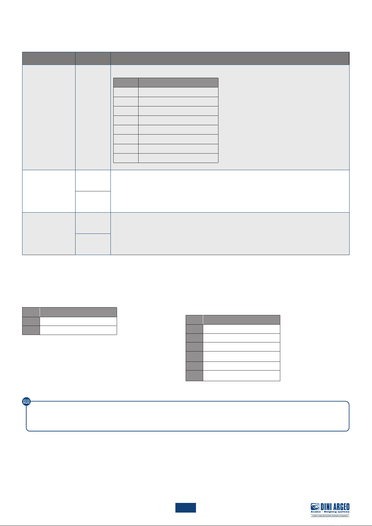
12. Input setting
See INP.02
Input disabled.
When input is active, transmitter keyboard is locked.
When input is active, transmitter reboots.
Emulation of key.
Emulation of key.
Emulation of key.
Emulation of key.
Emulation of key.
11.2 EXAMPLES
Impostazione dell’uscita analogica sul peso lordo a 0 10 V, for a
1000 kg scale:
• Connect a multimeter to pins 11 (+) e 12 (-).
• Select 0-10 V in the parameter Ao.ype.
• Select ao Gro in the parameter mode.
• Select the channel (if necessary) in the parameter Chan.
• Set the weight at 0 V in the parameter wG.min
(default = 0 kg).
• Set the weight at 10 V in the parameter wG.max
(default = 1000 kg).
• Correct, if necessary, the output values as shown
in chapter 11.2.
Impostazione dell’uscita analogica sul peso netto a 4 20 mA, for a
20000 kg scale:
• Connect a multimeter to pins 9 (+) e 10 (-).
• Select 4-20.ma in the parameter Ao.ype.
• Select ao ne in the parameter mode.
• Select the channel (if necessary) in the parameter Chan.
• Set the weight at 4 mA in the parameter wG.min
(default = 0 kg).
• Set the weight at 20 mA in the parameter wG.max
(default = 20000 kg).
• Correct, if necessary, the output values as shown
in chapter 11.2.
10
16 1
2
15 1
2 1
2 1
2
3
s.1 on
s.2 on
888888 div.deC
...
oUTPUT
no/nC
0 none
fnC
1 Gros
2 ne
div.deCo.01
o.02
888888 div.deC
...
485 div.deCse.add
bad
i
QSG_ENG_DGT4XAN
Complete menu
at page 4
13. Output setting
See o.02.
Setpoint on gross weight.
Setpoint on net weight.
Output disabled.
Normally open / normally close.
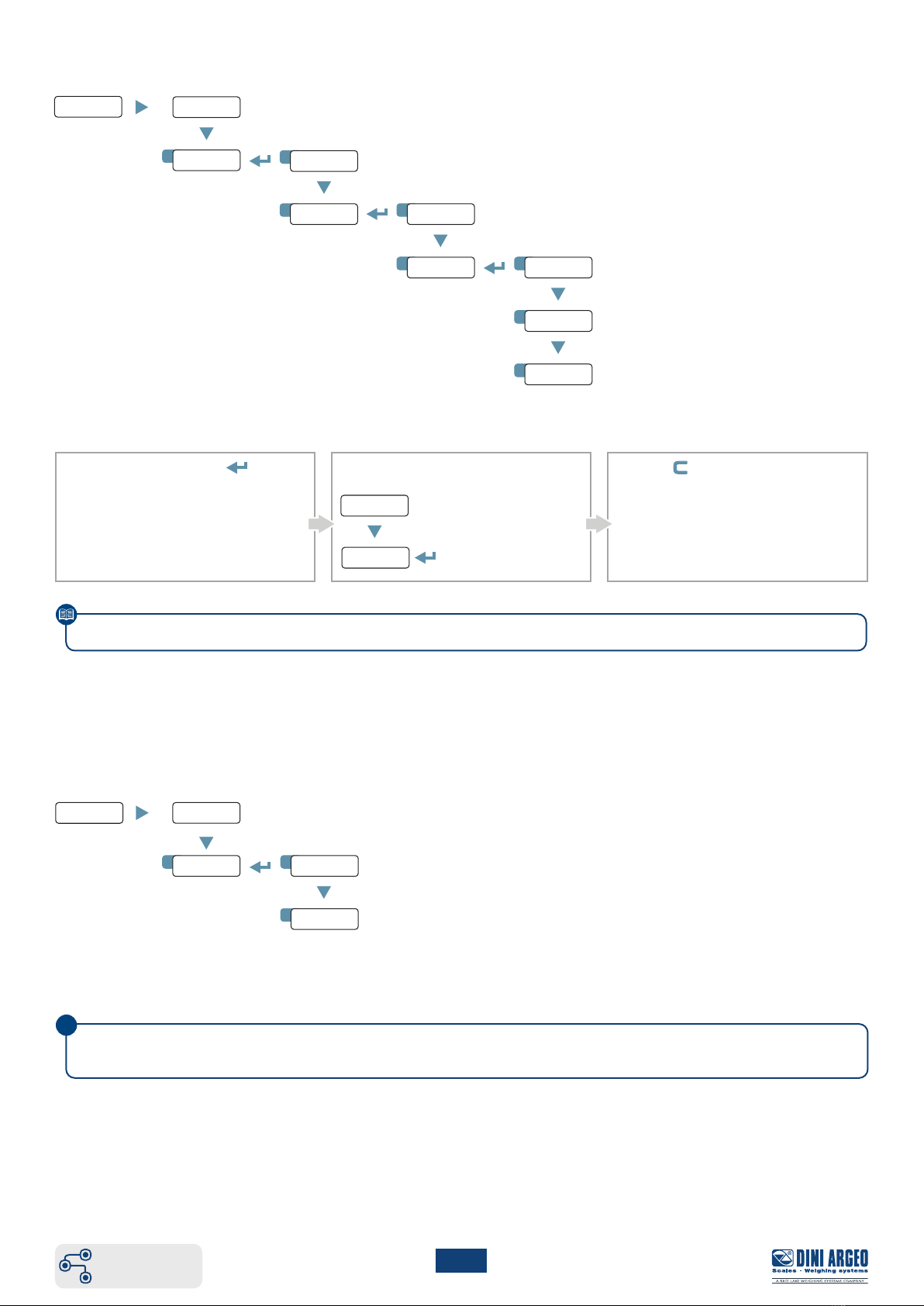
13.1 HOW TO PROGRAM SETPOINTS
1. In weighing mode, press
for 3 second.
2. Select the setpoint to modify:
Set the output 1
setpoint value.
Set the output 2
setpoint value.
3. Press key to store and exit
the menu.
Please refer to the complete technical manual for more information.
14. RS485 port
485 address (01 ÷ 98).
Baud rate (1200, 2400, 4800, 9600, 19200, 38400, 57600, 115200).
The RS485 port is configured by default to communicate in Modbus RTU (ch. 18).

11
17 1
2
3
4
5
888888 div.deC
...
exCl.Ch div.deCnone
Ch 1
Ch 2
Ch 3
Ch 4
QSG_ENG_DGT4XAN
Complete menu
at page 4
16. Programming errors
MESSAGE DESCRIPTION SOLUTION
preC. Calibration error First calibrate the zero point (zero), then proceed with the
sample weight acquisition (span) (ch. 9).
Err.pn Calibration error
Check the connection of the load cell. Check that the cell
signal is stable, valid and greater than that of the previously
acquired point.
Er 11 Calibration error Increase the calibration weight.
Er 12 Calibration error Check that the signal coming from the cell increases upon the
increasing of the weight loaded on the scale.
Er 37 Calibration error Repeat the calibration, checking that the capacity
and division have been correctly set.
Er 39 Instrument not configured Transmitter needs to be configurated.
C.e r. 36 Calibration error Check that the signal coming from the load cell is not negative.
C.e r. 37 Calibration error Check that the signal coming from the load cell is not negative.
Err.mo Weight unstable
Check in adC.v parameter that the signal is stable.
If the connection of the cells is with 4 wires, check that the sense
jumpers are inserted.
adC.err A/D converter error Converter failure. Reboot the instrument.
Cel.err Global load cell error Signal anomaly: check the load cells connection.
Er.Cel.1
...
Er.Cel.4
Load cell error Signal anomaly: check the indicated load cell connection.
15. Broken load cell exclusion (for dependent channel systems)
No channel excluded.
Channel 1 excluded.
Channel 2 excluded.
Channel 3 excluded.
Channel 4 excluded.
If a load cell is broken, it’s possible to temporarely exclude the channel where it is connected and continue to weigh, pending
replacement.
WARNING: this operation reduces the accuracy of the weighing system. We recommend use for liquid weighing or in applications
where the load is evenly distributed.
Visible only in DEP.Ch mode.

12
QSG_ENG_DGT4XAN
17. Modbus
17.1 MODBUS REGISTERS dep.CH /ind.ch (1 SCALE)
Data Register DESCRIPTION
Gross weight
30001
Gross Weight value.
30002
Net weight
30003
Net Weight value.
30004
Input status
register
30005
Bit 15
(msb)
Bit 14
Bit 13
Bit 12
Bit 11
Bit 10
Bit 9
Bit 8 (lsb)
Active channel.
Active channel.
No function.
No function.
No function.
No function.
Status of input n. 2.
Status of input n. 1.
Bit 7(msb)
Bit 6
Bit 5
Bit 4
Bit 3
Bit 2
Bit 1
Bit 0 (lsb)
1 = Scale unloaded (gross weight = 0).
Tare PT (1 = PT tare is active).
Tare (1 = Tare is active).
Overload condition (0 = No; 1 = Overload).
Underload condition (0 = No; 1 = Underload).
Weight Stability (0 = Unstable; 1 = Stable).
Gross Weight Polarity (0 = “+”; 1 = “-”).
Net Weight Polarity (0 = “+”; 1 = “-”).
Command status
register
30006
Last received command.
Bit 7(msb)
Bit 6
Bit 5
Bit 4
Bit 3
Bit 2
Bit 1
Bit 0 (lsb)
Last command result.
Last command result.
Last command result.
Last command result.
Counting of processed commands.
Counting of processed commands.
Counting of processed commands.
Counting of processed commands.
Output status
register
30007
No Function.
Bit 7(msb)
...
Bit 2
Bit 1
Bit 0(lsb)
No function.
...
No function.
Digital output 2 status (0 = OFF; 1 = ON).
Digital output 1 status (0 = OFF; 1 = ON).
µV Channel 1
30111 µV value of the channel 1.
µV Channel 2
30112 µV value of the channel 2.
µV Channel 3
30113 µV value of the channel 3.
µV Channel 4
30114 µV value of the channel 4.
Bit 15
Bit 14
Active Channel
0 0 Channel 1
0 1 Channel 2
1 0 Channel 3
1 1 Channel 4
This manual contains the main registers for reading data / sending commands.
Refer to the Modbus protocol manual for a complete list of available registers.

13
QSG_ENG_DGT4XAN
17.2 MODBUS REGISTERS ind.ch (4 SCALES)
Data Register DESCRIPTION
Status register
scale 1
40202
Bit 15
(msb)
...
Bit 8 (lsb)
No function.
Bit 7(msb)
Bit 6
Bit 5
Bit 4
Bit 3
Bit 2
Bit 1
Bit 0 (lsb)
Tare PT (1 = PT tare is active).
Tare (1 = Tare is active).
Net Weight Polarity (0 = “+”; 1 = “-”).
1 = Scale unloaded (gross weight = 0).
Overload condition (0 = No; 1 = overload).
Underload condition (0 = No; 1 = underload).
Stability (0 = “unstable”; 1 = “stable”).
Gross Weight Polarity (0 = “+”; 1= “-”).
Gross weight
scale 1
40203
Gross Weight of scale 1.
40204
Status register
scale 2
40205 Same as Status register scale 1.
Gross weight
scale 2
40206
Gross Weight of scale 2.
40207
Status register
scale 3
40208 Same as Status register scale 1.
Gross weight
scale 3
40209
Gross Weight of scale 3.
40210
Status register
scale 4
40211 Same as Status register scale 1.
Gross weight
scale 4
40212
Gross Weight of scale 4.
40213
Net weight
scale 1
40214
Net Weight of scale 1.
40215
Net weight
scale 2
40216
Net Weight of scale 2.
40217
Net weight
scale 3
40218
Net Weight of scale 3.
40219
Net weight
scale 4
40220
Net Weight of scale 4.
40221
This manual contains the main registers for reading data / sending commands.
Refer to the Modbus protocol manual for a complete list of available registers.
14
QSG_ENG_DGT4XAN
17.3 MODBUS REGISTERS FOR COMMAND SENDING
Data Register DESCRIPTION
Command
40001
Main available commands:
Value
Command
00 Hex
No command
01 Hex
Scale zeroing
02 Hex
Tare
03 Hex
Preset Tare
0A Hex
Setpoint 1 setting
0B Hex
Setpoint 2 setting
19 Hex
Digital output setting
22 Hex
Reboot the weight transmitter
Parameter 1
40002
First parameter of the command.
Parameter is always expressed in absolute mode (no decimals, no sign).
40003
Parameter 2
40004
Second parameter of the command.
Parameter is always expressed in absolute mode (no decimals, no sign).
40005
EXAMPLE 1
For zeroing the weight on the scale:
2. Set the command in byte 2
Byte
Value
100 Hex
201 Hex
EXAMPLE 2
For setting a preset tare of 1000 kg:
1. Set the tare value in parameter 1 (byte 3, 4, 5, 6)
2. Set the command in byte 2
Byte
Value
100 Hex
203 Hex
3(MSB) 00 Hex
400 Hex
503 Hex
6(LSB) E8 Hex
This manual contains the main registers for reading data / sending commands.
Refer to the Modbus protocol manual for a complete list of available registers.


The information in this document is approximate and can be subject to variations without prior notice by Dini Argeo, with respect of the norms in force. The ocial
technical data is available in the updated version on the www.diniargeo.com website or by contacting the Dini Argeo Customer Service.
Rev. 14.01.2020
HEAD OFFICE
Via Della Fisica, 20
41042 Spezzano di Fiorano, Modena - Italy
Tel. +39 0536 843418 - Fax +39 0536 843521
SERVICE ASSISTANCE
Via Dell’Elettronica, 15
41042 Spezzano di Fiorano, Modena - Italy
Tel. +39 0536 921784 - Fax +39 0536 926654
www.diniargeo.com
Authorized service center stamp
QSG_ENG_DGT4XAN
Table of contents
Other Dini Argeo Transmitter manuals

Dini Argeo
Dini Argeo DGT1S User manual

Dini Argeo
Dini Argeo DGT4X User manual

Dini Argeo
Dini Argeo DGT1SX User manual

Dini Argeo
Dini Argeo DGT1S User manual

Dini Argeo
Dini Argeo DGT4X User manual

Dini Argeo
Dini Argeo DGT1P User manual

Dini Argeo
Dini Argeo DGT1SP User manual

Dini Argeo
Dini Argeo DGT4 User manual
Popular Transmitter manuals by other brands


Trox Technik
Trox Technik MD-DPC-24 instructions

ABB
ABB Industrial IT enabled 2600T Series Operating instruction

WamBlee
WamBlee W420 Rescue-Me user manual

CALECTRO
CALECTRO eSENSE Manual for installation

Rotronic
Rotronic HygroClip IC-1-EX operating instructions

Thor Broadcast
Thor Broadcast F-RF-1550-Tx user manual