manuals.online logo
Brands
  1. Home
  2. •
  3. Brands
  4. •
  5. RMG
  6. •
  7. Controllers
  8. •
  9. RMG DFAWLC-044 User manual

RMG DFAWLC-044 User manual

DFAWLC-044 - Installation Manual
1
Version 1.0 - 09/20
Web: www.rmgautomation.com eMail: [email protected]m Contact: 044 - 43180017
Digital Fully Automatic Water Level Controller With Low/High
Voltage, Over Load, Dry Run protection and Timer - Tank Only
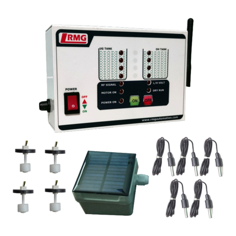
Digital Fully automatic water level controller will switch ON the motor when the water level in
the tank becomes low and will switch OFF the motor once the tank becomes full. This controller also has
the Voltage/Current /Dry Run Protection along with Timer function where it can be used as a cyclic
timer.
Picture1
Operating procedure:
Switch ON the controller with the help of the black button provided on the left side. Power ON
LED indication lights up.
Using the input keys (SET key, NEXT key and INC key), program the device as per your choice.
(Methods of programming the device is shared at the end for your reference).
Auto mode operation: In AUTO mode, motor will automatically switch ON when the water level
in the tank is low and automatically switch OFF when the tank becomes full.
Depending upon the water level in the tank, the level indication LED is ON.
When all the tank LED indication is OFF, the motor gets switched ON automatically. The motor
ON LED indication is ON. The tank starts filling and the corresponding LEDs starts lighting up.
When the T4 (higher level) LED indication goes ON, motor gets switched OFF. Motor ON LED
indication goes OFF.
Manual Mode: Helps to switch ON the motor manually. In this mode, the motor will be
constantly running. By changing it to AUTO mode, the above mentioned auto operation occurs.
This controller unit has a semi-automatic function (Manual ON and Auto OFF function). Just
keep the controller in MANUAL mode for the motor to get switched ON and then change it to
AUTO mode for Automatic OFF.
Dry Run Operation: When the motor is in ON condition, it checks the water flow in the inline
pipe of the tank. If there is no water flow for 1 minute, it switches OFF the motor preventing it
from Dry Run. Dry Run LED indication will be ON. This function occurs every one hour by default.
This reset time can be adjusted in Dry Run Time and the methods are explained below under
separate section.
Operation of L/H Voltage, O/U Load and Trip time: Motor will be in ON condition for the set
values. In any condition, the values goes low or high with set values, motor trips and will be OFF.
Based on the Trip time set, motor gets off. If any of these setting are not needed or To Disable
Operations –Set the Values as 0.
Timer Operation: This controller can be also used as a cyclic timer. ON time and OFF time can
be set as per below methods of programming and the motor will be ON for the set time and will
be OFF for the set time and the cycle repeats. In case if the tank is full, while the motor is ON, the
controller immediately switch off the motor and the display shows the voltage. Again motor
starts when tank is low.
The product is password protected and can be changed if required using the below methods.
DFAWLC-044 - Installation Manual
2
Version 1.0 - 09/20
Web: www.rmgautomation.com eMail: [email protected]m Contact: 044 - 43180017
Tools required for installation:
3 pair communication cable - Take a rough estimate of the cable length from the Water Level
Controller (WLC) location to the Over Head Tank (OHT)
Multi-strand 1.5 Sq.mm copper power cable –Cable length as per your requirement for power
connection.
Insulation tape, Line tester, Wire stripper, Simple hammer, Drill gun, Wooden Gattas, 2 Screws
for mounting the WLC on the wall.
Installation steps for Switch/MCB model
Sensor Connection
Step 1: Immerse the sensors as per the color coding given in the below picture.
Step 2: Dry Run Connection (If dry run connection is not possible for your tank, you must
join the DR and CN wires of the controller and use it as common wire).
Power Connection
Caution: Switch off the main power while doing the Power Connection steps.
Starter type connection:
Step 1: Connect Phase and neutral (230V) to red and black (paired) wire of the controller
respectively as shown in the Picture2.
Step 2: Remove the wire which connects the start and stop button terminals. Connect one wire
of blue pair and one wire of black pair to the start button where the wire was removed as shown in the
Picture 4.
Step 3: Connect the other wire of blue pair in parallel to the same side of the start button.
Step 4: Connect the other wire of the black pair to the stop button where the wire was removed
as shown in the Picture 2.
Switch type connection:
Step 1: Connect Phase and neutral (AC 230V) to red and black (paired) wire of the controller
respectively as shown in the Picture3.
Step 2: Connect Blue pair cable to the switch or MCB in parallel as shown in the Picture3.
In case of doubts please call 044 - 43180017 and for What’s App 9940594413 from
Monday to Saturday 10 am to 6 pm.
Working video link:
https://www.youtube.com/watch?v=UIw3ItC9DSw&feature=emb_logo
Starter connection:
Picture2
DFAWLC-044 - Installation Manual
3
Version 1.0 - 09/20
Web: www.rmgautomation.com eMail: [email protected]m Contact: 044 - 43180017
Switch/MCB Connection Diagram:
Picture3
Phase (Red +)
Neutral (Black -)
AC 230V
INPUT
Tank
Sump
L1-25%
CN Sensor
L2-50%
L3-75%
L4-100%
CN Sensor
L1-25%
L2-50%
Overflow Outlet
Water inline
T4 (Green)
INPUT
T3 (Yellow)
INPUT
T2 (Orange)
INPUT
T1 (Red)
INPUT
CN (Black)
INPUT
S3 (Grey)
INPUT
S1 (Blue)
INPUT
Blue Pair
INPUT
CN (Black)
INPUT
S2 (Violet)
INPUT
Power Connection
Connection
DR (Brown)
S4-100%
Sensor Connection
L3-75%
L4-100%
DFAWLC-044 - Installation Manual
4
Version 1.0 - 09/20
Web: www.rmgautomation.com eMail: [email protected]m Contact: 044 - 43180017
Programming Method:

Other RMG Controllers manuals

RMG GSM 3ST User manual

RMG

RMG GSM 3ST User manual

RMG AWLC-101 User manual

RMG

RMG AWLC-101 User manual

RMG DRTCC User manual

RMG

RMG DRTCC User manual

RMG 330 Guide

RMG

RMG 330 Guide

RMG RMG 610 Guide

RMG

RMG RMG 610 Guide

RMG 503 User manual

RMG

RMG 503 User manual

RMG GSM1SPAT User manual

RMG

RMG GSM1SPAT User manual

RMG EC 24 User manual

RMG

RMG EC 24 User manual

RMG WAWLCI -TS User manual

RMG

RMG WAWLCI -TS User manual

RMG 672 Guide

RMG

RMG 672 Guide

RMG 214 Guide

RMG

RMG 214 Guide

RMG AWFAWLC-044 User manual

RMG

RMG AWFAWLC-044 User manual

RMG AWLC-110-000 User manual

RMG

RMG AWLC-110-000 User manual

Popular Controllers manuals by other brands

Balmar Max Charge MC-624 Installation and operator's manual

Balmar

Balmar Max Charge MC-624 Installation and operator's manual

National Instruments myRIO-1950 instructions

National Instruments

National Instruments myRIO-1950 instructions

Thermo Ramsey Micro-Tech 3000 Series manual

Thermo

Thermo Ramsey Micro-Tech 3000 Series manual

Emerson Fisher 1051 instruction manual

Emerson

Emerson Fisher 1051 instruction manual

Hanna Instruments HI 8931 instruction manual

Hanna Instruments

Hanna Instruments HI 8931 instruction manual

Linak LA12 Connection diagram

Linak

Linak LA12 Connection diagram

Mitsubishi Electric LGF-100GX-E Handbook

Mitsubishi Electric

Mitsubishi Electric LGF-100GX-E Handbook

YASKAWA iQpump1000 user manual

YASKAWA

YASKAWA iQpump1000 user manual

CASTLE Mamba XLX2 quick start guide

CASTLE

CASTLE Mamba XLX2 quick start guide

NXP Semiconductors ISP1183 user manual

NXP Semiconductors

NXP Semiconductors ISP1183 user manual

Vykon JACE-700 install guide

Vykon

Vykon JACE-700 install guide

DSE 720 operating manual

DSE

DSE 720 operating manual

Toshiba TOSVERT VF-S15 series instruction manual

Toshiba

Toshiba TOSVERT VF-S15 series instruction manual

CG emotron TSA Series instruction manual

CG

CG emotron TSA Series instruction manual

Becker Centronic SunWindSet SWS42 Assembly and operating instructions

Becker

Becker Centronic SunWindSet SWS42 Assembly and operating instructions

Victron energy NV-48030 user manual

Victron energy

Victron energy NV-48030 user manual

Salus PC12HW quick start guide

Salus

Salus PC12HW quick start guide

Eaton WaveLinx series installation instructions

Eaton

Eaton WaveLinx series installation instructions

manuals.online logo
manuals.online logoBrands
  • About & Mission
  • Contact us
  • Privacy Policy
  • Terms and Conditions

Copyright 2025 Manuals.Online. All Rights Reserved.