manuals.online logo
Brands
  1. Home
  2. •
  3. Brands
  4. •
  5. DINUY
  6. •
  7. Controllers
  8. •
  9. DINUY KNK IT KNT 001 User manual

DINUY KNK IT KNT 001 User manual

EGB
ACTUADORDE PERSIANAS/TOLDOS1 CANAL Ó
ACTUADORDE CONMUTACIÓNDE 2 CANALES INDEPENDIENTES
ESPECIFICACIONES TÉCNICAS
DESCRIPCIÓN
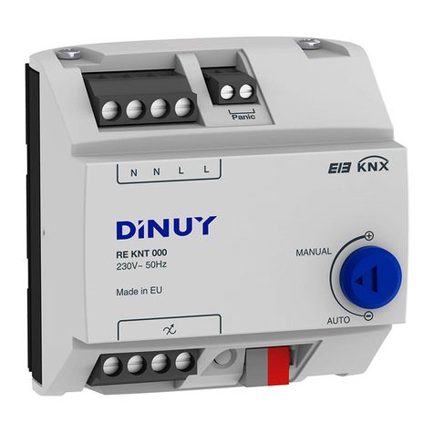
Se trata de unActuador de conmutación que puede funcionar como:
-Actuador de persianas/toldos de un canal de salida (Fig. 1).
-Actuador de conmutación de dos canales de salida independientes (Fig. 2).
Capacidad máxima de hasta 16Apor canal.
Dispone de 2 relés bi-estables.Incorpora la Unidad deAcoplamiento al Bus (BCU).
Formato modular, para su instalación sobre carril DIN.
Incorpora dos potenciómetros en el frontal (Ay B), uno para cada canal de salida
independiente. Permiten comprobar, manualmente, el funcionamiento correcto,
solamente, cuando trabaja comoActuador de Conmutación, sin necesidad
deconectar el Bus KNX:
· ON: Funcionamiento en ON permanente.
· OFF: Funcionamiento en OFF permanente.
·Auto: funcionamiento a través del Bus.
Programación y puesta en marcha mediante ETS4.
Dispone de terminal deconexión estándar (C).
IT KNT 001
Tensión Nominal 230V~ 50Hz
Alimentación desde KNX 21 ~ 32VCC (a través del Bus)
Conexión al Bus KNX Mediante terminal de conexión
Programación a través de ETS4
Medio KNX PT1
Canales de Salida 1 - Persianas ó 2 - Conmutación
Puesta en Marcha System Mode
Montaje Carril DIN 46277
Temperatura almacenamiento -30ºC ~ +70ºC
Grado protección IP20 (EN60529)
De acuerdo a las Directivas Seguridad 73/23/EEC
Comp. Electromagn. 204/108/EC
Certificación EIB/KNX
TensiónAislamiento 4KVCA (tensión alimentación/bus)
Carga 16Apor canal. 2 relés biestables.
Dimensiones 1 módulo, 17,5mm x 60mm
Temperatura funcionamiento -5ºC ~ +45ºC
De acuerdo a las Normas KNX Standard 2.0
EN60669-1, 2-1 y 2-3
1-CHANNELSHUTTERACTUATOROR
2-CHANNELSWITCHINGACTUATOR
DESCRIPTION
This device consists in a switching actuator which can operate as:
- 1-channel ShutterActuator (Fig. 1).
- 2-channel SwitchingActuator (Fig. 2).
Maximum output switching rating of up to 16Aper channel with
potential-freecontacts.
Integrated bus coupling unit (BCU).
Modular installation device for DIN 17,5mm rail.It incorporates two Potentiometers
(A& B), each one for each output channel. Itallows manual output control, for a
provisional operation, when it works asswitching actuator without being connected
to the KNX Bus:
· ON: Permanent Manual ON mode.
· OFF: Permanent Manual OFF mode.
·Auto: Bus operation.
Programmation and commissioning by ETS4.
It has a KNX standard connectingterminal (C).
TECHNICAL DATA
Nominal voltage 230V~ 50Hz
Supply from KNX bus 21 ~ 32VDC (via Bus)
Connection Connecting terminal
Commissioning ETS4
KNX Media TP1
Channels 1 - Shutter or 2 - Switches
Commissioning mode System Mode
Mounting DIN 46277 rail
Storage temperature -30ºC ~ +70ºC
Protection degree IP20 (EN60529)
Directives Low-voltage 73/23/EEC
EMC 204/108/EC
Marking EIB/KNX
Insulation voltage 4KVAC (bus/mains voltage)
Load 16Aper channel, 2 bistable relays
Dimensions 1 module, 17.5mm x 65mm
Working temperature -5ºC ~ +45ºC
According to the Standards KNX 2.0
EN60669-1, 2-1 & 2-3
A
C
B
D
E
GB E
DINUY S.A.
c/Auzolan Nº2
20303 Irún (Spain)
knx@dinuy.com
www.dinuy.com
INSTALACIÓNYCABLEADO
Siga los siguientes pasos para su instalación (Fig. 1 - Control Persiana/Toldo o
Fig. 2 - Control dos cargas independientes):
1) Conecte el Bus KNX al terminal de conexión (C).
2) Conecte la carga al actuador.
3)Active la alimentación de red.
4)Active la alimentación del Bus KNX.
PUESTAEN MARCHA
El funcionamiento del producto está condicionado a la parametrización realizada
mediante el ETS. Puede descargarse el software en nuestra página web:
www.dinuy.com.
Para la puesta en marcha del actuador, siga los siguientes pasos:
1) Programe la dirección física y parametrice el programa de aplicación desde el
ETS.
2) Presione el boton de programación (D). El LED de programación (E) se
encenderá en verde permanente y estará preparado para la programación a
través del programa de aplicación ETS. Esta programación tardará alrededor de
30 segundos y el LED parpadeará en rojo.
3) El LED de programación (E) se apaga, indicando que la programación se ha
realizado correctamente y el actuador está listo para funcionar.
TECLA (D)YLED (E) DE PROGRAMACIÓN
Además de posibilitar la puesta en marcha del dispositivo, permiten informar de un
problema de bloqueo del regulador, iluminandose el LED en rojo de forma
permanente. Esto sólo puede ser debido a una programación incorrecta desde el
ETS.
En caso de darse esta situación, es necesario Resetear el dispositivo, que consiste
tener pulsada la tecla de programación (D) durante 5 segundos. Además, tras este
paso, es necesario volver a programarlo mediante el ETS.
PRECAUCIONESYLIMITACIONES
· El suministro de red debe estar protegido de acuerdo a las normas vigentes.
· Los dispositivos deben ser instalados en ausencia de red y por personal
cualificado.
· Desconecte la tensión de red para manipular la carga, al sustituir lámparas
fundidas o al quitarlas o añadirlas.
· No exceda la carga máxima del aparato.
INSTALLATIONAND WIRING
Follow these steps for installation (Fig. 1 - Shutter Control or Fig. 2 - Switching
Control):
1) Connect the KNX bus to the connecting terminal (C).
2) Connect the lamps to the actuator.
3) Connect the mains voltage.
4) Connect the bus voltage.
COMMISSIONING
Performance of the product is subject to the parameterization made by ETS. You
can download the application software from our website:
www.dinuy.com.
For the commissioning of the actuator, follow these steps:
1) Allocate the physical adress and parameterize the application software from the
ETS.
2) Press the programming key (D). The green programming LED (E) will be
on and the actuator will be ready for loading the application software into the
device. This programming will take around 30sec and the red programming LED
(E) will go on.
3) The programming LED (E) will go off: the application has been loaded
successfully and the dimmer is ready for working.
PROGRAMMING KEY(D)AND LED (E)
In addition to enabling to set the actuator into operation, it is also useful to inform
about a blocking problem of the dimmer, lighting permanently red. This can only
be due to incorrect programming from ETS.
In case of this problem, it would be necessary to reset the device, pressing the
programming key (D) for 5sec. More over, after this step, it should be
reprogrammed by the ETS.
CAUTIONSAND LIMITATIONS
· The mains supply must be protected according to existing rules.
· Electrical equipment must be installed and fitted by qualified electricians only and
without power supply.
· Disconnect the mains to handle the load, replacing burned-out lightbulbs,
removing or adding new ones.
· Do not exceed the maximum load of the device.
IT KNT 001
Bus KNX
IT KNT 001
Bus KNX
M
5 6
3 4
1 2
5 6
3 4
1 2
+
-
+
-
Fig. 1
L
N
230V~ 50Hz
Fig. 2
L
N
230V~ 50Hz

Other DINUY Controllers manuals

DINUY PE K5X 002 User manual

DINUY

DINUY PE K5X 002 User manual

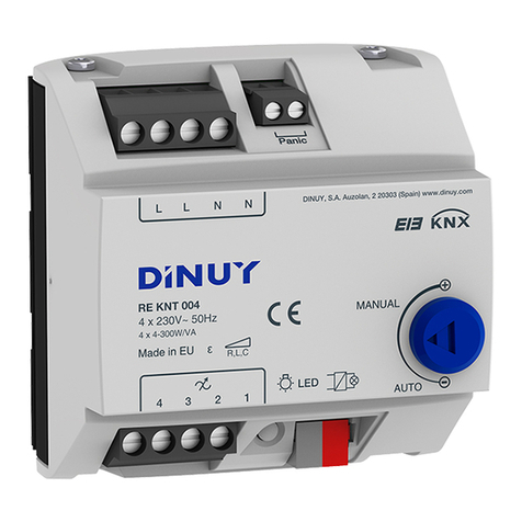
DINUY RE KNT 004 User manual

DINUY

DINUY RE KNT 004 User manual

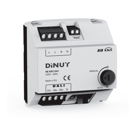
DINUY KNX RE KNT DA1 User manual

DINUY

DINUY KNX RE KNT DA1 User manual

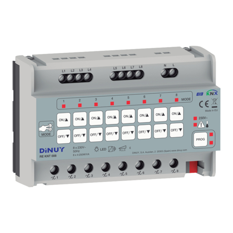
DINUY KNX RE KNT 008 User manual

DINUY

DINUY KNX RE KNT 008 User manual

DINUY RE KNT 000 User manual

DINUY

DINUY RE KNT 000 User manual

Popular Controllers manuals by other brands

Siemens LMV60.110A2 installation guide

Siemens

Siemens LMV60.110A2 installation guide

Eurotherm 7000 Series user manual

Eurotherm

Eurotherm 7000 Series user manual

Danfoss ADAP-KOOL AK-PC 781 user guide

Danfoss

Danfoss ADAP-KOOL AK-PC 781 user guide

Hach CD500 user manual

Hach

Hach CD500 user manual

digitalview AL-1280 instructions

digitalview

digitalview AL-1280 instructions

Juniper C2000 Hardware guide

Juniper

Juniper C2000 Hardware guide

Watts LF223 series installation instructions

Watts

Watts LF223 series installation instructions

TEUCER LR-4RGBCCT quick start guide

TEUCER

TEUCER LR-4RGBCCT quick start guide

SRS Labs RMC12, RMC8 instruction manual

SRS Labs

SRS Labs RMC12, RMC8 instruction manual

ESAB PEH A2 instruction manual

ESAB

ESAB PEH A2 instruction manual

Omron SYSMAC CS1G Operation manual

Omron

Omron SYSMAC CS1G Operation manual

Pentair SOLARTOUCH 521606 installation guide

Pentair

Pentair SOLARTOUCH 521606 installation guide

Quantum SDLC 2.7 release note

Quantum

Quantum SDLC 2.7 release note

Electro-Voice PWS-4 owner's manual

Electro-Voice

Electro-Voice PWS-4 owner's manual

PS Automation PSF-M operating instructions

PS Automation

PS Automation PSF-M operating instructions

Sunricher SR-ZV9003T3-RGBW-US Installation

Sunricher

Sunricher SR-ZV9003T3-RGBW-US Installation

Omron SYSMAC CJ1W-EIP21 Operation manuals

Omron

Omron SYSMAC CJ1W-EIP21 Operation manuals

M2M C350 pro Technical manual

M2M

M2M C350 pro Technical manual

manuals.online logo
manuals.online logoBrands
  • About & Mission
  • Contact us
  • Privacy Policy
  • Terms and Conditions

Copyright 2025 Manuals.Online. All Rights Reserved.