Diodes AL8400QEV1 User manual
September 2018 www.diodes.com
© Diodes Incorporated, 2018
AL8400QEV1 EVALUATION BOARD USER GUIDE
DESCRIPTION
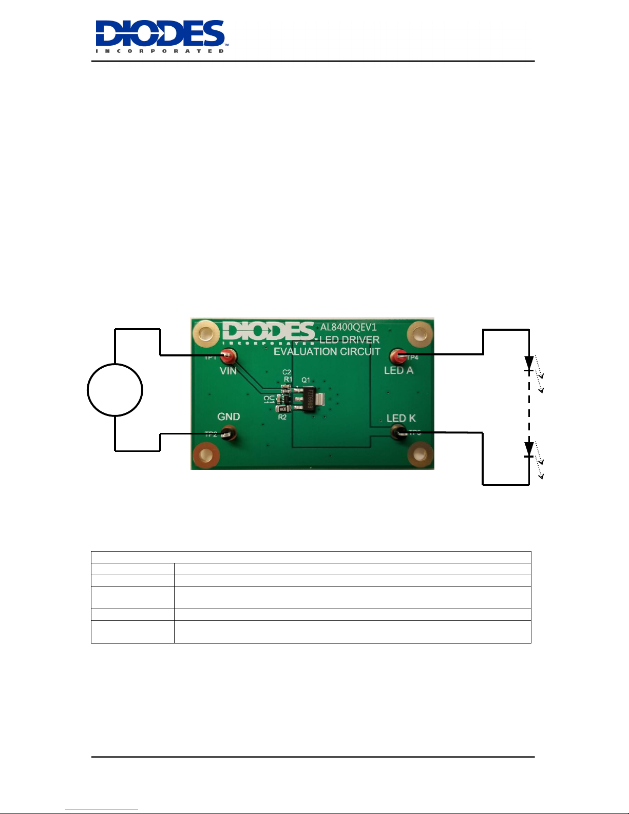
The AL8400QEV1, Figure 1, is a double sided evaluation board for the AL8400Q linear LED driver.
The evaluation board is preset to drive 150mA through the LED string, the maximum number of which
depends on their total forward voltage drop.
The operating voltage is between 4 and 18 volts, depending on the LED string to be driven. Higher
voltages for longer LED strings can be used by tapping off the board Vin from an intermediate point in
the LED string.
Note: The evaluation board does not have reverse supply protection.
The sense resistor R2 of 300mΩsets the LEDs nominal current at 150mA.
Figure 1: AL8400QEV1 evaluation board and connection diagram
AL8400QEV1 Connection Point Definition
Name
Description
Vin
Positive supply voltage. 4 to 18V
GND
Supply Ground (0V)
LED A
LED A connects to the external LED string anode
LED K
LED K connects to the external LED string cathode
4-18VDC
LEDs
V
V

AL8400QEV1
September 2018 www.diodes.com
© Diodes Incorporated 2018
2
AL8400Q DEVICE DESCRIPTION
The AL8400Q is a 5-terminal adjustable Linear LED driver controller offering excellent temperature
stability and output handling capability. The AL8400Q simplifies the design of linear and isolated LED
drivers. With its low 0.2V FB pin, it controls the regulation of LED current with minimal power
dissipation when compared to traditional linear LED drivers. This makes it ideal for medium to high
current LED driving.
AL8400Q DEVICE FEATURES
Low reference voltage (VFB = 0.2V)
-40 to 125ºC temperature range
3% Reference voltage tolerance at
25°C
Low temperature drift
0.2V to 18V open-collector output
High power supply rejection
(>45dB at 300kHz)
DEVICE APPLICATIONS
Isolated offline LED converters
Linear LED driver
LED signs
Instrumentation illumination
AL8400Q Device Packages, Pin and Definitions
AL8400Q
2
1
3 4
5
GND
E1
VCC FB
OUT
SOT353 pack
AL8400Q Device Pin Definition
Name
Pin No
Description
E1
1
Emitter connection. Connect to GND.
GND
2
Analog Ground: Ground return for reference and amplifier. Connect
to E1.
VCC
3
Supply Input. Connect a 0.47μF ceramic capacitor close to the device
from VCC to GND.
FB
4
Feedback Input. Regulates to 200mV nominal.
OUT
5
Output. Connect a capacitor close to device between OUT and GND.
ORDERING INFORMATION
EVALBOARD ORDER
NUMBER
AL8400QEV1
Please note: Evaluation boards are subject to
availability and qualified sales leads.
DEVICE ORDER NUMBER
AL8400QSE-7

AL8400QEV1
September 2018 www.diodes.com
© Diodes Incorporated 2018
3
AL8400QEV1 EVALUATION BOARD REFERENCE DESIGN
Figure 2: AL8400QEV1 Schematic
The AL8400Q provides a simple linear LED driver in the form of a constant current circuit.
The device will drive the base of the external transistor, Q1, appropriately to maintain a voltage of
0.2V at the FB pin. Choosing the value of R2 allows the current in the LED string (and through Q1 and
R2) to be selected.
The board comes preset to 150mA LED current with R2 at 1.3ohms:
ILED = 0.2 ÷ 1.3 = 0.154A
The AL8400Q will tolerate a maximum voltage of 18V at its VCC input, but it can be used over
an extended voltage range by taking Vin from an intermediate point in the LED String:
Figure 3: Extended Voltage Range connection diagram
Vin
AL8400QEV1
Board
GND
LED K
+DC input
0V input

AL8400QEV1
September 2018 www.diodes.com
© Diodes Incorporated 2018
4
Bill of Materials
QUANTITY
PCB IDENT
VALUE
DESCRIPTION
SUGGESTED SOURCE
1
N/A
-
PCB
Diodes
1
U1
AL8400Q
Diodes
1
Q1
FZT690B
Diodes
2
C1,C2
470nF
0603 Ceramic Capacitor
Generic
1
R1
10k
0603 Resistor
Generic
1
R2
1R3
1206 Resistor
Generic
Circuit Accuracy.
The accuracy of the circuit is determined by the accuracy of the device (+/- 5% over temp)
and the accuracy of the current sensing resistor (Typ +/- 1%).
For the circuit as set the nominal current is 154mA (0.2/1.3 = 0.15384…). The worst cases
are 163mA (0.210/1.287 = 0.16317…) and 144mA (0.19/1.313 = 0.14470…). This gives approx 10mA
possible variation over the nominal 154mA, about 6.5%.

AL8400QEV1
September 2018 www.diodes.com
© Diodes Incorporated 2018
5
IMPORTANT NOTICE
DIODES INCORPORATED MAKES NO WARRANTY OF ANY KIND, EXPRESS OR IMPLIED, WITH REGARD TO THIS
DOCUMENT, INCLUDING, BUT NOT LIMITED TO, THE IMPLIED WARRANTIES OF MERCHANTABILITY AND
FITNESS FOR A PARTICULAR PURPOSE (AND THEIR EQUIVALENTS UNDER THE LAWS OF ANY JURISDICTION).
Diodes Incorporated and its subsidiaries reserve the right to make modifications, enhancements, improvements,
corrections or other changes without further notice to this document and any product described herein. Diodes Incorporated
does not assume any liability arising out of the application or use of this document or any product described herein; neither
does Diodes Incorporated convey any license under its patent or trademark rights, nor the rights of others. Any Customer
or user of this document or products described herein in such applications shall assume all risks of such use and will agree
to hold Diodes Incorporated and all the companies whose products are represented on Diodes Incorporated website,
harmless against all damages.
Diodes Incorporated does not warrant or accept any liability whatsoever in respect of any products purchased through
unauthorized sales channels. Should Customers purchase or use Diodes Incorporated products for any unintended or
unauthorized application, Customers shall indemnify and hold Diodes Incorporated and its representatives harmless
against all claims, damages, expenses, and attorney fees arising out of, directly or indirectly, any claim of personal injury or
death associated with such unintended or unauthorized application.
Products described herein may be covered by one or more United States, international or foreign patents pending. Product
names and markings noted herein may also be covered by one or more United States, international or foreign trademarks.
LIFE SUPPORT
Diodes Incorporated products are specifically not authorized for use as critical components in life support devices or
systems without the express written approval of the Chief Executive Officer of Diodes Incorporated. As used herein:
A. Life support devices or systems are devices or systems which:
1. are intended to implant into the body, or
2. support or sustain life and whose failure to perform when properly used in accordance with instructions for use
provided in the labeling can be reasonably expected to result in significant injury to the user.
B. A critical component is any component in a life support device or system whose failure to perform can be reasonably
be expected to cause the failure of the life support device or to affect its safety or effectiveness.
Customers represent that they have all necessary expertise in the safety and regulatory ramifications of their life support
devices or systems, and acknowledge and agree that they are solely responsible for all legal, regulatory and safety-related
requirements concerning their products and any use of Diodes Incorporated products in such safety-critical, life support
devices or systems, notwithstanding any devices- or systems-related information or support that may be provided by
Diodes Incorporated. Further, Customers must fully indemnify Diodes Incorporated and its representatives against any
damages arising out of the use of Diodes Incorporated products in such safety-critical, life support devices or systems.
Copyright © 2018, Diodes Incorporated
www.diodes.com
Table of contents
Other Diodes Motherboard manuals

Diodes
Diodes EV1 User manual

Diodes
Diodes AP3981B User manual

Diodes
Diodes PI6CG18801 Mounting instructions

Diodes
Diodes ZXLD1370 EV4 User manual

Diodes
Diodes AL5802EV1 User manual

Diodes
Diodes AP3041EV1 User manual

Diodes
Diodes AP3983R User manual

Diodes
Diodes AP3981D2 User manual

Diodes
Diodes ZXLD1374QEV1 User manual

Diodes
Diodes AP63300-EVM User manual


