Diodes ZXLD1370 EV4 User manual

ZXLD1370/1EV4 User Guide
1.5A 40W Buck-Boost LED Driver
ZXLD1370/1EV4 Rev2 Page 1 of 11
October 2016
www.diodes.com
General Description
The ZXLD1370/1 EV4 1.5A board uses the Buck-
Boost topology working at Boundary
Conduction Mode. It can perform step-down or
boost up power conversion according to the
output LEDs load vs. input voltage. It is designed
for driving a high LED current from a wide range
voltage source. The board can operate from an
input supply between 10V and 30V and
provides an externally adjustable output
current of up to 1.5A. The ZXLD1370/1 EV4
board can provide more than 40 watts of
output power.
Key Features
Wide input voltage range: 10V to 30V
Up to 1.5A output current
Single pin on/off and brightness control
using DC voltage or PWM
Up to 1MHz switching frequency
±5% output current accuracy
Inherent open-circuit LED protection
High-Side Current Sense
Hysteretic Control: No Compensation
Adjustable output LED Current
TSSOP-16EP package for large output power
application
RoHS compliant
Applications
High lumen LED Bulb
Automotive high power LED lamp
ZXLD1370/1 EV4 Specifications
Parameter
Value
Input Voltage
10 to 30VDC (1371)
10 to 20VDC (1370)
Output Power
30 –40W
LED Current
1.5A (Adjustable)
LED Voltage
27V
Efficiency
~85%
Number of LEDs
9 LEDs in series
(Under Tested)
XYZ Dimension
3.00 ” x 3.25” x 0.5”
ROHS Compliance
Yes
Evaluation Board
Figure 1: Top View
Connection Instructions
Input Voltage: 10 to 30VDC (DC+, DC-)
LED Outputs: LED+ (Red), LED- (Black)
DC-
DC+
LED+
LED-

ZXLD1370/1EV4 User Guide
1.5A 40W Buck-Boost LED Driver
ZXLD1370/1EV4 Rev2 Page 2 of 11
October 2016
www.diodes.com
Figure 2: Block Diagram
Evaluation Board Schematic
Figure 3: Evaluation Board Schematic
R sense circuit
Buck-Boost inductor
ZXLD1370 or 1371
BCM driver
MOSFET Driver
+ Low side MOSFET
9 LEDs
1.5A
10V~30V
DC Input
Input DC
Filter
ZXLD1370
or ZXLD1371
Board

ZXLD1370/1EV4 User Guide
1.5A 40W Buck-Boost LED Driver
ZXLD1370/1EV4 Rev2 Page 3 of 11
October 2016
www.diodes.com
Evaluation Board Layout
Figure 4: PCB Board Layout Top View
Figure 5: PCB Board Layout Bottom View
Quick Start Guide
1. By default, the evaluation board is preset at 1.5A LED current by R1 & R2.
2. Ensure that the DC source is switched OFF or disconnected.
3. Connect the 15VDC power supply to two test points of “DC input” on the left side of the
board.
4. Connect the anode wire of external LED string to LED+ output test point.
5. Connect the cathode wire of external LED string to LED- output test point.
6. Turn on the main switch. LED string should light up.
Bill of Material
#
Name
Quantity
Part number
Manufacturer
Description
1
U1
1
ZXLD1370EST16TC or
ZXLD1371EST16TC
Diodes Inc
LED Driver TSSOP16L
2
U2
0
Not fitted
3
Q1
1
DMN6068LK3
Diodes Inc
MOSFET 60V/8.5A DPAK
4
Q2
1
2N7002
Diodes Inc
MOSFET 60V/115mA SOT23
5
Q3
0
Not fitted
6
D1
1
PDS3100
Diodes Inc
Freewheeling diode 100V/3A
PowerDI5

ZXLD1370/1EV4 User Guide
1.5A 40W Buck-Boost LED Driver
ZXLD1370/1EV4 Rev2 Page 4 of 11
October 2016
www.diodes.com
7
D2
0
Not fitted
8
D3
0
Not fitted
9
Z1
1
BZX84B39
Diodes Inc
39V 350mW Zener Diode SOT23
10
L1
1
7443641500
Wurth
15µH/30A SMD
28.5x19.5x18.5mm
11
C1
1
C0805C102K3RACTU
Kemet
1000pF Cer Cap 25V 10% X7R
0805
12
C2
2
C1206C104K5RAC7867
Kemet
1µF Cer Cap 50V 10% X7R 1206
13
C3, C3A,
C4, C4A
4
C1812X106K050T
Holy Stone
10µF Cer Cap 50V 10% X7R 1812
14
C5
2
GRM31CR72A105KA01L
Murata
1µF Cer Cap 100V 10% X7R 1206
15
C6
1
GRM21BR61E106KA73L
Murata
10µF Cer Cap 25V 10% X5R 0805
16
C7
1
C0805C104K5RACTU
Kemet
0.1µF Cer Cap 50V 10% X7R 0805
17
C8
1
C1206X475K050T
Holy Stone
4.7µF Cer Cap 35V 10% X7R 1206
18
C9, C10
2
C1812X225K050T
Holy Stone
2.2µF Cer Cap 50V 10% X7R 1812
19
C11
0
Not fitted
20
R1
1
RLP73K3AR15JTE
TE Connectivity
0.15Ω Resistor 2W 1% 2512
21
R2
2
RLP73K3AR30JTE
TE Connectivity
0.30Ω Resistor 2W 1% 2512
22
R3, R5,
R6, R8,
R11, R14
6
CRCW08050000Z0EA
Vishay
0 Ω Resistor 1/8W 0805
23
R4
1
RC0805FR-071K3L
Yageo
1.3kΩ Resistor 1/8W 1% 0805
24
R7
1
RC0805FR-0747KL
Yageo
47kΩ Resistor 1/8W 1% 0805
25
R9, R10
2
RC0805FR-0736KL
Yageo
36kΩ Resistor 1/8W 1% 0805
26
R12
1
RC0805FR-072R2L
Yageo
2.2Ω Resistor 1/8W 1% 0805
27
R13
1
RC0805FR-075R11L
Yageo
5.1Ω Resistor 1/8W 1% 0805
28
R15, R17
2
RC0805FR-0720KL
Yageo
20kΩ Resistor 1/8W 1% 0805
29
R16, R18,
R19
3
RC0805FR-071KL
Yageo
1kΩ Resistor 1/8W 1% 0805
30
R20
1
RC0805FR-0782KL
Yageo
82kΩ Resistor 1/8W 1% 0805
31
J1
1
1776244-2
TE Connectivity
TERM BLOCK 2POS SIDE ENTRY
5MM
32
PL1
1
800-10-003-10-001000
Mill-Max
SIP HEADER 3 POS
33
Vin, GND,
PWM,
TP1,
LEDA,
LEDK
6
5121K-ND
Keystone
Test point

ZXLD1370/1EV4 User Guide
1.5A 40W Buck-Boost LED Driver
ZXLD1370/1EV4 Rev2 Page 5 of 11
October 2016
www.diodes.com
OPERATION
In Buck-boost mode the LED current is sensed by the series resistor (R1//R2). An output from the control
loop drives the input of a comparator. The comparator drives the gate of the external NMOS switch
transistor via ‘GATE’ pin. When the NMOS switch is on, current flows from VIN, via (R1//R2), inductor
and switch to ground and increases until a high value is reached. Then, GATE goes low, the switch turns
off and the current flows through (R1//R2), the inductor, D1 and the LED, to ‘VIN’ (Buck-boost mode).
When the inductor current has gone low, ‘GATE’ goes high, and the cycle of events repeats. The circuit
oscillates. The average current in the LEDs is equal to the average of the maximum and minimum
threshold currents. The ripple current (hysteresis) is equal to the difference between the thresholds. The
average current in the LED is always less than the average current in the inductor and the ratio between
these currents is set by the values of resistors R9 and R10. The peak current in the LED is equal to the
peak current in the inductor. The control loop keeps the average LED current at the level set by the
voltage on the ‘ADJ’ pin. Loop compensation is achieved by C1.
PWM Terminal (PWM output current control/dimming)
The LED current can be adjusted digitally, by applying a low frequency PWM logic signal to the ‘PWM’
pin to turn the controller on and off. This will produce an average output current proportional to the
duty cycle of the control signal. During PWM operation, the device remains powered up and only the
output switch is switched by the control signal.
The device can be shut down by taking the PWM pin to < 0.4V with a short to 0V or suitable open
collector NPN, or open drain NMOS transistor, for >15ms. In the shutdown state, most of the circuitry
inside the device is off and the quiescent current will be typically 90μA.

ZXLD1370/1EV4 User Guide
1.5A 40W Buck-Boost LED Driver
ZXLD1370/1EV4 Rev2 Page 6 of 11
October 2016
www.diodes.com
Functional Performance (9 series LEDs @1.5A)
MFG
Board Type
VIN
(VDC)
IIN
(A)
PIN
(W)
VLED
(V)
ILED
(A)
PLED
(W)
Fs
Switching
Freq (Hz)
Efficiency
(%)
Diodes
Inc
ZXLD1370/1EV4
Module Board
10
5.04
50.4
27.43
1.42
39.01
412K
77.5
12
4.40
52.7
28.00
1.55
43.40
404K
82.4
15
3.34
50.1
27.26
1.55
42.25
416K
84.3
18
2.68
48.3
27.36
1.52
41.59
420K
86.1
20
2.37
47.4
27.20
1.51
41.07
460K
86.7
24
1.92
45.9
27.48
1.44
39.57
510K
86.0
30
1.53
45.9
27.40
1.44
39.46
560K
85.5

ZXLD1370/1EV4 User Guide
1.5A 40W Buck-Boost LED Driver
ZXLD1370/1EV4 Rev2 Page 7 of 11
October 2016
www.diodes.com
Functional Performance
75
80
85
90
95
510 15 20 25 30 35
Efficiency [%]
Vin [VDC]
Efficiency (%) vs Vin ZXLD1370/1EV4
Figure 1. Efficiency vs. Vin
0
1
2
3
510 15 20 25 30 35
LED Current [A]
Vin [VDC]
LED Current (A) vs Vin ZXLD1370/1EV4
Figure 2. LED Current vs. Vin
-8
-4
0
4
8
510 15 20 25 30 35
LED Current [%]
Vin [VDC]
LED Current (%) vs Vin ZXLD1370/1EV4
Figure 3. LED Current (%) vs. Vin

ZXLD1370/1EV4 User Guide
1.5A 40W Buck-Boost LED Driver
ZXLD1370/1EV4 Rev2 Page 8 of 11
October 2016
www.diodes.com
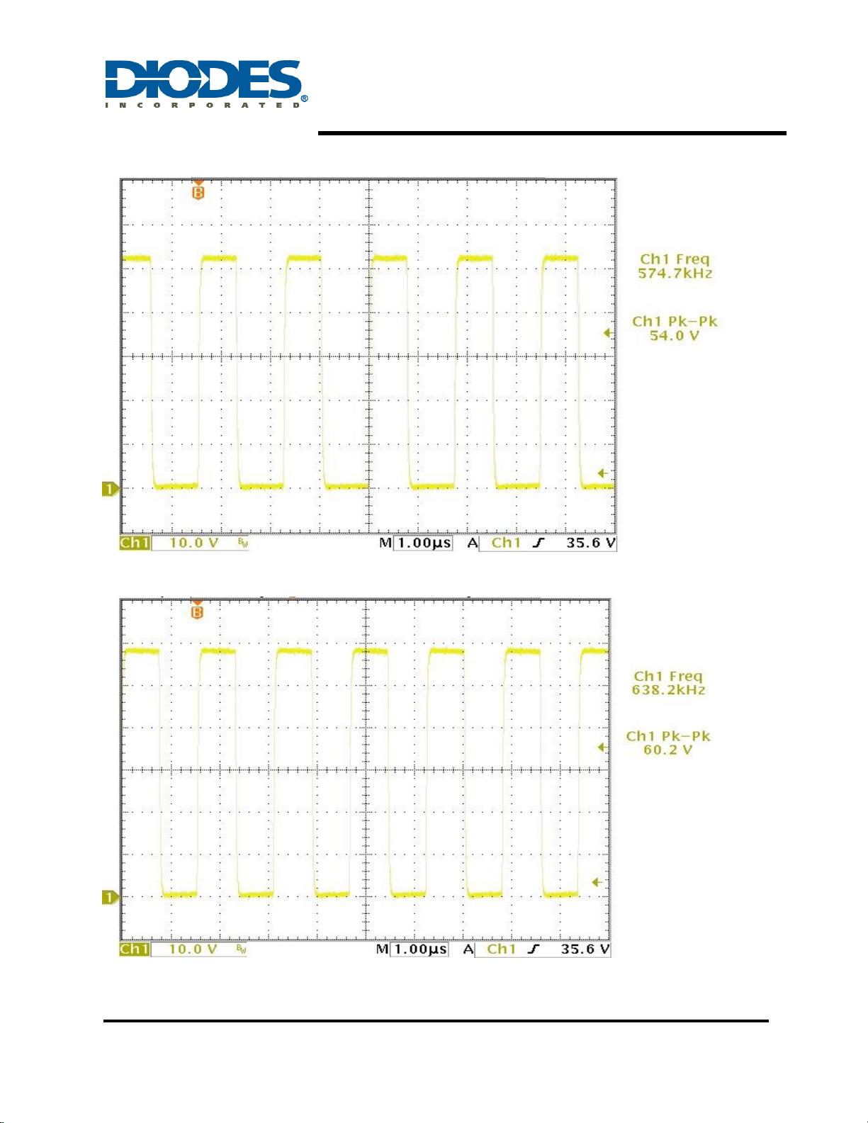
Waveform #1 (Voltage across Drain and Source, Vin=15VDC, ILED=1.5A)
Waveform #2 (Voltage across Drain and Source, Vin=20VDC, ILED=1.5A)
ZXLD1370/1EV4 Board
Condition: IN=15VDC; OUT=9 LEDs in series / 1.5A
ZXLD1370/1EV4 Board
Condition: IN=20VDC; OUT=9 LEDs in series / 1.5A
ZXLD1370/1EV4 User Guide
1.5A 40W Buck-Boost LED Driver
ZXLD1370/1EV4 Rev2 Page 9 of 11
October 2016
www.diodes.com
Waveform #3 (Voltage across Drain and Source, Vin=24VDC, ILED=1.5A)
Waveform #4 (Voltage across Drain and Source, Vin=30VDC, ILED=1.5A)
ZXLD1370/1EV4 Board
Condition: IN=24VDC; OUT=9 LEDs in series / 1.5A
ZXLD1370/1EV4 Board
Condition: IN=30VDC; OUT=9 LEDs in series / 1.5A

ZXLD1370/1EV4 User Guide
1.5A 40W Buck-Boost LED Driver
ZXLD1370/1EV4 Rev2 Page 10 of 11
October 2016
www.diodes.com
Waveform #5 (Output Voltage Ripple, Vin=20VDC, ILED=1.5A)
ZXLD1370/1EV4 Board
Condition: IN=20VDC; OUT=9 LEDs in series / 1.5A
ZXLD1370/1EV4 User Guide
1.5A 40W Buck-Boost LED Driver
ZXLD1370/1EV4 Rev2 Page 11 of 11
October 2016
www.diodes.com
IMPORTANT NOTICE
DIODES INCORPORATED MAKES NO WARRANTY OF ANY KIND, EXPRESS OR IMPLIED, WITH REGARDS TO THIS
DOCUMENT, INCLUDING, BUT NOT LIMITED TO, THE IMPLIED WARRANTIES OF MERCHANTABILITY AND FITNESS FOR A
PARTICULAR PURPOSE (AND THEIR EQUIVALENTS UNDER THE LAWS OF ANY JURISDICTION).
Diodes Incorporated and its subsidiaries reserve the right to make modifications, enhancements, improvements, corrections or other
changes without further notice to this document and any product described herein. Diodes Incorporated does not assume any
liability arising out of the application or use of this document or any product described herein; neither does Diodes Incorporated
convey any license under its patent or trademark rights, nor the rights of others. Any Customer or user of this document or products
described herein in such applications shall assume all risks of such use and will agree to hold Diodes Incorporated and all the
companies whose products are represented on Diodes Incorporated website, harmless against all damages.
Diodes Incorporated does not warrant or accept any liability whatsoever in respect of any products purchased through unauthorized
sales channel.
Should Customers purchase or use Diodes Incorporated products for any unintended or unauthorized application, Customers shall
indemnify and hold Diodes Incorporated and its representatives harmless against all claims, damages, expenses, and attorney fees
arising out of, directly or indirectly, any claim of personal injury or death associated with such unintended or unauthorized
application.
Products described herein may be covered by one or more United States, international or foreign patents pending. Product names
and markings noted herein may also be covered by one or more United States, international or foreign trademarks.
This document is written in English but may be translated into multiple languages for reference. Only the English version of this
document is the final and determinative format released by Diodes Incorporated.
LIFE SUPPORT
Diodes Incorporated products are specifically not authorized for use as critical components in life support devices or systems
without the express written approval of the Chief Executive Officer of Diodes Incorporated. As used herein:
A. Life support devices or systems are devices or systems which:
1. are intended to implant into the body, or
2. support or sustain life and whose failure to perform when properly used in accordance with instructions for use provided
in the labeling can be reasonably expected to result in significant injury to the user.
B. A critical component is any component in a life support device or system whose failure to perform can be reasonably expected
to cause the failure of the life support device or to affect its safety or effectiveness.
Customers represent that they have all necessary expertise in the safety and regulatory ramifications of their life support devices or
systems, and acknowledge and agree that they are solely responsible for all legal, regulatory and safety-related requirements
concerning their products and any use of Diodes Incorporated products in such safety-critical, life support devices or systems,
notwithstanding any devices- or systems-related information or support that may be provided by Diodes Incorporated. Further,
Customers must fully indemnify Diodes Incorporated and its representatives against any damages arising out of the use of Diodes
Incorporated products in such safety-critical, life support devices or systems.
Copyright © 2016, Diodes Incorporated
www.diodes.com
This manual suits for next models
1
Table of contents
Other Diodes Motherboard manuals

Diodes
Diodes AL5802EV1 User manual

Diodes
Diodes AP3981D2 User manual

Diodes
Diodes AP63356Q-EVM User manual

Diodes
Diodes AP3983R User manual

Diodes
Diodes AP3041EV1 User manual

Diodes
Diodes AP3981B User manual

Diodes
Diodes PI6CG18801 Mounting instructions

Diodes
Diodes EV1 User manual

Diodes
Diodes ZXLD1374QEV1 User manual

Diodes
Diodes AL8400QEV1 User manual

Popular Motherboard manuals by other brands


Supermicro
Supermicro X7DCU user manual

DFI
DFI AL102 user manual

Precision Microdrives
Precision Microdrives Haptic Feedback Evaluation Kit quick start guide

CSS Laboratories
CSS Laboratories MB-P201 Technical reference

Biostar
Biostar J1800NHL manual

Texas Instruments
Texas Instruments TPA2028D1YZFEVM user guide


