Dipol TFA 2.0 SL User manual

TFA 2.0 SL / 2.8 SL
Thermal imaging monocular/
front attachment
MANUAL

EN
2
CONTENT
Scope of delivery
2
Important notes & warnings
3
Application
3
Design
4
Technical Data
6
Operation & Quick Settings
10
Main Menu
14
Adjustment
24
Accessories
26
Possible errors & troubleshooting
27
Storage and transport
28
Quality Certificate
29
Warranty
30
Manufacturer & Sales
Certificate of conformity
31
ATTENTION!
BEFORE PUTTING THE APPLIANCE
INTO OPERATION, CAREFULLY
READ THE OPERATING
INSTRUCTIONS!
SCOPE OF DELIVERY
- TFA device
- Kordura pouch
- Lens cleaning cloth
- Manual
- USB cable with locking cap

EN
3
IMPORTANT NOTES & WARNINGS
Never look with the device in the sun or other
intense heat sources, this can lead to damage of
the sensor!
Protect the device from strong side impacts.
Only use optical cleaning cloths when
cleaning glass surfaces.
Remove the batteries to store.
Use batteries and power supplies from
reputable manufacturers.
Wait 3-5 seconds before switching the device
on again.
APPLICATION
The device is designed to observe moving and
immovable objects in different lighting
conditions as well as limited visibility (fog, dust,
etc.).
The device can be used to display locations and
objects of a temperature different from the
environment. It can e.g. used by guardians,
tourists, hunters, fishermen to explore the
terrain, detection and recognition of different
objects and nature observation.
Please note that the use of the device on a
riflescope is restricted in many European
countries without a special permit. Follow state
laws and applicable legislation!

EN
4
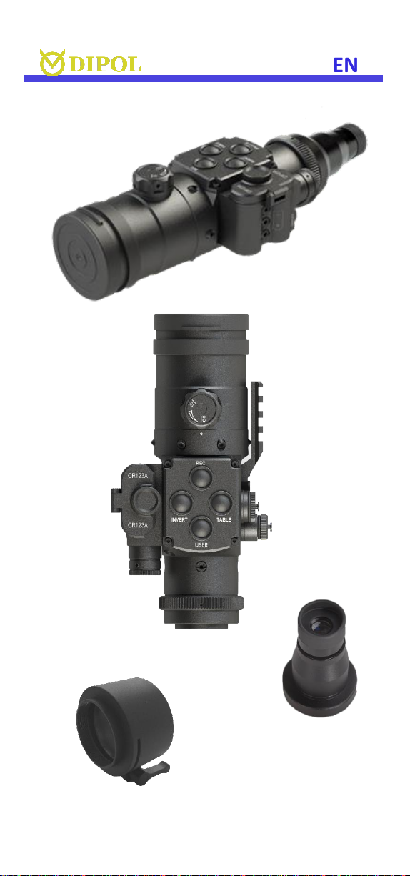
DESIGN
1. ON/OFF button
2. Objective rubber cover
3. Focusing knob
4. MENU controller
5. Battery compartment
6. Power-on indicator
7. INVERT button
8. REC button
9. TABLE button
10. USER button
11. USB type C sloth
12. Jack 2.1 sloth
13. Support weaver rail
14. Eyepiece (optional)
15. Locking ring
16. Clamp adaptor (optional).
3
11
9
EN
5
5
8
1
2
14
6
5
3
3
8
7
9
10
5
4
13
11
12
9
15
16
14

EN
6
TECHNICAL DATA
2.0 SL / 2.8 SL
Sensor, pixel/pitch
384x288, 17µm
Micro display, pixel
OLED 1024x768
Focal length/ aperture ratio
F40, 1,0/
F55, 1,0
Exit pupil, mm
30
Magnification: clip-on mode
monocular mode
1x
2х
Field of view
9,3°х7,0°/7,5°x5,6°
Detection range by Johnson
criteria(for objects 0.5x1.8m),m
up to 2000 /
2800
Spectral range, micrometre
8-14
Frequency, Hz
50
Colors / Inversion
9 +1 / yes
Max. impact load, G
600
Batteries, type
2 x CR123A
Accumulators, type
2 x LC16340**
Outer supply: Jack 2.1
USB
Jack 2.1/9,5-14,5 V
USB Type C/5 V
Operation time with full
batteries (+20°)
not less than 4 h
Operational temperature, °C
- 20 ... +50 °C
Videorec. temperature, °C
-15... +50 °C
Internal SD card capacity
32 Gb
Degree of protection
IP66
Dimensions, mm
175x76x105 /
201x76x105
Weight, kg
0,57 / 0,6
The technical characteristics can be changed by the
manufacturer without prior notice, while maintaining the
existing functionality of the device
Strongly recommend to use LC16340 batteries with a
voltage of 3.7-4.2 V for correct display of the charge level

EN
7
OPERATION & QUICK SETTINGS
Insert the batteries according to the polarity
shown on the battery compartment (5) and
remove the lens cover (2). Switch on the device
by pressing the ON / OFF button (1). The control
indicator (6) now lights up red. The complete
switching on process should not take longer
than 3-5 seconds. The device is completely
ready for operation after the following view
appears.
If the light indicator does not light up or blinking
and the battery status indicator at the bottom
right of the display is not visible or blinking, the
battery charging or charging of external power
sources must be checked.
----------------------
If the power supply taking place via the USB type
C slot, a USB symbol will be displayed instead of
the battery status sign.
----------------------
While using rechargeable elements instead of
batteries, the battery indicator changes its color
to blue.
----------------------
The image on display can be warm to cold tones;
it is not a defect.
To be able to use the thermal imaging
monocular with other optical devices you may
need a suitable adapter.

EN
8
First, loosen the locking screw on the locking
ring (15) on the ocular side of the device with
the enclosed key. Now screw the adapter (16)
on, place it into desired position and fix it with
the locking ring (16). The locking ring have to
be tightened again after that.
After using the device, close the objective with
the lens rubber cover (2) and switch off the
device by pressing the ON/OFF button.
Use as stand-alone device
With the optional eyepiece (14) you can use
your TFA device as an independent observation
device. First, attach an eyepiece to the ocular
part of the device with a suitable adaptor. After
that, adjust the sharpness of all display
indications with the eyepiece (14). Then point
the device at the object to be observed and
adjust the sharpness of it with the focusing knob
(3).
Choose in Main menu (for enter in Main menu
press and hold MENU button): Main menu –
Type of device –Monocular.
Use with day optics
To be able to use your TFA device with other
(day) optics, the suitable adapter is required
with inside diameter corresponding to the
outside diameter of the day optics’ objective. As
described above, firsts the display sharpness
has to be adjusted with daytime optics. After
that, the observed objects’ sharpness to be
adjusted with the focusing knob (3).
Choose in Main menu (for enter in Main menu
press and hold MENU button): Main menu –
Type of device –Clip-on.

EN
9
Color inversion
Hot black / hot white colours are usual default
setting.
Briefly press the INVERT button (7) to select the
required image polarity: e.g. “hot black”or “hot
white”.
For change the palette please use suited chapter
in main menu (Main menu –Color palette) or
use the programmable button USER (for more
details see p. Main menu)
All existing colours palettes can be inverted. The
selected polarity is shown on the display for a
moment (normal) or (inverted).
Quick settings: display & thermal sensor
With the MENU controller (4) you can adjust the
brightness of the display (Display Brightness /
BR), the sensor sensitivity (Thermal sensitivity /
SN), digital image enhancement (Image Detail
Enchancement / IDE) and sensor performance
level (Thermal image gain / GN).
The individual setting modes can be seen on the
display as shortcuts (here e.g. GAIN):
To set the optimal sensor performance (GN),
choose the suitable value from -10 to +10 by
turn the MENU controller (4).
To adjust the brightness of the display, short
press MENU controller (4) for selecting BR

EN
10
adjustment mode and choose the suitable value
from 1 to 30 by turn the MENU controller (4).
To set the optimal sensor sensitivity (values
from 40 to 80) short press MENU controller (4)
for selecting SN adjustment mode and turn the
MENU controller (4) for optimal result.
To set the optimal level of digital image
enhancement (values from 0 to 7), press the
MENU controller (4) until (IDE) mode appears
on the screen then rotate controller (4) to set
optimal level.
For repeatability control, the OSD table can be
called up by pressing TABLE button (9) briefly
every time you re-attach your TFA device, the
adapter opened and device moved slightly so,
that the four-field matrix lies on the marking of
the day optics. The adapter must then be closed
up again.
This control procedure is usually not necessary
though, with a good adapter the devices are
repeatable.
Read about the Position profiles in the following
chapter.

EN
11
MAIN MENU
To call up the main menu, keep the MENU
multifunction button (4) pressed until the main
menu appears in the field of view.
To move up and down in the menu, turn the
MENU controller (4) in each direction. Choose
menu lines by briefly pressing the MENU
controller (4). Exit menu lines by pressing the
MENU controller (4) again.
To exit the main menu, press and hold the
MENU controller (4). The main menu also
disappears automatically after 15 seconds of
inactivity.
The selected setting modes with their current
values are shown at the bottom of the status bar.
Picture Profile (P)
The TFA device already has three User profiles
(User 1, User 2 and User 3), which can be
customized and three pre-installed profiles (Fix
1 Woods, Fix 2 City, Fix 3 Mountains), which
have initial adjustments setups for those
conditions.
Each profile can be customized. All your
adjustments (color palette, polarity, sensor gain
level, etc) automatically will be saved in current
profile, but in case to repeated choosing “Fix ...”

EN
12
profile all your adjustments will be cancelled
and restore to initial for this “Fix” profile.
Note: Switching the profiles should be done with
a delay of 3-4 seconds for change settings.
Color palette
You can choose from 10 available colour
palettes, which are displayed when you first call
up the "Color palette" menu item.
Note: the settings of the selected palette are
saved after the device is switched off.
Palette on button “USER”
You can quickly select a different color palette
than defined in the basic setting (Color Palette).
Note: This menu item will be displayed only if in
item “USER button function” will be chosen item
“Color palette”.
Thermal image gain (GN)
Here you can determine the performance of the
thermal imaging sensor. This setting process is
also described in detail in the operation & quick
settings chapter.
Display brightness (BR)
The display brightness will be adjust in this unit.
Thermal sensitivity (SN)
The sensitivity of the thermal sensor can be
adjusted here.
Image Detail Enhancement (IDE)
Settings for increasing the general image
detail/smooth.
Image Polarity Inversion
In this item you can choose image polarity (hot
–black or hot –white). Color palettes also can
be inverted.
Super contrast display mode
Increases the contrast and image quality,
especially with insignificant temperature
differences for observed objects or
backgrounds.

EN
13
USB data transfer to PC
Enables the copying and deletion of video files
from the built-in memory card. Plug USB type C
cable to slot (11) and other cable side connect
to PC USB slot, then select this chapter and press
MENU controller (4) for confirm.
You will see the sign "Establishing connection
..." on the screen, and the device will soon be
visible as a flash drive in PC.
For prevent troubles with connection or if sign
“Replace the power source” strongly
recommended to use branded USB cable and
plug device to 2.0 USB sloth or higher in your
computer.
For exit data transfer mode turn off the device
and disconnect it from PC.
Video recording mode
You can choose either normal start or quick
start for video recording.
In normal start mode, the video recording starts
with a slight delay (up to 10 seconds) after the
"REС" button (8) is pressed to switch on the
corresponding module and load the software.
In the quick start, modules and software loading
are activated just after the pressing the "REС"
button. Videos are recorded up to 5 seconds
faster after the REC button is pressed.
The following indicators are visible in the status
bar during video recording:
REC (blinking) -recording module active
REC - ready to record
REC 00:01:20 - recording
REC Saving - internal storaging running
Note: the battery consumption is greater in the
video recording mode as well as during the quick
start.

EN
14
To reduce power consumption, you can press
and hold the “REC”button (8) for a few seconds
and turn off the video module.
After that, it takes some time for to start
recording video again, similar as during the
normal start mode.
Note: video recording is not possible if the
internal or external power sources are not
sufficiently charged. Due to that reason, the
recording also can stop automatically.
Date and time stamp position
In this chapter you can choose location place
either set or not a date and a time of the video
recording that can be displayed during
recording time.
Auto bad pixel correction
After an automatic correction of defective
pixels, press and hold the MENU controller (4)
to save changes or briefly press the MENU
controller (4) to cancel the changes.
PLEASE NOTE, THAT THE OBJECTIVE LENS
MUST BE COVERED DURING THE AUTO PIXEL
CORRECTION!
Manual bad pixel correction
In this mode, individual defective pixels or pixel
groups can be corrected manually. Please note
that the correction of a pixel group from its
edges to the center must be done by gradually
reducing the radius of the group.
By turning the MENU controller (4), the
marking cross can be moved over the field of
view (note: with constant rotation, the
increment of the shift increases!).
The coordinate axis of the cross movement can
be changed by briefly pressing the MENU
controller (4). After the cursor is positioned as

EN
15
precisely as possible over the defective pixel,
briefly press the ON / OFF button (1). The pixel
then changes colour.
Repeat the process with other defective pixels if
necessary. To save the changes, press and hold
the MENU controller (4).
PLEASE NOTE, THAT THE OBJECTIVE LENS
MUST BE COVERED DURING THE AUTO PIXEL
CORRECTION!
‘ON-OFF’ button function
In this unit you can select one of the available
functions for quick access via the ON-OFF
button:
- display ON-OFF,
- Super contrast,
- Picture profile.
If you chose a “monocular” mode in the section
“Type of device” (see suited section) than
functions list will be the same.
‘User’ button function
In this unit, you can select one of the available
functions for quick access via the USER button
on the top of the device:
- Picture profile,
- Color palette,
- Super contrast.
If you chose the “monocular” mode in the
section “Type of device” (see next up) than
functions list will be the same.
Status bar position
Allows to choose a spot of the status line/bar
during video recording process in the field of
view.

EN
16
Status bar delay time, s
Here you can set the inactive time (in seconds),
after which the status bar disappears from the
screen.
The following chapter available in menu only in
“Monocular” mode!
Menu position
In this chapter you can set status line location in
the field of view.
OSD transparency
In this chapter you can increased/decreased
Main menu/table/status line transparency on
the screen.
Auto power-off, minutes
Allows the device to turn off automatically after
a period of inactivity (in minutes).
The following 4 chapters available in menu only
in “Clip-on” mode!
Position profile
This MENU mode allows quick switch between
Image position and OSD position setting pairs
(each setting pair = correction/sight in profile).
There are 5 profiles avaliable.
Important: here you do not change your Picture
profiles (s. page 11).
Important: all correction profiles are saved
automatically after changing them!
Image position correction
Here you can move the image on the micro
display according to the sight in of your day
optics (see chapter ADJUSTMENT).

EN
17
OSD position correction
Here you can place the quick settings table in
the position on the micro display, which allows
your to check the mounting correctness of the
re-attached TFA device (see chapter
ADJUSTMENT).
Restore position settings
Allows to reset Image position and Table
position to factory defaults.
Date set
In this section you can set the date to be
displayed during video recording. The setting is
made by pressing and turning the MENU
controller (4).
Time set
Here you can set the time that is displayed
during video recording or video transmission.
The setting is made by pressing and turning the
MENU controller (4).
Please note that the date and time settings are
not lost after the power elements are switched off
or removed.
However, if the device has been switched off for a
longer period (longer than 4 months), the date
and time settings may need to be made again.
Clear video record storage
Here you can delete ALL video recordings from
the internal SD memory card without having to
connect the device to a PC.
Language
Allows you to select the language for the user
interface. Russian, English, German, Spanish are
available.

EN
18
Type of device.
You can choose device type: clip-on or
monocular.
In monocular mode you can use device with
additional ocular for observation. Also in this
mode changed Basic menu position and main
screen view will changed to :
In this mode you can use digital zoom: press
TABLE button for desired level (2x, 4x).
Note: digital zoom multiply device optical
magnification (for example, in monocular mode
with 2x magnification ocular on zoom level 4x
the device will have 8x magnification).
Version of the video recording module.
Shows video recording module version.
Software version
Displays the version of the installed device
software.
Settings reset
Here the current device settings can be reset to
the factory settings. Please note that the quick
settings of the image and sensor, as well as the
settings in the user profiles remain unchanged!
Briefly press the MENU controller (4) and select
“Yes” by turning. Briefly press the controller to
confirm.
Please note that a reset is not possible during
video recording!
Note: Menu content may vary very
insignificantly to improve the operation of the
device depending to software version. In case of
any questions, please, contact to the company-
manufacturer.

EN
19
ADJUSTMENT
Make sure that your day optic is sighted in at
100 m.
• Point your day optic exactly at a relatively
small warm object (e.g. a hand warmer) at a
distance of approx. 100 m and fix it solidly in
this position e.g. in a vice.
• Mount the TFA device on the objective of your
day optics using a high-quality clamp adapter.
• Switch on the TFA device, open the objective
cover and look through the whole system again.
• If the observed object is no longer in the centre
of the reticle, it must be “moved”back there.
• To do so, press and hold the MENU controller
(4) and select the "Image position correction"
in the main menu (make sure that Clip-on mode
has been enabled first).
• First move the object along the X-axis
(horizontal directional arrows) by turning the
MENU controller (4) and confirm the
correction.

EN
20
• Now move the object along the Y-axis (vertical
directional arrows) in the same way and
confirm the correction.
• Go back to the main menu (press and hold the
MENU controller (4) and select the menu line
"Table position correction".
• In the same way as described above, move the
square table that appears so, that its centre lies
exactly above the object/reticle.
• Confirm and exit the main menu.
For repeatability control, the quick settings table
can be called up briefly every time you re-attach
your TFA device, the adapter opened and device
moved slightly so, that the four-field matrix lies
on the marking of the day optics. The adapter
must then be closed up again. This control
procedure is usually not necessary though, with a
good adapter the devices are repeatable.
ACCESSOIRES
The device offers the possibility of connecting
an external power source with 9.5-14.5 V with a
JACK 2.1 connector (12).
It is also possible to supply the device with an
external power source via the USB type C
connector (11) with a voltage of 5 V.
Other manuals for TFA 2.0 SL
1
This manual suits for next models
1
Table of contents
Other Dipol Monocular manuals


