Diva La Premiere User manual
Technical manual
to be saved
by the user
for future reference
Harworth Heating Ltd
Blythe Road
Harworth
Doncaster
DN11 8NE
Tel: 01302 742520 Fax: 01302 750573
Email: sales@oilstoves.co.uk
Diva
Central heating cooker «La Premiere»
Ref. 82 914 - 22 kW
Ref. 82 916 - 29 kW
Description of the appliance
Installation instructions
Operating instructions
Spare parts
Warranty certificate

Description............................39
Package.............................39
Optional equipment . . . . . . . . . . . . . . . . . . . . . . 39
Technical details . . . . . . . . . . . . . . . . . . . . . . . . 39
Assembly and installation . . . . . . . . . . . . . . . . . . . 41
Positioning the cooker . . . . . . . . . . . . . . . . . . . . . 41
Mounting ............................41
The chimney . . . . . . . . . . . . . . . . . . . . . . . . . . 42
Connection to chimney. . . . . . . . . . . . . . . . . . . . . 42
Connecting the central heating circuit. . . . . . . . . . . . 42
Adjustments . . . . . . . . . . . . . . . . . . . . . . . . . . 43
Operating instructions . . . . . . . . . . . . . . . . . . . . . 45
Checks prior to lighting . . . . . . . . . . . . . . . . . . . . 45
Fuel ............................... 45
Lighting . . . . . . . . . . . . . . . . . . . . . . . . . . . . . 45
Operation . . . . . . . . . . . . . . . . . . . . . . . . . . . . 46
Flue draught control box . . . . . . . . . . . . . . . . . . . 47
Maintenance . . . . . . . . . . . . . . . . . . . . . . . . . . 48
Fault diagnosis. . . . . . . . . . . . . . . . . . . . . . . . . 49
Spareparts............................51
Page
Contents
Document n° 66-5EN ~ 18/01/1999
Central heating cooking Diva - "La Premiere" 82 914 - 82 916
38 Technical manual

1. Description
1.1. Package
1 package
1.2. Optional equipment
• Cover in 2 parts in case of a rear flue outlet
• Cover in 3 parts in case of a top flue outlet
1.3. Technical details
Model .........................................82.914 . . . . . . 82.916
Capacity of water jacket . . . . . . . . . . . . . . . . . . . litres . . . . . . . . . . 22 . . . . . . . . . 25
Weight.............................. kg......... 330........ 335
Firebox
Width ............................. mm......... 300........ 300
Depth ............................. mm......... 447........ 447
Height(maximum) ...................... mm......... 440........ 440
Oven
Width ............................. mm......... 410........ 410
Depth ............................. mm......... 400........ 400
Height............................. mm......... 320........
320 Flue outlet O/D (2) . . . . . . . . . . . . . . . . . . . . . . mm . . . . . . . . . 153 . . . . . . . .
82.914 82.916
Total heat output
(Btu/hr)
Maximum water
heating output**
(Btu/hr)
Total heat output
(Btu/hr)
Maximum water
heating output**
(Btu/hr)
Grates in top position Wood* 44.000 32.000 59.000 47.500
Solid fuel 55.500 42.000 75.000 63.000
Grates in lowest position Wood* 67.000 53.000 87.000 73.000
Solid fuel 71.000 57.000 91.000 77.000
*When burning dry seasoned wood.
**Water output is measured at a flue draught of 0,006" water gauge and on a loading cycle of 31/2 hours for solid fuel.
Fig. 1
Fig. 1 - Dimensions in mm
Document n° 66-5EN ~ 18/01/1999
82 914 - 82 916 Diva - "La Premiere" Central heating cooking
Technical manual 39

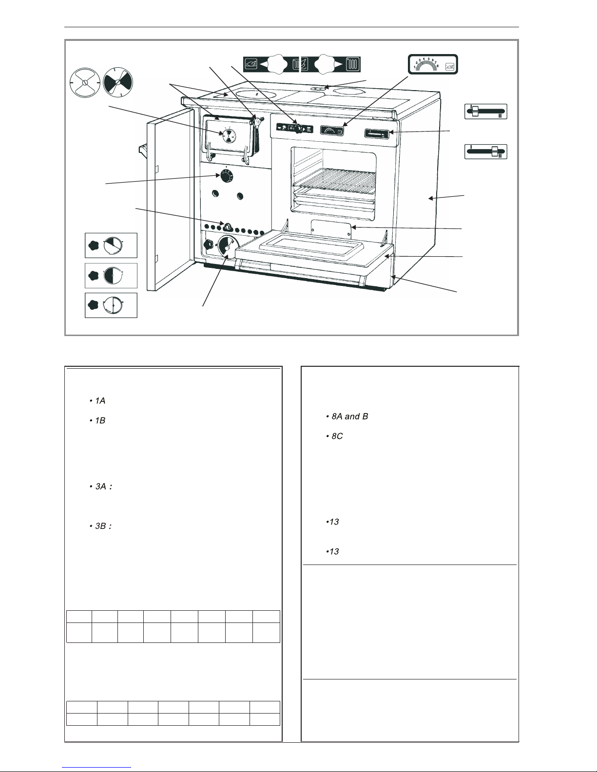
Fig. 2 - Operating description of the appliance
1Secondary air control
2Handle and lock
3The two position heating/cooking control knob.
4Top or front loading. The firebox design allows
solid fuel, wood or peat to be burned with equal
efficiency and economy.
5Thermometer
6The thermostat automatically regulates the bur-
ning rate and helps to maintain a constant pre-
determined water temperature.
7A lifting mechanism adjusts the height of the
oscillating grates to allow flexibility of firebox size
and heat outputs according to needs.
8Manual air inlet control.
9Easily removed, double glazed, oven door to
simplify cleaning.
10 Cleaning access.
11 Storage / Warming cupboard.
12 The side panels have highly efficient insulation.
13 Direct draught control.
Fig. 3 - Front cross section
: Control knob in heating position.
: Control knob in cooking position.
1Water flow.
2Water return.
3Top plate shield (82.914).
4Fire-brick (82.914).
Fig. 4 - Side cross section
1Water flow.
2Rear flue outlet.
3Firebox grates.
4Water return.
5Ash pan.
1
3
2
4
6
11
9
10
12
510
8
7
13
Fig. 2
1
2
1
3
2
4
Fig. 3
Document n° 66-5EN ~ 18/01/1999
Central heating cooking Diva - "La Premiere" 82 914 - 82 916
40 Technical manual

2. Assembly and installation
Please read and understand thoroughly before com-
mencing installation.
FRANCO-BELGE recommends that the installation of
all their products is undertaken only by qualified
heating engineers who are experienced in solid fuel
heating.
The installation must be in accordance with current
Building Regulations and Codes of Practice.
2.1. Positioning the cooker
The room in which the cooker is to be installed must
satisfy all local regulations
These will stipulate an adequate fresh air inlet of at least
350 cm . This must be situated in such a way, that in
adverse wind conditions the air flow cannot be reversed
as this may suck air out of the room in which the unit is
installed.
2.2. Mounting
The guard rail, firebox and oven door handles are not
fixed on the cooker to avoid damage during transit.
2.2.1. Covers
Locate the lugs 2 (ill. 5) of the covers in the holes at the
rear of the top plate. Fit the handles 1 on the covers.
2.2.2. Guard rail and firebox door
Fit the guard rail and the firebox door handle with the
screws supplied (ill. 6).
12 1
2
6
7
8
9
10
11
3
4
5
Fig. 4
6Grate bar.
7Secondary air inlet.
8Thermostat.
9Hole for riddling.
10 Primary air inlet
11 Threaded lifting bar
12 Top plate shield (82.914).
Fig. 5 - Optional insulated covers
- Rear flue outlet : cover in 2 parts.
- Top flue outlet : cover in 3 parts.
1Handles.
2Hinges.
Fig. 6 - Guard rail and fire box door handle
1Rail.
2Firebox door handle.
Fig. 5
2
1
2
1
2
1
1
1
2
1
Fig. 6
Document n° 66-5EN ~ 18/01/1999
82 914 - 82 916 Diva - "La Premiere" Central heating cooking
Technical manual 41
Lids No Longer
Available
Lids No Longer
Available
Lids No Longer
Available
2

2.2.3. Lower oven compartment door
If required a handle for the lower oven
compartment door is packed inside the unit.
2.2.4. Oven door handle
To fit the oven door handle :
- Remove the oven door 8 (ill. 7).
- Remove the two screws 1 (ill. 7) and hold the inner
door 4 half open with a block 2.
- Unscrew the struts 6.
- Place the nuts 7into the slot of the handle supports 5
et place the fiber washer 3 between the handle and the
door.
- Centre the handle before screwing up the struts.
- Fit the inner oven door and replace the oven door.
2.3. The chimney
The chimney is the key to a successful installation and
the following key areas should be checked.
Height
The minimum height should be 5 metres with the termi-
nal at least 1 metre from the roof surface and in a clear
area away from possible downdraft. If in doubt always
increase the chimney height. This will help to ensure an
adequate draft and clearance of the flue gases from the
area of the building.
Insulation
The chimney needs to be warm from bottom to top and
should be adequately insulated. Cold chimney and cool
flue gas temperature will result in tar formation
and smoke emission into the room.
Resistance
If the chimney has a horizontal section at the appliance
outlet, this should not exceed 30 cm. Any changes in
direction should be gradual (15 degrees maximum) and
the chimney system must not incorporate more than two
bends. The straighter the chimney, the less resistance.
Any resistance will slow down the flue gases and help
to create a build up of tar deposits.
Draft
The appliance requires a draft of between 04" and 07"
W.G. to burn effectively. This is the up draft of air through
the appliance. It is the result of the height of the chimney
and heating of the column of air within the chimney. An
inadequate draft will cause soot and tar formation in the
chimney.
The appliance requires a class 1 chimney. Existing un-
lined chimneys should be lined with a liner suitable for
use with solid fuel burning appliances. If there is no
existing chimney, there are a variety of prefabricated
systems available and it is recommended to
discuss your particular application with a chimney
specialist.
2.4. Connection to chimney.
• TOP FLUE OUTLET
Use the draught control box (ill. 17).
The draught control box can be dismantled to give
access for flue cleaning.
• REAR FLUE OUTLET
It is not possible to use the draught control box in this
position. Provision should therefore be made to fit a
draught regulator.
Important ! When the rear flue connection is used, cut
Don’t forget to fit with an airtight seal the flue collar and
the blanking plate which are supplied and packed in the
firebox.
Caution : Sufficient access must always be left for chim-
ney sweeping and appliance cleaning.
2.5. Connecting the central heating cir-
cuit.
In any installation, Relevant Building Codes and Practi-
ces must be observed.
• The appliance is not designed as a pressure vessel,
so the circuit must be left open to the atmosphere and
must not be constructed to allow any pressure build-up
to occur (ill. 8).
• A gravity circuit MUST be provided, as a fail safe heat
loss in the event of a circulating pump failure or a power
cut. To achieve this, ensure that large diameter pipes
leading to upstairs radiators have a direct flow from the
boiler, or install a big hot water cylinder with large
diameter heat exchanging coil, situated above the coo-
ker.
The layout of the heating circuit can be designed in any
fashion that suits the house, as the pump will ensure
circulation of hot water to all points, but the hot water
cylinder or a small heating circuit must be engineered
to work by gravity, Use 1 inch min. I.D. pipe (28 mm) to
the cylinder, ensure that the cylinder has a 314 inch
min. I.D. coil wound from top
to bottom, and that the inlet is above the boiler and the
outlet is above the return tapping of the boiler.
14
2
6
8
3
7
5
Fig. 7
Fig. 7 - To fit the oven door handle
1Screw.
2Block.
3Fibre washer.
4Inner oven door.
5Handle.
6Strut.
7Nut.
8Oven door.
Document n° 66-5EN ~ 18/01/1999
Central heating cooking Diva - "La Premiere" 82 914 - 82 916
42 Technical manual

• An expansion tank open to the atmosphere must be
provided to ensure that no pressure build-up can occur,
and this should be connected to the highest point of the
circuit by 1" I.D. pipe (28 mm). If the system is going to
be left unattended during winter periods, anti freeze
should be added. In the case of an installation coupled
to an automatic boiler, this should not be necessary.
N.B. This model has optional water tapping on the rear
or the left hand side of the cooker. Ensure unused
tapping are blanked off using the plugs supplied.
•lMPORTANT : In order to avoid condensation and low
temperature corrosion of the water jacket, the return
water temperature must not fall below 50°C. A four way
mixing valve should be used but it must be fitted in such
a way as to prevent the primary flow from being restric-
ted.
In addition a thermostat should be fitted on the gravity
return to switch the circulating pump off if the water
temperature falls below 50°C.
2.6. Adjustments
2.6.1. Ashpan door (ill. 9)
Once the door seal has bedded in, it may be necessary to
adjust the door to regain the airtight seal :
- Remove the stop 1.
- Unscrew the lever 2.
- Replace the stop 1.
2.6.2. Thermostat (ill. 10)
If adjustment is necessary, this is done by altering the nut
2on the lever arm.
- Remove the front protective panel by lifting it up.
- Then set the thermostat 1 in position “6".
When the water temperature reaches 60°C/146°F, the
damper should be closed.
If adjustment is necessary turn the nut, anticlockwise to
open the damper, clockwise to close the damper.
After adjustment, check that the water temperature is
maintained at 60°C/146°F.
Note to installer : Please ensure that the- se
instructions are handed to the user
upon completion of the installation.
2
3
4
5
6
7
8
9
10
1
Fig. 8
Fig. 8 - Example of installation
Pumped central heating, gravity hot water system, four
way mixing valve.
1Expansion tank.
2Sweep tee.
3Water cylinder.
4Adjustable non return valve.
5Pumped central heating.
6Circulating pump.
7Gravity circuit.
8Control valve.
9Four way mixing valve.
10 Limit stat set to switch pump off if water return is
less than 50°C.
2
1
Fig. 9
2
1
Fig. 10
Adjustment of the ashpan door
1 - Stop 2 - Lever
Thermostat setting
1 - Knob. 2 - Nut
Document n° 66-5EN ~ 18/01/1999
82 914 - 82 916 Diva - "La Premiere" Central heating cooking
Technical manual 43
1A 1B
1
3A 3B
3
2
4
6
11
9
10
12
5
10
8
7
8A
8B
8C
13 (ll)
13 (l)
13
Fig. 11
Fig. 11 - Operating description of the appliance
1Secondary air control :
: Closed : When burning wood or smokeless
fuels.
: Open or half open : When burning solid
fuel with high volatile contents (e.g. household
coal, soft coal), the secondary air inlet allows a
more complete combustion of the volatiles
produced.
2Handle and lock.
When the knob is turned to cooking and
the firebox has been stoked, the hot plates and
oven quickly heat up, without greatly affecting the
temperature in the central heating circuit.
When the knob is turned to heating, most
of the heat is absorbed by the heat exchanger
and transferred to the central heating circuit.
4Top or front loading. The firebox design allows
solid fuel, wood or peat to be burned with equal
efficiency and economy.
5Thermometer
Position on the thermometer
1 2 3 4 5 6 7 8
180°F 230°F 320°F 420°F 600°F 760°F 920°F 1060°F
Average temperature in the middle of the oven
6The thermostat automatically regulates the bur-
ning rate and helps to maintain a constant
prede- termined water temperature.
Thermostat control on position
2 3 4 5 6 7 8
66°F 86°F 106°F 126°F 146°F 166°F 186°F
Water temperature
7A lifting mechanism adjusts the height of the
oscillating grates to allow flexibility of firebox
size and heat outputs according to needs.
8Manual air inlet control :
: Open = Lighting, quick restoration of
the fire.
: Closed = normal.
9Easily removed, double glazed, oven door to
simplify cleaning.
10 Cleaning access.
11 Storage / Warming cupboard.
12 The side panels have highly efficient insulation.
13 Direct draught control :
I: Direct draught flap open :
The direct draught Control gives easier lighting
and quick restoration of the fire.
II : Closed = normal.
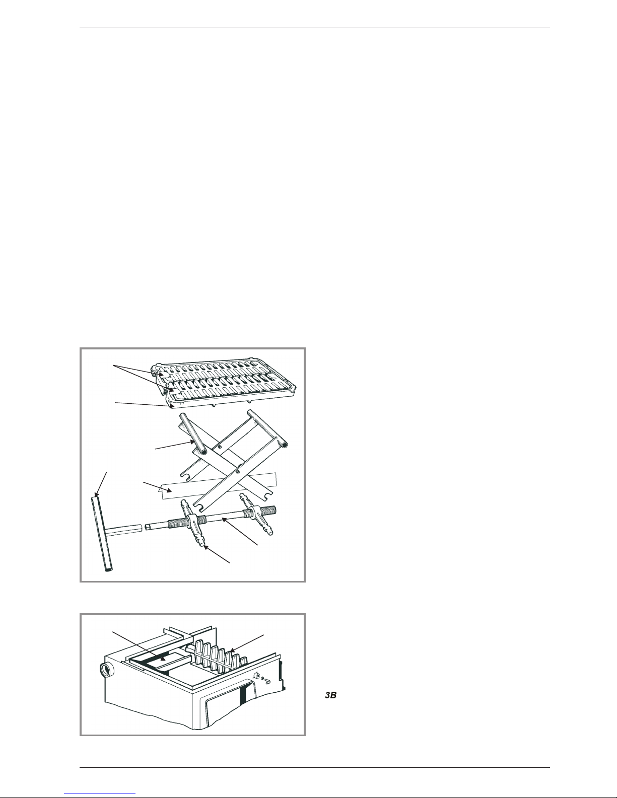
Fig. 12 - Oscillating grates mechanism
1Oscillating grates.
2Support grate.
3Lifting handle.
4Stainless steel screen.
5Cast iron nut.
6Lifting cradle.
7Screw.
Fig. 13 - Removable parts
1Top plate shield (82.914).
2Grate bar.
Document n° 66-5EN ~ 18/01/1999
Central heating cooking Diva - "La Premiere" 82 914 - 82 916
44 Technical manual
3. Operating instructions
3.1. Checks prior to lighting
Before lighting the cooker, check the following points :
• The water circuit is filled and has been tested for leaks.
• The cleaning access traps are closed (access plate on
top and front access trap below the oven door, and
beside the ash pan door).
• All the grates are in their correct positions.
• The cooking/heating control knob and the
direct draught flap move freely.
• The thermostat and its air inlet flap have been adjus-
ted.
• All chimney seals are airtight and the draught control
box mechanism is free.
3.2. Fuel
•Wood
In general any type of wood is suitable for use in a
Franco-Belge as long as the fuel is seasoned for a
minimum of 2 or 3 years and dried to a moisture content
of less than 20 %.
Hard woods such as oak or elm burn steadily giving an
even heat over a relatively long period of time.
Soft woods such as pine release their heat very rapidly
but their burning duration is very short. This makes soft
woods ideal for initial lighting or when quick heating of
the appliance is required (e.g. cooking or rapidly
heating domestic hot water).
The importance of burning dry seasoned wood cannot
be overstressed as wet fuel may lose up to 50 % of its
possible heat value, resulting in inadequate central
hea- ting and slow unresponsive cooking ; together with
rapid clogging of the flue-ways and chimney, which is
dange- rous and a fire hazard.
NOTE : Never burn wet or unseasoned wood.
•Peat
Same specifications as wood. The moisture content
must be less than 20 %. Failing to respect the before
mentioned points on seasoning fuel or moisture content
will void the guarantee.
•Solid fuels
Household coal is relatively soft. This makes it an easy
fuel to light which is responsive to air controlled regula-
tion. The output, although greater than wood is low in
comparison with other solid fuels. Whilst relatively
cheap, the disadvantage with this fuel is its impurities
which produce thick dense smoke which can quickly
clog the flue ways and chimney, and frequent attention
must be paid to keep them clean.
Smokeless fuels, such as Homefire, Coalite and Sun-
bright, are amongst the highest in heat value of solid
fuels. Their hardness and density makes them more
difficult to light and relatively slow in reacting to control
by air regulation but the lack of impurities makes this
type of fuel far cleaner and less attention has to be paid
to the flueways and chimney.
If you are restricted to using smokeless fuels, they must
have a long flame to allow quick response when coo-
king. Your local merchant should be able to assist you
in choosing the most suitable fuel for your needs.
In general, most owners of Franco-Belge appliances
find that by mixing their fuels, they will obtain the best
results for their individual situation.
Trial and error will tell you which mixture of fuels works
best for you. So please experiment with mixtures of
small quantities before placing your bulk order.
NOTE : If using bituminous coal, it must be of good
quality.
WARNlNG : When burning bituminous coal, care must
be taken when opening the firebox for loading or
inspec- ting the fire.
Coals disintegrating under heat and those producing
large amounts of ashes are not recommended for use
in these appliances.
3.3. Lighting
Place firelighters (or rolled newspaper and kindling
wood) on the grates and place 2 or 3 small logs on top
of firelighters.
- Set the thermostat in position “8".
- Place the control knob 3 (fig. 11) in cooking position
.
- Open the direct draught flap 13 (I).
- Open the manual air inlet control 8A.
Light the firelighters. Once the fire is burning well stoke
up with fuel.
- Close the direct draught control 13 (Il).
1
2
6
4
3
5
7
Fig. 12
12
Fig. 13
Document n° 66-5EN ~ 18/01/1999
82 914 - 82 916 Diva - "La Premiere" Central heating cooking
Technical manual 45

- Close the manual air inlet control 8B.
- Place the control knob in heating position .
- Set the thermostat.
CAUTlON : Ashpan door must be closed during opera-
tion to prevent overfiring.
REMARK : Should a small quantity of black water ap-
pear as a result of condensation when the unit is first lit.
Do not be concerned, close the 4 way valve and check
that the low limit stat is set correctly.
As the system heats up, gradually open the 4 way valve.
Should the problem persist, contact your installer to
check the good working of the 4 way valve and low limit
stat.
3.4. Operation
Lifting mechanism : (ill. 14, # 4)
Choose the height of the firebox grates according to the
heating requirements of individual needs (see technical
details).
If an intermediate output is required, place proportional-
ly the grates on an intermediate level.
The adjustment of the height of the grates is done by
turning the threaded lifting bar located on the front of the
cooker.
Use the lifting handle on the threaded lifting bar to alter
the grates
Secondary air control : (ill.11, #1)
Closed when burning wood or smokeless fuels.
Half open when loading and burning solid fuel with high
volatile contents. If the chimney draught is slow, open
the secondary air control more.
Experience will indicate correct setting.
Remarks about the use of fuels :
The amount of ash in the fire is a very important factor
in the performance of the Franco-Belge.
When burning wood, a good base of ashes is advanta-
geous for slow controlled burning, but should be redu-
ced by riddling before cooking, or whenever ash
accumulates too much and reduce the fire box capacity.
When burning coal or smokeless fuels, the ash must be
riddled more frequently to allow a good airflow to the
fire. Coal and especially smokeless fuel requires much
more air to burn than wood.
Guarantee: The use of unsuitable fuels will invalidate
the guarantee.
Loading :
The cooker may be loaded through the top or the front.
To obtain the best result and a long burning period, the
firebox should be loaded with fuel to within 2" (5 cm) of
the top of the right inside water jacket (or of the firebrick
for 82.914).
NOTE : When burning solid fuel with high volatile con-
tents, the firebox must not be loaded entirely. It is
recom- mended to load it step by step to allow all the
contents to be freely exhausted.
De-ashing :
The cooker may be de-ashed only when the oscillating
grates are in the lowest position 4 (ill. 14).
Lower the firebox grates if necessary and slide
the riddling handle into the front holes as shown 5 (ill.
14).
De-ash every morning and if required before each loa-
Fig. 14
6
3
5
4
7
2
Fig. 14 - Operating tools
1For lifting and locking the loading lid :
1 : Open.
1 : Off.
• 1 : Lifting (take the tool on the other side).
2For raising the left inset plate above firebox.
3Poker.
4Adjustment of the height of the grates :
To lower the grates, turn anticlockwise.
To raise the grates, turn clockwise.
5Riddling handle for de-ashing.
6For handling ash pan.
7Scraper for cleaning firebox and flue way.
Document n° 66-5EN ~ 18/01/1999
Central heating cooking Diva - "La Premiere" 82 914 - 82 916
46 Technical manual

3.4.1. Heating regulation
Normal rate
- Close the ashpan door and the manual air inlet control
8B (ill. 11).
- Place the control knob on heating position 3A.
- Close the direct draught flap 13 (Il).
- Set the thermostat control 6 between position “1" and
”8".
Provided that the firebox is well stoked with fuel, the
thermostat regulates the burning rate of the fire and
produces the required temperature.
NOTE : After every long burning period, run the ap-
pliance hot for at least 30 minutes to remove any resi-
dual tar and moisture.
Slow burning
- Riddle grates in lower position.
- Closed the ashpan door and the manual air inlet con-
trol 8B.
- Set the thermostat 6 on a low setting.
Note : If no central heating water is required :
- Raise the grates.
- Place the control knob on cooking position 3B.
- Open the direct draught flap 13 (I).
Note : If heating is required :
- Place the control knob in heating position 3A.
- Close the direct draught flap 13 (Il).
Stoke up with fuel when burning rate is stabilized.
Set the mixing valve on a low position to maintain the
temperature of return water at a minimum of 50°C.
Restoring the fire
- Riddle grates in lower position.
- Open the manual air inlet control 8A .
- Rise thermostat setting to “8".
- Place the control knob on cooking position 3B.
- Open the direct draught flap 13 (I).
- Stoke up with fuel.
- Close the manual air inlet control 8B.
- Place the control knob on heating position 3A.
- Close the direct draught control 13 (II).
- Set the thermostat.
3.4.2. Cooking regulation
1/2 hour before cooking :
- Riddle grates in lower position.
- Stoke up with fuel.
- Open the manual air inlet control 8A .
- Place the control knob on cooking position 3B.
•Hot plate cooking
If full use of the hot plate is required :
- Place the control knob on cooking position 3B.
- Open the direct draught flap 13 (I).
This will allow the whole hot plate area to be
heated without heating the oven.
lMPORTANT ! The direct draught lever must be
returned to normal running position after use.
When the appliance is turned to central heating posi-
tion, the area directly above the firebox will become hot
enabling a kettle to be kept simmering.
When there is a low fire, the hot plate will heat quicker
by raising the firebox grates to the top position.
When using the oven, the hot plate will in any case be
ready for use.
•Oven
To heat the oven :
- Place the control knob on cooking position 3B.
- Ensure that the direct draught flap is closed 13 (Il).
The temperature of the oven can be seen from
the thermometer on the front panel.
Regulation of the oven temperature is obtained by ope-
ning the manual air inlet control to decrease the tempe-
rature, or closing the manual air inlet control to increase
the temperature.
NOTE : As with any solid fuel cooker, there is no subs-
titute for experience, and with a little time and patience
you will soon learn what controls are necessary.
•Summer use
Provided the installation has a large hot water cylinder
and a heat leak radiator on gravity circulation, the ap-
pliance can be used for cooking and domestic water
heating in summertime.
The grates should be raised to the top position to redu-
ce the capacity of the firebox and the water
heating output.
CAUTlON :
Control lever must always be in cooking position 3B.
If the cooker is not to be used for any length of time, it
should be cleaned thoroughly, debris removed and the
flue disconnected. This will ensure adequate ventilation
and avoid sweating and associated problems.
All moving parts must be cleaned and lubricated
to prevent seizure.
3.5. Flue draught control box
For Great Britain only (ill.17) :
The draught control box is designed to slow down the
flow of gases leaving the appliance and entering the
flue.
This is accomplished by restricting the square area of
the chimney. It causes the gases created in the ap-
pliance to move slower and in so doing reduces the
1
2
Fig. 15
Fig. 17 - Flue draught control box (Great Britain)
1Spinner air wheel.
2Damper control.
Document n° 66-5EN ~ 18/01/1999
82 914 - 82 916 Diva - "La Premiere" Central heating cooking
Technical manual 47

amount of combustion air entering the unit. The result is
that the appliance will burn for longer periods.
The flue box has two controls : the spinner air wheel 1
and the damper control 2.
If it is found that the appliance is burning too fast, close
the flue damper 2 to one of the four positions. Trial and
error will determine which setting is best for your situa-
tion. When experimenting, start by putting the lever in
the top position and close it notch by notch, as neces-
sary.
Always remember to open the damper to a vertical
position before attempting to reload with fuel.
The air wheel 1 situated at the front of the flue box
should only be used if the damper gives insufficient
control. If this is the case, the air wheel may be opened
little by little until the desired result is obtained. The air
wheel must not be used for long periods and should be
closed before refuelling.
3.6. Maintenance
3.6.1. Removing the oven door (fig.15)
- Open the door , press down on front edge.
- Lift up the small U brackets 3 on each of the hinges 1
and 2.
- Lift the door and draw it out at the same time.
To replace it, reverse the procedure. Check the smooth
working of the door.
3.6.2. Lifting mechanism
At least every 6 months, clean and lubricate the threa-
ded connections of the lifting mechanism (ill. 12 ).
- Lower the firebox grates to lowest position
- Remove the oscillating 1 and support grates 2.
- Remove the stainless steel screen 4 and the support
cradle 6.
- Using a wire brush, clean the threaded lifting bar 7
and then lubricate the threaded section with the hot
thread compound supplied (Ensure that the lubricant is
fed into
the roots of the thread).
- Replace the support cradle, screen and grates.
3.6.3. Heat Exchanger And Flue Ways
The appliance is most efficient when all the surfaces of
tly clean. If soot and ashes are allowed to build up, this
can pit the walls of the water-jacket and shorten its life.
With this in mind, the following suggested maintenance
schedule will help to keep your franco belge in good
condition and at the peak of efficiency :
Daily : Run the cooker hot for at least 30 minutes (this
will normally occur during cooking).
Weekly: If using wood, burn solid fuel once a week to
help reduce any tar build up.
Every 2nd week : Using the scraper provided, scrape
down the water jacket to clear any tar or soot build up.
to 6 weeks : Clean all flue-ways surrounding oven and
water jacket. Ensure that all parts removed for cleaning
are replaced properly.
Every 6 months : Have the chimney swept and don’t
forget the connecting flue pipe and draught control box.
Fig. 16
Fig. 17
2
3
1
Fig. 15 - Removing the oven door
1Hinge.
2Hinge.
3Bracket.
Fig. 16 - Maintenance of the flue
Cleaning firebox and flue way.
Document n° 66-5EN ~ 18/01/1999
Central heating cooking Diva - "La Premiere" 82 914 - 82 916
48 Technical manual

Increase the frequency of cleaning and servicing of the
appliance to ensure efficient and trouble free running.
If left unused for long periods (E.g. Summer months)
clean the appliance thoroughly, disconnect flue pipe
and block the chimney. leave all air inlets fully open. All
hinges and pivots should be lubricated to prevent seizu-
re.
To clean the flue ways :
- Remove the oven door.
- Also remove the grates of the firebox.
- Use the scraper to clean all the inner walls (ill. 16).
-Remove the soot.
Serious damage will occur to the appliance if
these precautions are not taken rendering the
guarantee void.
CAUTlON : Any abnormal smell of fumes must be
repor- ted at once to your installer. As a precaution. put
the fire out until an examination has been made.
De-ashing : The cooker may be de-ashed only when
the oscillating grates are in the lowest position.
Lower the firebox grates if necessary and slide the
riddling handle into the front holes as shown.
De-ash every morning and if required before each loa-
ding of fuel. Remove ashes daily.
3.7. Fault diagnosis.
1 - Inadequate draught
The chimney should be checked with a draught meter
and if below the recommended level, look for air leak or
If the connecting flue pipe terminates in a large chimney
and no evidence of air leaks can be discovered.a
chimney liner should be considered.
If the inadequate draught is due to a poor geographic
position, consult your dealer to consider an electric
draft inducing fan.
2 - Excessive draught
If top flue the cooker should have been supplied with a
draught control box to help regulate the chimney
draught. If the control box gives inadequate control, fit a
draught stabiliser.
3 - Draught too variable
This could be caused by a cold chimney with excessive
heat loss but it is more likely that the cause is
turbulence at the chimney terminal.
Raise the height of the chimney or fit a suitable cowl.
4 - Condensation
Condensation is often mistaken for a leaking
water jacket and can be very persistent. Each water
jacket is
tested thoroughly in the factory and it is highly unlikely
that a leak could be the cause.
Condensation is caused by :
- A poor chimney which allows the flue gases to cool
.
- Wet wood fuel being used.
- The return water temperature being too low.
Trouble Shooting
Symptoms
Likely Cause
1 2 3 4 5 6 7 8 9 10 11
Difficulty in maintaining fire
• • • • •
Difficulty in obtaining oven temperature
• • • •
Unstable oven temperature • • • •
Unresponsive fire
• •
Smoke and smell in kitchen
• • •
Smoke emitted when loading
• •
Rapid sooting-up of chimney and flue ways
• • • •
Fire goes out overnight
• • •
Fire burns out overnight • •
Uncontrollable burning rate
• • •
Difficulty in obtaining water temperature
• • • •
Overnight burning performance dependent on
weather conditions •
Smoke emitted when door is slammed •
Moisture in ashpan and under boiler •
Large amounts of clinker forming
• •
Document n° 66-5EN ~ 18/01/1999
82 914 - 82 916 Diva - "La Premiere" Central heating cooking
Technical manual 49
FRANCO-BELGE
.
If condensation still persists, allow the fire to burn slowly
for a full 24 hour period heating the domestic hot water
only. Then try the pump again.
If the return temperature is always 20°C below the flow
temperature with the pump on, it is likely that the 4 way
mixing valve is not being used correctly. This indicates
that insufficient hot water is being directed into
the return.
Condensation normally appears only when the system
is first used and sometimes at the beginning of
the winter season when the heating is first put on.
In both cases, allow the heat to build up very
slowly and con- densation will be kept to a minimum or
not experienced at all.
Continual condensation will reduce the life of the water
jacket and invalidate your guarantee. It should therefore
be avoided at all costs.
If condensation occurs after the pump has been turned
on, this will be due to the heating circuit cooling
the system too quickly. The solution
is to switch off the pump, allow the system to reheat
fully and turn on only half the radiators when the
pump is switched on. Gra- dually,
turn on the remainder of the radiators, one by one,
allowing plenty of time for the return water to keep up
temperature.
5 - Insufficient air entering kitchen
See section, Positioning the appliance.
6 - Restriction in flue
Apparent if the appliance has normal flue draught and
reaches temperature quickly but smokes when being
loaded or when a large volume of air is admitted to the
The restriction may be a fall of soot or masonry in which
case, chimney sweeping should cure the problem .
Alternatively, the problem may be caused by too many
bends which are too acute in the chimney construction.
7 - Fuels
See section Fuels.
8 - Operator error
By this, we mean that it may be that you need a little
more time to get used to your cooker.
However, if you still have problems after persisting for
some time, please contact your dealer.
9 - Chimney construction
The chimney’s construction must comply with Current
Building Regulations.
An inadequately insulated chimney will allow rapid coo-
ling of the flue gases, causing excessive deposits in the
chimney which will lead to condensation and eventually
smoke emission from the appliance.
10 - Rate of burning
All Franco-Belge appliances are designed to be
efficient when burning slowly but they must be burned
hot for 30 minutes after each slow burning period to
prevent a residual build up of tar/soot in the flue ways
(normally this would be achieved during cooking).
However, you
must not operate your Franco-Belge at maximum
output for excessively long periods.
11 - Thermostat failure
Whilst it is highly unlikely that the thermostat would fail,
it is a possibility that should be investigated once the
other likely causes have been looked into.
Document n° 66-5EN ~ 18/01/1999
Central heating cooking Diva - "La Premiere" 82 914 - 82 916
50 Technical manual

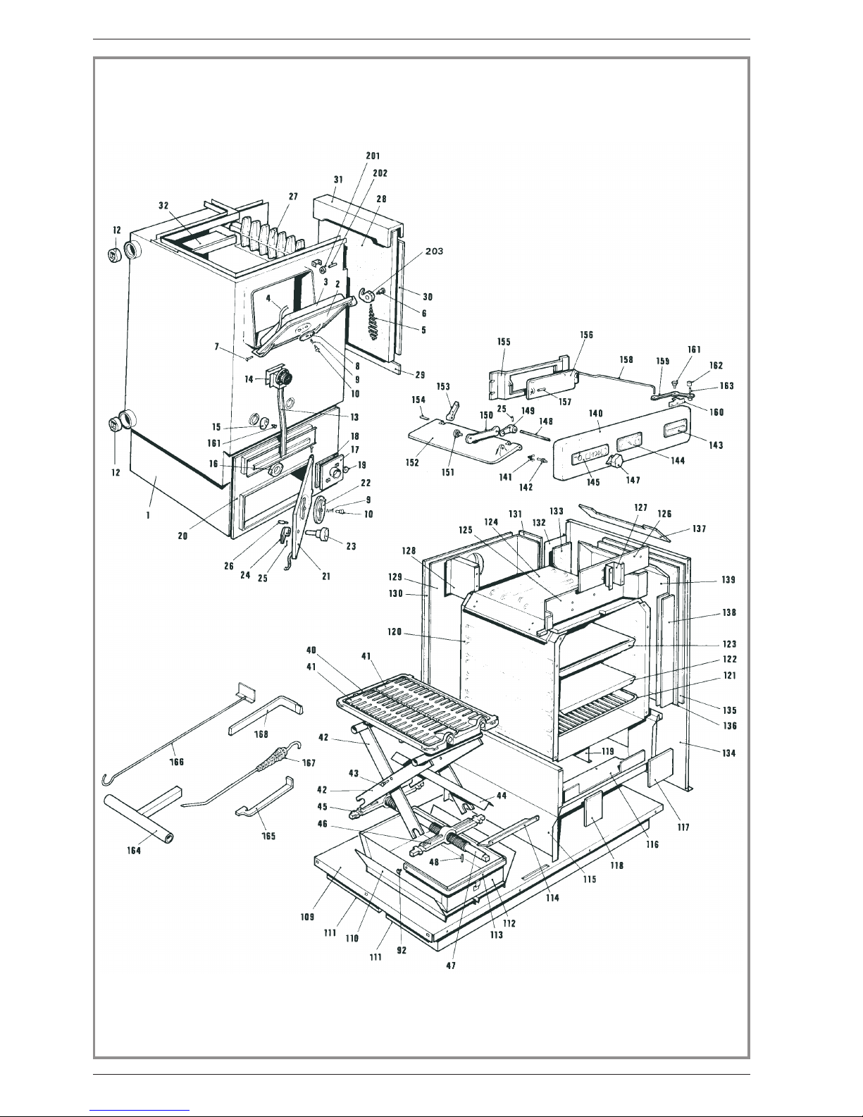
4. Spare parts
When ordering spare parts, specify the appliance type
and serial number, including the colour index (on the
guarantee or identification plate), the name of the part
and the part number.
Example : Cooker, ref : 82.914 A, Fr o n t p a n e l
652566 QV.
A = 82.914 A B = 82 914 B
C = 82 916 A D = 82 916 B
0 135090 ....Lubricantcompound..............................A.......B ......C.......D............1
1 911900 ....Waterjacket ..................................A.......B .............................1
1 911901 ....Waterjacket ..................................................C.......D ............1
2 309927 60 ..Maindoor....................................A....... B ...... C.......D ............1
2 981600 ....Maindoor....................................A....... B ...... C.......D ............ 1
3 314605 60 ..Innerpanel...................................A.......B ...... C.......D ............1
4 181602 ....Ceramicrope................ Ø8...............A....... B ......C.......D.......... 3,90m
5 158542 ....Handle .....................................A....... B ...... C.......D ............ 1
6 100954 ....Axle.......................................A....... B ......C.......D ............1
7 110402 ....Hingepin..................6x30...............A.......B ......C.......D............4
8 301713..60..Airdamper ...................................A.......B.......C.......D............1
9 166003 ....Spring................... 11x15 ..............A.......B ......C.......D............2
10 189103 ....Screw................... 27x8x6..............A....... B ...... C.......D ............ 2
13 179010 ....Thermostat...................................A.......B ...... C.......D ............1
14 261802 ....Heatshield...................................A.......B ...... C.......D ............1
15 320605 60 Slidingdoor....................................A.......B......C.......D............2
16 325301 60 ..Reducingplate.................................A.......B ...... C.......D ............1
17 305913 60 ..Accesscover..................................A.......B......C.......D............1
18 142335 ....Gasket .................105x105x3.............A.......B ...... C.......D ............1
19 105104 ....Nut .......................................A....... B .....C.......D............2
20 300806 60 ..Frame......................................A....... B......C.......D............ 1
21 301139 60 ..Ashpandoor.................................A.......B...... C.......D ............ 1
21 988801 ....Completedoor .................................A.......B ...... C.......D ............1
22 301711 60 ..Airdamper ...................................A.......B......C.......D............1
23 446300 ....Knob ......................................A.......B...... C.......D............1
24 301509 ....Doorlock....................................A.......B ......C.......D............ 1
25 134750 ....Pin .....................4x26...............A....... B ......C.......D ............ 2
26 100905 ....Axle.......................................A....... B ......C.......D............1
27 326700 ....Flueguard ...................................A....... B.............................1
27 326701 ....Flueguard ................................................... C.......D ............1
28 105221 ....Firebrick ....................................A.......B.............................1
30 157522 ....Insulatedplate.................................A.......B .............................1
31 321002 ....Firebrickfixation ................................A....... B.............................1
32 302726 ....Topplateshield ................................A.......B .............................1
40 319705 ....Gratesupport .................................A.......B ......C.......D ............1
41 306714 ....Oscillatinggrate ................................A....... B ...... C.......D ............2
42 867700.60..Crosspiece...................................A.......B.......C.......D............2
43 100951 ....Axle.......................................A....... B ......C.......D............2
44 208300 ....Screen.....................................A....... B.......C.......D ............1
45 922700 ....Castironnut ..................................A.......B ......C.......D............1
46 922701 ....Castironnut ..................................A.......B ......C.......D ............1
47 189114 ....Threadedliftingbar ..............................A....... B ...... C.......D ............ 1
48 134757 ....Pin .......................................A....... B ......C.......D ............2
50 302193 ....Topplate ....................................A.......B ...... C.......D ............1
50 702113..80.Topplate....................................A.......B.......C.......D............1
51 302414 ....Topplate ....................................A.......B ......C.......D............1
52 302524 ....Removabletopplate..............................A.......B ......C.......D ............ 1
53 302226 ....Removabletopplate..............................A.......B ......C.......D ............ 1
54 189118 ....Screw....................Ø10...............A....... B .....C.......D............1
55 303617 ....Topplate ....................................A.......B ......C.......D............1
56 30381960 ..Fluecollar ...................................A.......B ...... C.......D............1
57 303714 ....Blankingplate .................................A.......B ......C.......D............1
59 302604 ....Accesscover..................................A.......B ......C.......D ............1
60 211900 ....Clamp......................................A.......B ...... C.......D ............2
61 132750 ....Tighthingesupport ..............................A.......B ......C.......D ............3
62 132751 ....Hingesupport .................................A.......B ...... C.......D ............2
63 164558 ....Decorativrbar .................................A.......B ...... C.......D ............1
64 325002 60 ..Trimsupport ..................................A.......B ...... C.......D ............1
65 324902 60 ..Trimsupport ..................................A.......B ...... C.......D ............1
66 100940 ....Axle.......................................A....... B ...... C.......D ............ 4
67 273206 60 ..Hinge......................................A....... B ...... C.......D ............1
68 273406 60 ..Hinge......................................A....... B ...... C.......D ............1
69 273508 60 ..Hinge......................................A....... B ...... C.......D ............2
70 652566 45 ..Frontpanel...........................................B ...............D ............1
70 652566 QV..Frontpanel...................................A............... C.....................1
71 134304 ....Strikingplate..................................A.......B ...... C.......D ............2
72 122807 ....Nameplate...................................A.......B ...... C.......D ............1
73 158761 ....Handle .....................................A.......B ...... C.......D ............ 1
76 207833 25 ..R.sidepanel..................................A............... C.....................1
76 207833 30 ..R.sidepanel..........................................B ...............D ............1
77 228000 ....Square .....................................A.......B ...... C.......D ............4
78 207755 25 ..L.sidepanel ..................................A............... C.....................1
78 207755 30 ..L.sidepanel ..........................................B ...............D ............ 1
79 208802 ....Innerpanel...................................A....... B ...... C.......D ............ 1
80 204145 ....Backpanel ...................................A.......B ......C.......D............1
81 237402 ....Reducingplate.................................A....... B ...... C.......D ............ 2
N° Code ....Description ................Type..............A.......B ...... C.......D ...........
Document n° 66-5EN ~ 18/01/1999
82 914 - 82 916 Diva - "La Premiere" Central heating cooking
Technical manual 51

Document n° 66-5EN ~ 18/01/1999
Central heating cooking Diva - "La Premiere" 82 914 - 82 916
52 Technical manual

82 204201 ....Supplementary.plate..............................A....... B......C.......D.............. 1
83200331 20 ..Frontplate...................................A.......B......C.......D ............1
84 228904 60 ..Square .....................................A.......B ......C.......D ............1
85 101013 ....Magneticcatch.................................A.......B ......C.......D ............ 2
86 266602 20 ..Accesscover..................................A....... B......C.......D ............. 1
87 427001 ....Gasket.....................................A....... B......C.......D.............. 1
88105118 ....Nut ......................................A.......B .....C.......D ............2
89 190004 ....Captivescrew.................................A.......B......C........D.............2
90.200707 20 ..Innerfrontpanel ................................A.......B......C.......D ............1
91 236106 20 ..Sealingplate..................................A.......B......C.......D ............1
92 100902 ....Axle.......................................A....... B ...... C.......D ............6
93 647519 28 ..Ovenpanel...................................A............... C.....................1
93 647519 30 ..Ovenpanel...........................................B...............D ............1
94 647614 20 ..Innerpanel ...................................A....... B...... C.......D ............ 1
95 124454 ....Strut.......................................A.......B ......C.......D ............ 2
96 158760 ....Handle .....................................A....... B ...... C.......D ............1
97 137155 ....Refractoryglass ................................A....... B...... C.......D ............1
98 137154 ....Glass ......................................A....... B ...... C.......D ............ 1
99 142303 ....Joint.......................................A.......B...... C.......D ..........1,45m
100 142306 ....Adhesiverope...................................A....... B ...... C.......D .......... 0,64m
101 109847 ....Hinge......................................A.......B ...... C.......D ............2
102 109844 ....Hinge......................................A.......B ......C.......D ............2
103 249100 28 ..Warmingdrawerpanel.............................A............... C.....................1
103 249100 30 ..Warmingdrawerpanel.....................................B ...............D ............ 1
104 249200 10 ..Innerpanel...................................A.......B ...... C.......D ............1
105 105501 ....Blockstop...................................A.......B ...... C.......D ............ 2
106 158603 ....Handle .....................................A....... B ...... C.......D ............1
107 909814 ....Hinge......................................A.......B ......C.......D............2
108 451009 ....Stiffeningplate.................................A....... B...... C.......D ............2
109 200114 ....Base ......................................A.......B ...... C.......D ............ 1
110 202301 ....Ashpanguide .................................A....... B ......C.......D ............2
111 200422 10..Plinth ......................................A....... B......C.......D ............2
112 624029 ....Ash-pan.....................................A....... B...... C.......D ............1
113 400207 60 ..Ashpanhandle ................................A.......B ...... C.......D ............1
114 232804 ....Ashguide....................................A.......B ......C.......D ............1
115 639000 ....Warmingdrawertop..............................A.......B ......C.......D............1
116 233008 ....Sootguide ...................................A.......B......C.......D ............1
117 446205 ....Protectionplate.................................A.......B ......C.......D............1
118 446206 ....Protectionplate.................................A.......B ......C.......D............1
119 222505 ....Fluebaffle...................................A.......B.......C.......D............1
120691021 20 ..Oven ......................................A.......B......C.......D ............1
121 134915 ....Wirerack....................................A.......B ......C.......D............1
122 218805 ....Bakingtray...................................A.......B ......C.......D ............1
123 21890420...Bakingdish...................................A.......B.......C.......D............1
124 308881.....Oventop....................................A.......B.......C.......D............1
125 313807 ....Supplementarypanel..............................A.......B.......C.......D............1
126 446207 ....Protectionplate.................................A.......B.......C.......D............ 1
127 209700 ....Screen .....................................A....... B ......C.......D............1
128 205503 ....Strut.......................................A.......B ......C.......D............1
129 208403 ....Heatshield...................................A.......B ......C.......D............1
130 446200 ....Protectionplate ................................A.......B ...... C.......D
131 446201 ....Protectionplate................................A.......B........C.......D............ 1
132 607500.....Ovenbackpanel................................A.......B.......C.......D............1
133 446203 ....Protectionplate ................................A.......B ......C.......D............1
134 608700 ....Innerpanel...................................A.......B.......C.......D............1
135 208104 ....Heatshield...................................A................C.......D............1
136.446202 ....Protectionplate ................................A....... B ......C.......D............ 1
137 446208 ....Protectionplate ................................A.......B ......C.......D............1
138 446204 ....Protectionplate ................................A.......B ......C.......D............1
139 209305 ....Suppl.heatshield ...............................A....... B ...... C.......D ............1
140 653381 30 ..Toppanel............................................B ...............D ............1
140 653381 35 ..Toppanel....................................A............... C.....................1
141 100602 ....Snapclip ....................................A....... B.......C.......D............4
142 134505 ....Pushclip ....................................A....... B.......C.......D............4
143 123461 ....Trim.......................................A....... B ......C.......D............ 1
144 178607 ....Thermometer..................................A.......B.......C.......D............1
145 177034 ....Dashboard...................................A.......B .....C.......D............1
147 105114 ....Knob......................................A.......B........C.......D............1
148 460007 ....Regulatorshaft.................................A....... B.......C.......D............ 1
149 301288 ....Drivingbar ...................................A.......B ......C.......D............1
150 324602 ....Drivingbar ...................................A.......B ......C.......D............1
151 100943 ....Bolt .......................................A....... B.......C.......D............2
152 325701 ....Fluedoor....................................A....... B ......C.......D............1
153 313301 ....Hinge......................................A.......B ......C.......D............2
154 400012 ....Axle.......................................A.......B ......C.......D............2
155 304509 ....Frame......................................A.......B ......C.......D............1
156 304615 ....Directdraughtdoor ..............................A.......B ......C.......D............1
157 134702 ....Pin .....................5x32...............A.......B ......C.......D............2
158 462415 ....Directdraughtrod ...............................A....... B.......C.......D ............ 1
159 23690560...Drivingbar ...................................A.......B.......C.......D............1
160 231301 ....Square .....................................A.......B ...... C.......D ............1
161 100939 ....Axle.......................................A.......B.......C.......D............3
162 105115 ....Knob ......................................A.......B......C.......D ............2
163 179911 ....Threadrod ...................................A.......B ......C.......D............2
164 813100 60....Liftinghandle..................................A........B...... C.......D............1
165 312803 60 ..Handtool....................................A.......B.......C.......D............1
166 858003 60 ..Scraper.....................................A.......B ...... C.......D ............1
167 180002 ....Poker......................................A....... B ......C.......D ............1
Document n° 66-5EN ~ 18/01/1999
82 914 - 82 916 Diva - "La Premiere" Central heating cooking
Technical manual 53
.
Document n° 66-5EN ~ 18/01/1999
Central heating cooking Diva - "La Premiere" 82 914 - 82 916
54 Technical manual

Document n° 66-5EN ~ 18/01/1999
82 914 - 82 916 Diva - "La Premiere" Central heating cooking
Technical manual 55
.
.
172 905103 ....Halfboxwithwheel ..............................A.......B ...... C.......D ............1
173 326001 91 ..Halfbox.....................................A.......B ...... C.......D ............1
174 652604 25 ..Cover......................................A............... C.....................1
174 652604 30 ..Cover.............................................. B ...............D ............ 1
175 254520 20 ..Supplementarycover .............................A....... B ...... C.......D ........... 2/1
176 652738 25 ..Cover......................................A............... C.....................1
176 652738.30..Cover.............................................. B...............D.............1
177 652605 25 ..Cover......................................A............... C.....................1
177 652605 30 ..Cover..............................................B...............D ............ 1
178 254701 20 ..Innercover..................................A.......B......C.......D ............1
179 252801 25 ..Cover......................................A............... C.....................1
179 252801 30 ..Cover..............................................B...............D ............ 1
180 254801.20..Innercover...................................A.......B......C.......D..............1
181 158540 ....Handle .....................................A....... B ...... C.......D ........... 3/2
182 109826 ....Hinge......................................A.......B ...... C.......D ............2
183 109825 ....Hinge......................................A.......B ......C.......D............2
184 109824 ....Hinge......................................A.......B ......C.......D ............2
185 122303 ....Capnut .....................................A....... B ......C.......D............4
186 189108 ....Screw.................... 5X8...............A.......B ......C.......D ............4
201 134252 ....Bushing.....................................A.......B ......C.......D............1
202 134701 ....Pin .....................5x24...............A....... B ......C.......D ............ 1
203 301518 60 ..Doorlock....................................A.......B ...... C.......D ............1
168 154801 ....Operatingtool .................................A....... B ...... C.......D ............ 1
170 30150660..Doorlock.....................................A.......B......C.......D............2
171301731 91 ..Airdamper ...................................A.......B......C.......D ............1
Warranty certificate
*
Nameandaddressofinstaller:_____________________________________________
________________________________________________________________
(
Telephone:_______________________
*
Name and address of customer :
________________________________________________________________
________________________________________________________________
Date of installation :
___ ___ / ___ ___ / ___ ___ ___ ___
Model of the appliance :q82 914 82 916
Couleur : A B
N° de sé rie / Serial number :
___ ___ ___ ___ ___ ___
This certificate has to be completed and kept carefully.
In case of claims, send a copy of this to :
Table of contents


