Dixie DN720P User manual

Coca-Cola Chameleon Vender & Lean Marketing Vender
P Series Chameleon P Series LMV
Model DN504P and 720P
Beginning Production Run 7675AE
Manufactured by
Dixie-Narco, Inc.
P.O. Drawer 719
Williston, SC 29853-0719
803-266-5001
fax: 803-266-5049
Visit us on the web: www.dixienarco.com
Part #803,904,540.01

Page 2 of 100
Table of Contents
GENERAL INFORMATION
Application ........................................................................................................................................ 4
Vender Safety Precautions ............................................................................................................... 4
Product Identification ........................................................................................................................ 4
Physical Characteristics.................................................................................................................... 4
A INSTALLATION & SETUP
Unpacking the Vender ...................................................................................................................... 5
Electric Power Requirements............................................................................................................ 5
Power Supply and Grounding Requirements................................................................................ 5- 6
Placing the Vender on Location........................................................................................................ 6
Level the Vender............................................................................................................................... 6
Space the Vender........................................................................................................................6 - 7
Coin Changers and Other Accessories.............................................................................................7
Loading the Change Tubes............................................................................................................... 7
Loading Product................................................................................................................................ 7
Initial Loading.................................................................................................................................... 7
B PROGRAMMING........................................................................................................................ 8 -28
Quick Reference Prompts............................................................................................................... 29
Set Vender Type............................................................................................................................. 30
Default Space to Sales Setting ..................................................................................................31-32
C GENERAL MAINTENANCE
Power.............................................................................................................................................. 33
Cleaning.......................................................................................................................................... 33
Refrigeration Condenser................................................................................................................. 33
Coin Acceptor ................................................................................................................................. 33
Lubricating the Vender.................................................................................................................... 33
EPROM Replacement..............................................................................................................34 - 35
D MAJOR COMPONENT DESCRIPTION
Electrical ......................................................................................................................................... 36
Refrigeration ................................................................................................................................... 36
Motor / Encoder…………………………………………………………………………………………….. 36
SBC Control Board ......................................................................................................................... 37
E TROUBLESHOOTING FLOWCHARTS
All Coins are Rejected .................................................................................................................... 38
All Bills are Rejected....................................................................................................................... 39
Incorrect Change Dispensed........................................................................................................... 40
Selection Will Not Vend .................................................................................................................. 41
Ice / Frost on Evaporator ................................................................................................................ 42
Compressor Runs Continuously ..................................................................................................... 42
Compressor Will Not Start............................................................................................................... 43
Machine Not Cooling....................................................................................................................... 44
Can’t Enter the Menu or Diagnostics .............................................................................................. 45
Lights Are Not On ........................................................................................................................... 46
One or Motors Run When The Main Door Is Closed....................................................................... 47
Sold Out.......................................................................................................................................... 48
The Display is Dead........................................................................................................................ 49
Can’t Read the Display................................................................................................................... 50

Page 3 of 100
Table of Contents
F WIRING DIAGRAMS AND SCHEMATICS
Figure 1 – Chameleon Wiring Diagram .......................................................................................... 51
Figure 2 – LMV Wiring Diagram…………………………………………………………………………...52
Figure 3 – Compressor Wiring Diagram.......................................................................................... 53
G PARTS LIST 54
MAIN DOOR EXTERIOR........................................................................................................... 55-59
MAIN DOOR INTERIOR (A) ...................................................................................................... 60-63
MAIN DOOR INTERIOR (B)……………………………………………………………………………64-67
SELECT PANEL........................................................................................................................68-70
T8 LIGHTING.............................................................................................................................71-73
ELECTRONIC COMPONENTS................................................................................................. 74-75
INNER DOOR............................................................................................................................76-77
HARNESSING ..........................................................................................................................78-79
POWER DISTRIBUTION BOX................................................................................................... 80-82
CABINET AND VEND MECHANISM (SECTION 1)................................................................... 83-85
CABINET AND VEND MECHANISM (SECTION 2)................................................................... 86-87
CHUTE ASSEMBLY ..................................................................................................................88-89
EVAPORATOR FAN HOUSING................................................................................................90-91
REFRIGERATION .....................................................................................................................92-94
MISCELLANEOUS LABELS........................................................................................................... 95
SCREWS & NUTS.....................................................................................................................96-97
WASHERS, BOLTS, & MISC. HARDWARE............................................................................ 98-100

Page 4 of 100
APPLICATION
This information applies to 504 and 720P-Series
venders manufactured the first quarter 2006 which
have significant differences in programming and
parts content from previous venders. To order parts
or information pertaining to this vender, please
contact Dixie Narco.
VENDER SAFETY PRECAUTIONS
Please read this manual in its entirety. This service
information is intended for use by a qualified service
technician, who is familiar with proper and safe
procedures to be followed when repairing, replacing,
or adjusting any Dixie-Narco vender components.
All repairs should be performed by a qualified
service technician who is equipped with the proper
tools and replacement components, using Genuine
Dixie-Narco Factory Parts.
REPAIRS AND/OR SERVICING
ATTEMPTED BY UNINFORMED
PERSONS CAN RESULT IN
HAZARDS DEVELOPING DUE TO
IMPROPER ASSEMBLY OR
ADJUSTMENTS WHILE
PERFORMING SUCH REPAIRS.
PERSONS NOT HAVING A PROPER
BACKGROUND MAY SUBJECT
THEMSELVES TO THE RISK OF
INJURY OR ELECTRICAL SHOCK
WHICH CAN BE SERIOUS OR EVEN
FATAL.
PRODUCT IDENTIFICATION
First production of 504 and 720 P-Series was March
2006.
The production date of Dixie-Narco products is
determined by the date code incorporated in the
serial number.
The vender serial number takes the form yyyyzz-
xxxx.The last 4 digits (xxxx) identify the specific
vender. The first 4 digits (yyyy) identify the
manufacturing run that the vender was built in. The
two alpha characters (zz) identify the quarter and the
year the vender was built. The first alpha-character
identifies the quarter.
A = 1st quarter
B = 2nd quarter
C = 3rd quarter
D = 4th quarter
The second alpha-character identifies the year:
E = 2006
F = 2007
G = 2008
H = 2009
I = 2010
J = 2011
PHYSICAL CHARACTERISTICS
720P 504P
HEIGHT 72” 72”
WIDTH 37” 28”
DEPTH 34” 33.5”
DEPTH WITH
VALIDATOR N/A N/A
SHIPPING WEIGHT 788lbs 678 lbs.
Loaded Weight 4 Deep
Cans 1512lbs 1153 lbs
Model Number of
Selections Number of Narrow
Columns
504P
LMV 8 7
720P
LMV 8 10
504P
CCC 6 7
720P
CCC 8 10
RECEIVING INSPECTION
Upon receipt, inspect the vender for any shipping
damage. If there is any damage have the driver
note the damage on the bill of lading and notify
Dixie-Narco.
Although the terms of sale are FOB shipping point,
which requires the consignee to originate shipping
damage claims, Dixie-Narco will gladly help if you
must file a claim.

Page 5 of 100
The Dixie-Narco P Series vender is designed
utilizing the latest technology.
UNPACKING THE VENDERS
Remove the stretch wrap and top cover from the
vender. Product cards are installed in the select
buttons.
DO NOT STORE THE VENDER
OUTSIDE WITH THE STRETCH
WRAP ON. THIS COULD CAUSE
THE STRETCH WRAP TO BOND
TO THE VENDER’S SURFACE,
WHICH COULD DAMAGE THE
FINISH.
Remove the shipping boards from the bottom of the
vender. The shipping boards are attached by the
leveling legs. To avoid unnecessary damage to the
leveling legs or base, remove the shipping boards by
using a 1½” “socket type” wrench to unscrew the
leveling legs. Be sure to replace the legs after
removing the shipping boards.
WARNING
TO AVOID THE POSSIBILITY OF A
FIRE HAZARD, DO NOT STORE
ANYTHING OR ALLOW DEBRIS OF
ANY KIND TO ACCUMULATE IN
THE BOTTOM OF THE DOOR, IN
AND AROUND THE
REFRIGERATION COMPARTMENT
OF THE CABINET, OR IN FRONT
OF THE EVAPORATOR AND
CONDENSER COILS.
WARNING: ENSURE THAT
POWER IS DISCONNECTED
FROM THE VENDER OR
THAT THE POWER
INTERRUPT SWITCH IS NOT
DEFEATED BEFORE
INSPECTING OR REPLACING
THE LAMPS, OTHER
ELECTRICAL COMPONENTS,
OR WORKING WITH OR
ADJUSTING THE VENDING
MECHANISM. FAILURE TO
COMPLY WITH THESE
INSTRUCTIONS MAY SUBJECT
THE USER TO THE RISK OF
ELECTRICAL SHOCK OR
MECHANICAL INJURY, WHICH
CAN BE SERIOUS OR FATAL.
ELECTRIC POWER NEEDED
Refer to the cabinet serial number plate to determine
the proper voltage and frequency the machine
requires (domestically this requirement is 120 Volts,
60 Hertz). The cabinet serial plate also indicates the
Amperage of the vender. The vender must be
plugged into a properly rated, single phase
alternating current outlet with its own circuit
protection (fuse / circuit breaker).
DO NOT USE AN EXTENSION CORD.
POWER SUPPLY CORD and
GROUNDING REQUIREMENTS
In accordance with the National Electrical Code and
Underwriters Laboratories Inc., beginning April 10,
2006 all domestic vending machines are equipped
with a three-wire power supply cord and Ground
Fault Circuit Interrupter (GFCI). The GFCI device
is provided as part of the power supply cord and is
either incorporated directly into the plug or mounted
on the cord adjacent to the plug.
WARNING
•The GFCI protects against current
leakage caused by ground faults.
The GFCI is not designed to
protect against over current or
short circuits.
•DO NOT use the TEST and
RESET buttons on the GFCI as an
ON/OFF switch.
•The vending machine supply cord
MUST be plugged directly into a
properly grounded, 3 wire
receptacle that is properly
protected by a fuse or circuit
breaker. If the receptacle will not
accept the power cord plug, it must
be replaced with a properly
grounded, 3 wire receptacle in
accordance with the National
Electrical Code and Local Codes
and Ordinances. The work should
be done by a qualified electrician.
DO NOT USE A 3 WIRE TO 2
WIRE ADAPTOR

Page 6 of 100
DO NOT REMOVE THE
GROUND PIN ON THE PLUG OR
IN ANY WAY BYPASS, MODIFY,
DEFEAT, OR DESTROY THE
GROUNDING SYSTEM OF THE
VENDING MACHINE
•DO NOT USE WITH AN EXTENSION
CORD.
•DO NOT REMOVE THE WARNING TAG
ATTACHED TO THE POWER SUPPLY
CORD.
•The GFCI must be tested frequently and before
each use in accordance with the instructions
provided on the GFCI device. IF THE GFCI
DOES NOT PASS THE TEST, DO NOT USE
THE MACHINE. Unplug the supply cord
from the receptacle and call the Dixie-Narco
Technical Support Group for assistance at 1-
800-688-9090.
It is recommended that the machine be located so
that the GFCI device will be accessible after the
machine is installed. After installation, visually
inspect the GFCI and power supply cord to be sure it
is not crushed, pinched, or stretched.
Protect the power supply cord during transportation
and use. Periodically inspect the power supply cord
for damage. If the cord or plug is worn or damaged,
it must be replaced with a power supply cord of the
same type, size and specification as originally
provided with the machine. DO NOT USE THE
VENDING MACHINE UNTIL THE WORN OR
DAMAGED CORD IS REPLACED.
FAILURE TO COMPLY WITH
THESE INSTRUCTIONS MAY
SUBJECT A SERVICE PERSON
OR USER TO THE RISK OF
INJURY OR ELECTRICAL
SHOCK WHICH CAN BE
SERIOUS OR FATAL.
PLACING THE VENDER ON LOCATION
!! CAUTION !!
DO NOT TRANSPORT THE
VENDER TO OR FROM THE
LOCATION LOADED WITH
PRODUCT.
DAMAGE TO THE VENDER MAY
RESULT.
The vender must be located on a solid, flat, and
level surface. Ensure the flooring can bear the
weight of a fully loaded vender (approx. 1200 lbs).
The vender must be positioned close enough to an
electrical outlet that an extension cord is not
required. If the machine will be subject to user
misuse or vandalism, it is recommended that the
vender be secured to the floor or wall as described
in Dixie-Narco Technical Bulletin 344. Call the Dixie-
Narco Technical Service Department or your Dixie-
Narco Representative for assistance.
LEVEL THE VENDER
When the vender is level, the door can be opened to
any position and it will not move by itself. Open the
door to several different positions before deciding
the vender is level. A carpenter’s level will help
verify the machine is level.
Make sure that all leveling legs are in contact with
the floor. If you cannot level the vender in its current
location, select another location. DO NOT place any
objects under the machine.
This Machine is not suitable for installation in an
area where a water jet may be used.
DANGER
THE VENDER MUST BE
PROPERLY LOCATED AND
LEVELED. IF THE MACHINE WILL
BE SUBJECT TO USER MISUSE
OR VANDALISM IT IS
RECOMMENDED THAT THE
VENDER BE SECURED TO THE
FLOOR OR WALL AS DESCRIBED
IN DIXIE-NARCO TECHNICAL
BULLETIN 344 TO MINIMIZE THE
RISK OF INJURY OR DEATH
FROM TIPPING. CALL THE DIXIE-
NARCO TECHNICAL SERVICE
DEPARTMENT OR YOUR DIXIE-
NARCO REPRESENTATIVE FOR
ASSISTANCE.
SPACE THE VENDER
Do not block the rear of the vender. Keep the vender 4
inches (10 cm) from the wall to ensure adequate airflow to
the condenser and compressor. At the front of the vender,
make sure that nothing obstructs the air intake at the
bottom of the main door. At the rear of the vender, make
sure nothing obstructs the air exhaust at the bottom of the
cabinet.

Page 7 of 100
WARNING
TO AVOID THE POSSIBILITY OF A
FIRE HAZARD, DO NOT STORE
ANYTHING OR ALLOW DEBRIS OF
ANY KIND TO ACCUMULATE IN
THE BOTTOM OF THE DOOR, IN
AND AROUND THE
REFRIGERATION COMPARTMENT
OF THE CABINET, OR IN FRONT
OF THE EVAPORATOR AND
CONDENSER COILS.
COIN CHANGERS & OTHER
ACCESSORIES
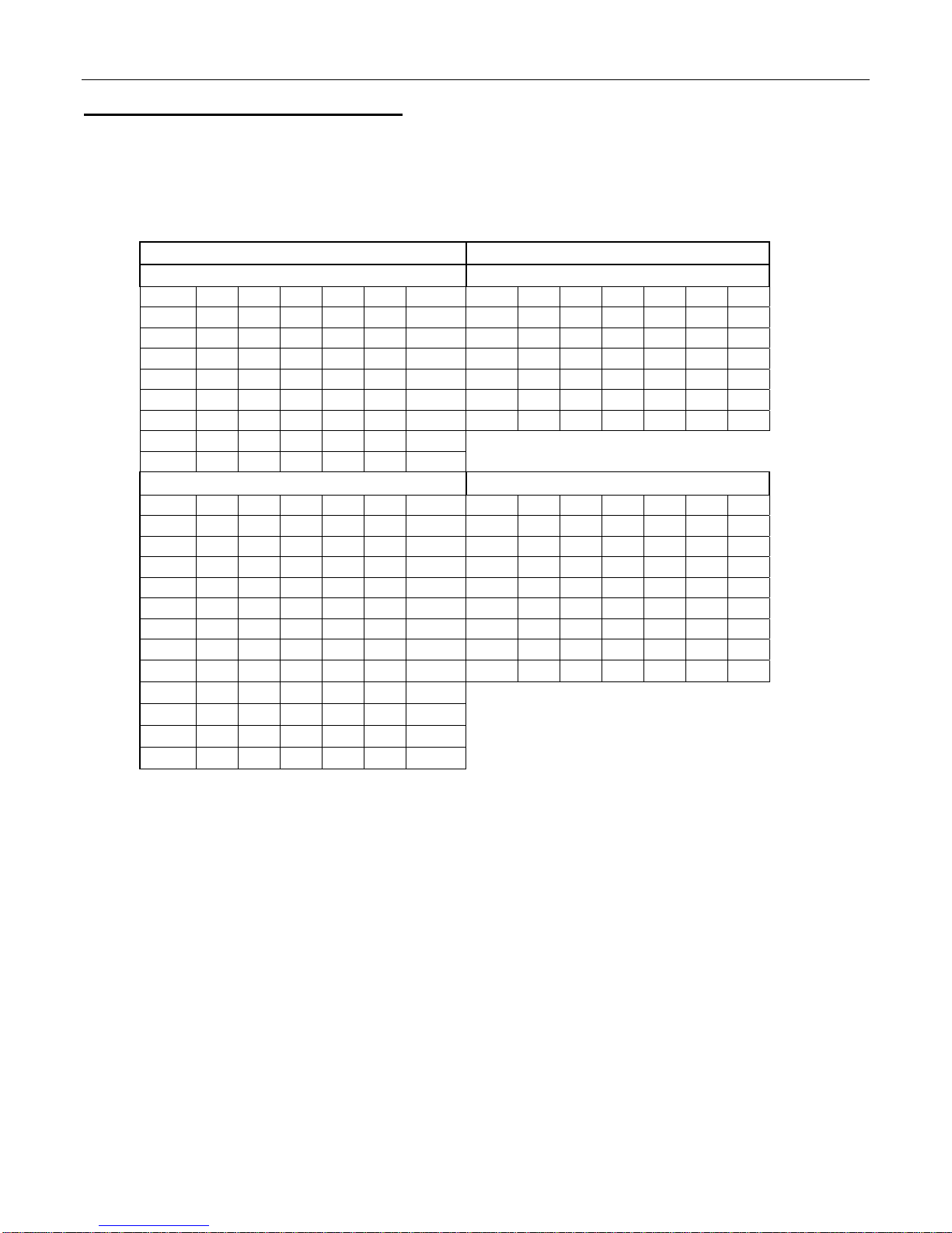
The vender must have an MDB coin changer
installed and can have an MDB bill acceptor
installed. If the MDB coin changer and other MDB
accessories are not factory installed, refer to the
instructions received from the manufacturer of the
MDB coin changer and other MDB accessories for
proper set-up and installation.
The vender will support the following MDB coin
changers:
Multi-Drop Coin Mech (Domestic)
Coinco 9302GX
Coinco USQ G700 Series
Conlux USLZ-101
Conlux CCM5G
Mars 4510
Mars 6512
The vender will support the following MDB bill
validators:
Multi-Drop Bill Validators (Domestic)
Coinco BA30B, BA50, MAG30, MAG50
Mars VN2512, VN2502, VN2312
Conlux NBU-2111-12, NBM 3000 Series
Ardac 5500 Series
The vender will support the following MDB card
readers:
At publication, card reader dispositions were
not available. Contact card reader
manufacturer for proper installation and
setup.
LOADING CHANGE TUBES
Open the main door and enter the “TUFL” TUBE
FILL ROUTINE mode in Programming (see Section
B – Programming).
Load the coin mechanism with coins by inserting
coins in the coin mech’s separator. The display will
show the total number of the coin type as they are
inserted.
Note: A low coin level in the coin tubes will
interfere with operation of the bill validator.
For additional information about coin mechanisms,
refer to the specific manufacturer’s instructions.
Loading Product
The P Series Vender is designed to vend a wide
range of packages internationally.
All P Series Venders are shipped ready to vend
packages according to customers orders. To vend
an alternative package in the P Series vender,
contact Dixie Narco Technical Service Dept. or your
Representative for assistance. You can also search
the package type you wish to vend at
www.dixienarco.com.
INITIAL LOADING
To ensure proper vending, make sure columns are
set to vend the proper packages. When loading the
narrow columns, lay the first row of packages on the
Load Bar.
Correct loading will prevent service calls and ensure
proper vending.
After loading the vender for the first time, ensure the
vender is loaded and primed. Priming is done in
programming. The depth must also be
programmed depending on the package to be
vended. 12oz Cans may be programmed up to 4
deep.
NOTE: To ensure proper airflow through the
evaporator and the proper operation of the
Vend Sensor, DO NOT place packages (or
other foreign objects) in the bottom of the
tank.
SERVICE NOTE
Battery Backup (SBC)
The Single Board Controller is equipped with a battery
backup which is used to retain information programmed in
the system (pricing, time, date, etc.) in case of power
interruptions or any time the main power is off. When the
vender is shipped, the battery is connected and memory is
being maintained.
Disconnect the battery if the vender will be stored for a
long period of time. The following steps will guide you
through this procedure.
¾Remove power from the vender by unplugging
the main power cord from the wall receptacle.
¾Locate the Control Board on the main door.
Remove the battery from its holder (B1).

PROGRAMMING P SERIES
Page 8 of 100
COCA-COLA EVS REVISION 3.0 P SERIES PROGRAMMING METHOD
August 2003
LMV CHAMELEON (CCC)
The controller has two modes of operation: SALES and SERVICE.
SALES MODE:
In sales mode, on power up display will show software installed in vender, then change to POS message or decimal point.
Note: If ”COLS” appears on the display on power up with the door open, you will need to program the vender model number
in the controller. To program with “COLS” on the display press select button 4. The display will show “6” for six columns.
Press select button 2 to scroll through available number of columns in the machine. When the displayed number of columns
matches the number of columns in the machine, press select button 4 to set the number of columns. “MODL” will appear on
the display, press select button 4. The display will show the first available model number for the current vender type. Press
select button 2 to scroll through the available vender model numbers for this vender. When the vender type you wish to save
is showing on the display, press select button 4. The display will scroll “4 = SET PACKAGE TYPE 1 = EXIT” . Press select
button 4 and the display will show “ALL1” with the 1 flashing. This will allow you to set the package type of the machine if it is
different that the default of package type 2. Press select button 2 to scroll through the available package types. Press select
button 4 to set the displayed package type, and the display will show “SAVE”. Press button 4 to save the package type.
“PRM1” will appear on the display. Press button 4 to prime column 1 or select button 1 to skip priming column 1. The display
will then display “PRM2” . Repeat the priming process until all columns have been primed or skipped. The controller will return
to normal door open operating mode. The far right decimal also being lit indicates column(s) is (are) - jammed or select
switch(es) are stuck. When money is inserted, the display indicates the total amount of the deposit. The select buttons are
used to select the product. In sales mode you may access an external menu for reading historical sales counters, cash
counters, error codes, or return to sales mode.
SERVICE MODE:
If configuration switch 4 is set to "C4 0", when the door is opened, "NONE" or a list of Error codes will show on
the display. If configuration switch 4 is set to "C4 1", when the door is opened, "CASH ####-##.##", "SALE
####-####", "CARD ####-####", "EROR", or "NONE" will show on the display. The service mode is entered
when the door is open and the service switch on the controller is pressed. The operator can now use the first four
select switches to move through the main routine menu.
Select Button 1: Abort/Cancel - will return to previous menu prompt.
Select Button 2: Scroll Up - forward in menu.
Select Button 3: Scroll Down - backward in menu.
Select Button 4: Enter/Save/Clear - Allows you to enter a specific routine, save what you have programmed, or
clear the error prompts.
Note: Routines with *are password protected. They can only be viewed and entered after the password is entered at the
"PASS" prompt.
EXTERNAL MENU MODE:
The information available in this mode is obtainable with the door closed or open as long as the vender is in sales
mode, by entering the password which is set at 4,2,3,1. Information available is historical cash counted,
resettable cash counted for each selection, historical sale (total number of vends), resettable vends counted for
each selection, error codes, and return. Refer to the "CASH", "SALE", AND "EROR" routines for instructions to
move through the menus.
9 10 11 12
1
2
3
4
5
6
7
8
1
2
3
4
5
6

PROGRAMMING P SERIES
Page 9 of 100
PROGRAMMING MENU
"EROR" - ERROR ROUTINE
This function allows you to enter the error readout routine. “EROR” will appear when you press the service button on
the control board. Press select button 4, if there have been no errors since the last reset, the display will read
"NONE". If one or more errors have occurred, the display will show the first error code that occurred.
The following are error codes that may be displayed and detailed information accessed: NONE, VEND, CTRL, SEL,
STS, CHAR, BUAL, CRDR, S-D, and RFRG.
Press select button 2 or 3 to scroll through any error codes that are present.
Important: If there is only one problem, that will be the only error code shown when you enter the error code
sub-menus.
With an error code showing on the display, press select button 4 to access detailed information.
With an error code showing on the display, press and hold select button 4 for 2 seconds, will clear the error.
Press select button 1 to return to "EROR".
"VEND" - Vend Mechanism Summary Errors
Press select button 4 and the display will show one of the following:
-"CJ#", where # is the column number detected jammed.
-“CS”, chute sensor failure.
-“HS”, home sense error.
Press select button 1 will return to "VEND" if all vend mech errors have not been cleared.
If all vend mech errors have been cleared the next error mode will be displayed, or "NONE" if there
are no errors.
Press select button 1 will return to "EROR".
"CTRL" - Control System Summary Errors
Press select button 4 and the display will show one of the following:
-"DS", indicating a door switch in the open position for more than 1 hour.
-"RAM", indicating the check sum for service mode settings memory has been corrupted.
-"ACLO", indicating AC supply to the machine has fallen more than 15% below normal line
voltage for more than 30 seconds.
-"SF", indicating a peripheral has introduced a scaling factor that is incompatible with current
setting.
Press select button 1 will return to "CTRL" if all control system errors have not been cleared.
If all control system errors have been cleared the next error code will be displayed, or "NONE" if
there are no errors.
Press select button 1 will return to "EROR".
"SEL" - Select Switch Summary Errors
Press select button 4 and the display will show "SL##", indicating a select switch has been active for
more than 15 seconds while in normal (sales) mode.
Press select button 1 will return to "SEL" if all select switch errors have not been cleared.
If all select switch errors have been cleared the next error code will be displayed or "NONE" if there
are no errors.
Press select button 1 will return to "EROR".
"STS" - Space To Sales Summary Errors
Press select button 4 and the display will show "UA##", indicating a column not assigned to a select
button.
Press select button 1 will return to "STS" if all space-to-sales errors have not been cleared.
If all space-to-sales errors have been cleared the next error code will be displayed, or "NONE" if
there are no errors.
Press select button 1 will return to "EROR".

PROGRAMMING P SERIES
Page 10 of 100
"CHAR" - Changer Summary Errors
Press select button 4 and the display will show one of the following:
-"CC", indicating a changer communication error. (No communication for more than 2
seconds)
-"TS", indicating a tube sensor error.
-"IC", indicating an inlet chute blocked error (no coins sensed in acceptor for 96 hours).
-"TJ##", indicating a tube jam error.
-"CRCH", indicating a changer ROM check sum error (failed changer).
-"EE", indicating excessive escrow attempts (more than 255 since last coin sensed).
-"NJ", indicating a coin jam reported by coin mech.
-"LA", indicating a low coin acceptance rate (less than 80%).
-"DIS", indicating an acceptor is unplugged.
-"ROUT", indicating a coin was misrouted.
Press select button 1 will return to "CHAR" if all changer errors have not been cleared.
If all changer errors have been cleared the next error code will be displayed or "NONE" if there are
no errors.
Press select button 1 will return to "EROR".
"BUAL" - Bill Validator Summary Errors
Press select button 4 and the display will show one of the following:
-"BC", indicating a bill validator communication error. (No communication for more than 5
seconds)
-"BFUL", indicating the bill stacker is full.
-"BILL", indicating a defective motor in the validator.
-"BJ", indicating a bill jam in the validator.
-"BRCH", indicating a check sum error.
-"BOPN", indicating an open stacker.
-"BS", indicating a bill validator sensor error.
Press select button 1 will return to "BUAL" if all changer errors have not been cleared.
If all validator errors have been cleared the next error code will be displayed or "NONE" if there are
no errors.
Press select button 1 will return to "EROR".
"CRDR" - Card Reader Summary Errors
Press select button 4 and the display will show one of the following:
-"CRC", indicating no card reader communication for 5 seconds.
-"CRXY", indicating the most recent "non-transient error" from the card reader (failed card
reader).
Press select button 1 will return to "CRDR" if all changer errors have not been cleared.
If all card reader errors have been cleared the next error code will be displayed or "NONE" if there
are no errors.
Press select button 1 will return to "EROR".
Press select button 2 will scroll to the next routine.
"S-D" – Display Device Summary Errors
Press select button 4 and the display will show one of the following:
-"SDC", indicating no display device communication for 5 seconds.
-"SDXX", error code number “XX”.
Press select button 1 will return to "S-D" if all display device errors have not been cleared.
If all display device errors have been cleared the next error code will be displayed or "NONE" if there
are no errors.
Press select button 1 will return to "EROR".
Press select button 2 will scroll to the next routine.

PROGRAMMING P SERIES
Page 11 of 100
"RFRG" - Refrigeration Summary Errors
Press select button 4 and the display shows one of the following:
-"SENS", indicating the temperature sensor is defective or unplugged.
-"COLD", indicating the cabinet temperature is 30F below lower limit.
-"HOT", indicating the cabinet temperature is 30F above upper limit.
-"CNPR", indicating the cooling system has failed to decrease temperature 10F per hour
while the compressor is running.
"CPO" - COIN PAYOUT ROUTINE
This function allows you to dump coins from the coin mechanism.
Press select button 4 to enter mode and the lowest coin value dispensable will show on the display. If a coin
mech is not in the vender “NOCM” will be displayed.
Press select button 2 or 3 to scroll through the different coin values available.
Press and hold select button 4 to dump the coins whose value is shown on the display.
Press select button 1 will return to "CPO".
Press select button 2 to scroll to the next routine.
"TUFL" - TUBE FILL ROUTINE
This function allows you to count the coins loaded in the top (separator) of the coin mech that will be routed to
an inventory tube. Press select button 4 to enter mode and the total number of the coin type being entered
will be displayed and counted in the vender controller as they are installed. If a coin mech is not in the vender
“NOCM” will be displayed. The controller will inhibit the acceptance of any coin, which does not go to a tube
during this procedure. If a tube full status is detected, that coin type will be inhibited. When you finish loading
all coins:
- Press select button 1 to return to "TUFL".
- Press select button 2 to scroll to the next routine.
"TEST"- TEST ROUTINE
This function allows you to diagnose different functions of the vender.
Press select button 4 and the display will show "VEND".
Press select button 2 or 3 to scroll through the test routines available.
Press select button 1 to return to "TEST".
"VEND" - Vend Testing
This function allows you to test vend each column.
Press select button 4 and the display will show "CO-1".
Press select buttons 2 or 3 to scroll through the columns available to run in motor test.
Press select button 4 to run the motor of the column displayed. The Display will show “VEND” and
the Motor will run until a product is dispensed or the motor cycles through the package set cycles
and determines column is sold out.
Press select button 1 will return to "VEND".
Press select button 2 to scroll to next test mode.
"JOG" - Jog Test or Prime
This function allows you to test jog or prime each column.
Press select button 4 and the display will show "CO-1".
Press select buttons 2 or 3 to scroll through the columns available to run in jog test.
Press select button 4 to select the column displayed and “FOR” is displayed.
Press select buttons 2 or 3 to scroll through “FOR”(forward), “REV”(reverse), and “PRIM”(prime)
motor direction.
Press select button 4 to jog/prime the selected motor in the displayed direction.
Press select button 1 will return to "CO-X" where Xis the column that was previously tested.
Press select button 1 again will return to "JOG".
Press select button 2 to scroll to next test mode.

PROGRAMMING P SERIES
Page 12 of 100
"SL" - Select Switch Test
This function allows you to test each select switch.
Press select button 4 and the display will show "4". Then press any select button and the display
will show the last select button pressed.
Press and hold select button 1 for approximately 5 seconds will return to "SL".
Press select button 2 to scroll to the next test mode.
"SO" - Sold Out Test
This function allows you to view if a column is sold-out or not sold-out.
Press select button 4 and the display will show "C##", where C# represents the column number
being checked and second # 0 = not sold-out, 1= sold-out.
On machines with DC motors, the current sold out state will be displayed.
Press select button 1 to return to "SO".
Press select button 2 to scroll to the next test mode.
"DSP" - Display Test
This function allows you to test all segments in the display.
Press select button 4 and the display segments will illuminate in the following manner; all vertical
elements followed by all horizontal elements, then all diagonal elements. All sold-out indicators (if
used) are lit with the horizontal elements and "Use Correct Change Only" indicators are lit with the
vertical elements.
Press select button 1 to return to "DSP".
Press select button 2 to scroll to "RELY".
"RELY" – Relay Test
This function allows you to test the relay electronic control of the compressor (CNP#), the evaporator
fan(s) (FAN#), and the sign front light (LIT#).
CAUTION: Disconnect power to the compressor before testing the compressor relay.
Failure to disconnect power to the compressor before testing the relay could
result in damaging the compressor.
Press select button 4 and the display will show "CNP#", where # is the state of the relay –
0 = not activated or off; 1 = activated or on. Press select button 4 to toggle the relay on and off.
Press select button 2 to scroll to “FAN#”, where #is the state of the relay – 0 = activated or on, 1
= deactivated or off. Press select button 4 to toggle the fan(s) on and off.
Press select button 2 to scroll to "LIT#", where # is the state of the relay – 0 = activated or on, 1
= deactivated or off. Press select button 4 to toggle the lights on and off.
Press select button 1 to return to "RELY".
Press select button 1 again to return to "TEST".
Press select button 2 to scroll to "PASS".
* "PASS" - PASSWORD ROUTINE
This function allows you to enter the following routines, which are not accessible until the operator enters a
password, which is set as 4-2-3-1. To enter the password, press select button 4 until the display goes blank.
Then press select button 2, then 3, then 1, and then 4, and "CASH" should appear on the display. If not
entered properly, the display will return to "PASS". If entered correctly, the display will go to the next function
"CASH".

PROGRAMMING P SERIES
Page 13 of 100
* "CASH"- CASH COUNTER ROUTINE
This function will show the user the vender historical total cash counted and the resettable cash counted for
each selection for the vender.
Press select button 4 and "CASH"/"####"/"##.##" will show on the display where the 8 "#" characters are
the historical total cash counters that have been recorded. Note: Leading zeros are not displayed. Example:
Display flashes "CASH", then "26", then "2500". This is $2625.00 historical total cash.
Press select button 2 or 3 to display "CA#"/"####"/"##.##" where the character "CA#" is a selection number
and the 8"#" characters are the resettable cash counters for that selection. Note: Leading zeros are not
displayed. Pressing select button 2 or 3 at this time will scroll through the available selection cash counters.
Example: Display flashes "CA1", then "5", then "20.50". This is $520.50 resettable cash for selection #1.
Press select button 1 to return to "CASH"/"####"/"##.##". Press select button 1 again to return to "CASH".
Press select button 2 to scroll to the next routine.
* "SALE" - SALES COUNTER ROUTINE
This function will show the user the vender historical total number of vends and the resettable vends counted
for each selection for the vender.
Press select button 4 and "SALE"/"####"/"####" will show on the display where the 8"#" characters are the
historical total vend counters that have been recorded. Note: Leading zeros are not displayed. Example:
Display flashes "SALE", then "1325". This is 1325 historical vends.
Press select button 2 or 3 to display "SL#"/"####"/"####", where the "SL#" character is a selection number
and the 8"#" characters are the resettable vend counters for that selection. Note: Leading zeros are not
displayed. Pressing select button 2 or 3 at this time will scroll through the available selection vend counters.
Example: Display flashes "SL 1" then "145". This is 145 resettable vends counted for selection 1. Pressing
select button 1 will return to "SALE"/"####"/"####". Press select button 1 to return to "SALE".
Press select button 2 to scroll to the next routine.
* "PRIC" - PRICE SETTING ROUTINE
This function allows the user to set pricing. When Configuration Switch 1 is programmed to "C1 1", multi-
pricing is on and a price for each selection needs to be set.
Press select button 4 and "PR1" will show on the display.
Press select button 4 to set the price on select button 1, "00.00" or current price setting will show on the
display.
Press select button 2 or 3 to change the price setting for selection 1.
Press select button 4 to enter the price selected and the display will return to "PR1".
Press select button 2 to scroll to the next selection you wish to set price. Press select button 4, set the price
and enter the price. Repeat these steps for each select button until all prices are set. Note: Selections go
PR1 through ALL.
If Configuration Switch 1 is programmed to "C1 O", single price, set SPRI1 as described above. The price
entered for SPRI1 will be set for all selections.
Press select button 1 to return to "PRIC".
Press select button 2 to scroll to the next routine.

PROGRAMMING P SERIES
Page 14 of 100
* "STS"- SPACE-TO-SALES ROUTINE
This function allows you to change the space-to-sales settings.
Press select button 4 and "OPT#" or "CSTS" will show on the display, this indicates the current space-to-
sales option.
Press select button 2 or 3 to scroll through the options.
Press select button 4, with the desired option showing on the display, to save that option and return to "STS".
SELECT / COLUMN OPTIONS SELECT / COLUMN OPTIONS
DN504P LMV DN504P CCC
Select # Opt1 Opt2 Opt3 Opt4 Opt5 Opt6 Select # Opt1 Opt2 Opt3 Opt4 Opt5 Opt6
1 1 1 1 1 1 1 1 1,2 1 1 1 1 1
2 1 2 2 2 2 2 2 3 2,3 2 2 2 2
3 2 2 3 3 3 3 3 4 4 3,4 3 3 3
4 3 3 3 4 4 4 4 5 5 5 4,5 4 4
5 4 4 4 4 5 5 5 6 6 6 6 5,6 5
6 5 5 5 5 5 6 6 7 7 7 7 7 6,7
7 6 6 6 6 6 6
8 7 7 7 7 7 7
DN720P LMV DN720P CCC
Select # Opt1 Opt2 Opt3 Opt4 Opt5 Opt6 Select # Opt1 Opt2 Opt3 Opt4 Opt5 Opt6
1 1 1 1 1 1 1 1 1,2 1 1 1 1 1
2 1 2 2 2 2 2 2 3,4 2,3 2 2 2 2
3 2 2 3 3 3 3 3 5 4,5 3,4 3 3 3
4 2 3 3 4 4 4 4 6 6 5,6 4,5 4 4
5 3 3 4 4 5 5 5 7 7 7 6,7 5,6 5
6 4 4 4 5 5 6 6 8 8 8 8 7,8 6,7
7 5 5 5 5 6 6 7 9 9 9 9 9 8,9
8 6 6 6 6 6 7 8 10 10 10 10 10 10
9 7 7 7 7 7 7
10 8 8 8 8 8 8
11 9 9 9 9 9 9
12 10 10 10 10 10 10
NA = Not Applicable
"CSTS" - Custom space-to-sales allows you to assign columns to select buttons.
Press select button 4 and "SL#/##" will alternate showing on the display. SL# is the select
button number and ## is the column(s) currently assigned or "NONE".
Press select button 4 and "CO#" will show on the display. "CO#" is the column number to be
added or deleted to select button.
Press select button 4 and "CO # #" will show on the display with # blinking on the display; 0 = off
or delete, 1 = on or add.
Press button 2 to scroll between 0 and 1. With the setting you wish to use showing on the
display press select #4 and return to "CO#".
Press select button 1 will return to "SL#/#".
Press select button 1 again will go to "SAVE".
Press select button 4 to save and display will go to "STS".
Repeat steps above to add/delete columns to each selection.
Press select button 2 to scroll to next routine.

PROGRAMMING P SERIES
Page 15 of 100
* "CON" - MACHINE CONFIGURATION
This function allows the user to access and change the programming of the following machine configuration
settings. If you press select button 4 and the display shows "LOC", this means configuration setting changes
will not be allowed. If "C1" is displayed, then configuration setting changes will be allowed. "LOC" can only
be enabled or disabled through DEX programming. If "C1" is displayed, the listed settings are available.
Note: You must press select button 4 with the configuration code displayed if you wish to enter the edit
mode. The “0” or “1” will be flashing to acknowledge you are in the edit mode.
IMPORTANT: All machine configuration codes are disabled coming from the factory (C #0).
C1 - Configuration Switch 1 - Multi-Price Setting Mode
This code is used to enable the single price mode "C1 O" or multi-price mode "C1 1".
Press select button 4 and “C1 #” will be displayed, with the “#” flashing.
Press select buttons 2 or 3 to scroll between "C1 O" and "C1 1".
Press select button 4 with the display flashing the setting you wish to use to select that setting, or
press select button 1 to return to "C1 #"and keep the original setting.
Press select button 2 to scroll to "C2 #".
C2 - Configuration Switch 2 - Optional Features Enable
This code is used to allow (C2 1) the following optional features to be displayed and enabled:
“DISC”, “OVER”, “BLC1”, “BLC2”, and “SDEP”.
Press select button 4 and “C2 #” will be displayed with the # flashing.
Press select buttons 2 or 3 to scroll between “C2 0” and “C2 1”.
Press select button 4 with the display flashing the setting you wish to use to select that setting, or
press select button 1 to return to "C2 #" and keep the original setting.
Press select button 2 to scroll to “C3”.
C3 - Configuration Switch 3 - POS Message
This code is used to disable the point of sale message. C3 0 = enabled, C3 1 = disabled.
Press select button 4 and “C3 #” will be displayed, with the “#” flashing.
Press select buttons 2 or 3 to scroll between "C3 0" and "C3 1".
Press select button 4 with the display flashing the setting you wish to use to select that setting, or
press select button 1 to return to "C3 #" and keep the original setting.
Press select button 2 to scroll to "C4".
C4 - Configuration Switch 4 - Automatic Viewing of Historical Sales and Cash Accounting, EROR or
NONE
This code is used to enable viewing of historical sales and cash, and EROR or NONE automatically
when the door is opened. To enable automatic viewing option enter "C4 1"; to disable enter "C4 0".
At "C4 0" any existing errors or “NONE” is automatically displays when the door is open.
Press select button 4 and “C4 #” will be displayed, with the “#” flashing.
Press select button 2 or 3 to scroll between "C4 0" and "C4 1".
Press select button 4 with the display flashing the setting you wish to use to select that setting, or
press select button 1 to return to "C4 #" and keep the original setting.
Press select button 2 to scroll to "C5".
C5 - Configuration Switch 5 - Door Switch Reset Status
This code is used to reset all resettable data when the door switch is cycled and at least one data
register is read via the display when set at "C5 1" or to reset all resettable data only when the
"RESET" command is received via handheld or portable computer when set at "C5 0".
Press select button 4 and “C5 #” will be displayed, with the “#” flashing.
Press select buttons 2 or 3 to scroll between "C5 0" and "C5 1".
Press select button 4 with the display flashing the setting you wish to use to select that setting, or
press select button 1 to return to "C5 #" and keep the original setting.
Press select button 2 to scroll to "C6".

PROGRAMMING P SERIES
Page 16 of 100
C6 - Configuration Switch 6 - Reserved
This code is reserved for future use.
Press select button 2 to scroll to "C7".
C7 - Configuration Switch 7 - Save Credit
This code is used to determine how long a credit will be saved.
C7 0 will save the credit for five minutes. C7 1 will save the credit indefinitely.
Press select button 4 and “C7 #” will be displayed, with the “#” flashing.
Press select button 2 or 3 to scroll between C7 0 and C7 1.
Press select button 4 with the display flashing the setting you wish to use to select that setting, or
press select button 1 to return to "C7 #" and keep the original setting.
Press select button 2 to scroll to "C8".
C8 - Configuration Switch 8 - Force Vend
This code is used to determine escrow to select or escrow to price.
C8 0 will set vender to escrow to select and C8 1 will set vender to escrow to price.
Press select button 4 and “C8 #” will be displayed, with the “#” flashing.
Press select button 2 or 3 to scroll between C8 0 and C8 1.
Press select button 4 with the display flashing the setting you wish to use to select that setting, or
press select button 1 to return to "C8 #" and keep the original setting.
Press select button 2 to scroll to "C9".
C9 - Configuration Switch 9 - Multi Vend
This code is used to allow multiple vends without re-depositing funds.
C9 0 will not allow multiple vends and C9 1 will allow multiple vends.
Press select button 4 and “C9 #” will be displayed, with the “#” flashing.
Press select button 2 or 3 to scroll between C9 0 and C9 1.
Press select button 4 with the display flashing the setting you wish to use to select that setting, or
press select button 1 to return to "C9 #" and keep the original setting.
Press select button 2 to scroll to "C10".
C10 - Configuration Switch 10 - Bill Escrow Inhibit
This code is used to allow last bill that meets or exceeds maximum vend price to be held in escrow.
C10 0 will escrow bill and C10 1 will not escrow bill.
Press select button 4 and “C10 #” will be displayed, with the “#” flashing.
Press select button 2 or 3 to scroll between C10 0 and C10 1.
Press select button 4 with the display flashing the setting you wish to use to select that setting, or
press select button 1 to return to "C10 #" and keep the original setting.
Press select button 2 to scroll to the next configuration code.
Press select button 1 to return to "CON".
Press select button 2 will scroll to next routine.
*"CCOC" - CORRECT CHANGE ONLY CONTROL ROUTINE
This function is used to allow consumer overpay, set a correct change value, and set an unconditional
acceptance value.
Press select button 4 will display "CON#" where # is the current setting of allow consumer overpay. Press
select button 2 or 3 to scroll to "CCU" or “ACC”.
"CON#" - Allow Consumer Overpay
This function allows the vender to vend with the risk of not being able to return the full amount of
change. This function has to be turned on”CON1” to use the value set in “ACC”.
Press select button 4 and display will show “CON#” with the # flashing.
CON1 will allow consumer overpay (customer could potentially be shortchanged) and CON0 will
not allow consumer overpay (will not allow customer to be shortchanged).
Press select button 2 or 3 to scroll between CON0 and CON1.
Press select button 4 with the display flashing the setting you wish to use to select that setting, or
press select button 1 to return to "C10 #"and keep the original setting.
Press select button 2 to scroll to "CCU".

PROGRAMMING P SERIES
Page 17 of 100
"CCU" - Correct Change Value
This is the function that the control board will use to set a value which will turn on the correct
change indicator. Note: The “CCU” must be equal to or greater than the “ACC”.
Note: If the value set is 00.00, the correct change indicator will never come on.
If the controller determines that it cannot return the exact amount of the correct change value or
any value less than it then the indicator will be turned on.
Press select button 4 and the display will show "##.##' with leading zeros not being displayed.
Press select button 2 or 3 to scroll from.00 to 99.99.
Press select button 4 with the display showing the value you wish to use to accept that value, or
select button 1 to keep the original value displayed. Display will return to "CCU"
Press select button 2 to scroll to "ACC".
"ACC" - Unconditional Acceptance Value
This is the function that the control board will use to set the largest value of any single form of
currency (coin or bill) that can be accepted. . Note: if “ACC” is set to a value greater than
“CCU” the “CCU” value will be automatically set equal to the “ACC” value.
Press select button 4 and the display will show "##.##' with leading zeros not being displayed.
Press select button 2 or 3 to scroll from.00 to 99.99.
Press select button 4 with the display showing the value you wish to use to accept that value, or
select button 1 to keep the original value displayed. Display will return to "ACC".
Press select button 1 to return to "CCOC".
Press select button 2 to scroll to next routine.
*"PREV" - PREVIEW DATA PASSWORD ROUTINE
This function is used to enable viewing of cash collected, product sales, and error codes without opening the
door. To view the data the 4 digit password (4-2-3-1) must be entered with the door closed. Once entered
the "CASH", "SALE", "EROR", and "RTN" menus are available from the front of the vender. To view,
follow instructions for cash counter routine, sales counter routines, error routine and return.
To change "PREV" password:
At "PREV" press select button 4, "####" (representing current four digit password) will show on
display with the far left digit blinking. Press select button 2 or 3 to scroll to number desired for
password. Press select button 4 to accept the flashing digit. The next digit will start blinking, press
select button 2 or 3 to scroll to number desired for password. Press select button 4 to accept the
flashing digit. Continue this process until all 4 digits are set. Then press select button 4 and the
display will return to "PREV" and the new password has been saved. Pressing select button 1 at
anytime during this routine will return to "PREV" with no changes to password occurring.
Press select button 2 to scroll to next routine.
*"LANG" - LANGUAGE
This function is used to set the language that will be used for display messages. Note: This does not change the
menu prompts.
Press select button 4 and the display will show the language currently set in the controller.
Press select button 2 or 3 to scroll through the languages available.
ENG - English ITA - Italian SLO - Slovene
FRN - French PORT - Portuguese FIN - Finnish
GER - German ESP - Spanish NOR - Norwegian
With the language you wish to enter showing on the display, press select button 4 and display will return to "LANG".
Pressing select button 1 at anytime during this routine will return to "LANG" with no changes to password occurring.
Press select button 2 to scroll to next routine.

PROGRAMMING P SERIES
Page 18 of 100
*"TIME" - TIME AND DATE SETTING ROUTINE
This function is used to set the year, month, date, and hour (military 24 hour clock).
Press select button 4 and "ENB#" will show on display with # showing the current setting for the enable routine.
"ENB#" - Time and Date Enable Routine
Press select button 4 and # will flash.
Press select button 2 to scroll between ENB0 and ENB1.
Press select button 4 with the display showing the setting you wish to use and display will return
to "ENB#".
Press select button 2 to scroll to "YEAR".
"YEAR" - Year Setting (2000 to 2099)
Press select button 4 and the current year setting will show on display.
Press select button 2 or 3 to change the year (2000 to 2099).
After pressing select button 4 to accept the year on the display, or select button 1 to keep the
year originally displayed, the display will return to “YEAR”.
Press select button 2 to scroll to "MTH".
"MTH" - Month Setting (01 to 12)
Press select button 4 and the current 2 digit month setting will show on display.
Press select button 2 or 3 to change the month (01 to 12).
After pressing select button 4 to accept the month on the display, or select button 1 to keep the
month originally displayed, the display will return to “MTH”.
Press select button 2 to scroll to "DATE".
"DATE" - Day of Month Setting (1 to 31)
Press select button 4 and the current 2 digit day of month setting will show on display.
Press select button 2 or 3 to change the day of month (1 to 31).
After pressing select button 4 to accept the date on the display, or select button 1 to keep the
date originally displayed, the display will return to “DATE”.
Press select button 2 to scroll to "HOUR".
"HOUR" - Hour and Minute Setting (0000 to 2359)
Press select button 4 and “hhmm” will be displayed, where “hh” is the hour (military time) and
“mm” is the minute.
The hour setting will be blinking to indicate it can be changed. Press select button 2 or 3 to
change the hour setting. Press select button 4 to save the hour setting and the minute setting
will start blinking to indicate it can be changed. Press select button 2 or 3 to change the minute
setting. Press select button 4 will save and return display to "HOUR".
Pressing select button 1 at anytime during this routine will return to "HOUR" with no changes to
the hour or minute settings occurring.
Press select button 2 to scroll to "DST".
"DST" - Daylight Saving Time Setting
This function is used to set the preferred daylight savings time setting.
Press select button 4 will display the current setting.
Press select button 2 or 3 to scroll through the "DST" options listed:
"OFF", no daylight savings time changes made.
"AUS", Australian rules - Set forward 1 hour at 1:00 am on the first Sunday in October;
Set backward 1 hour at 1:00 am on the last Sunday in March.
"EU" European rules - Set forward 1 hour at 1:00 am on the last Sunday in March; Set
backward 1 hour at 1:00 am on the last Sunday in October.
"NA" North American rules - Set forward 1 hour at 2:00 am on the first Sunday in April;
Set backward 1 hour at 2:00 am on the last Sunday in October.
Press select button 4 with the display showing the setting you wish to use and display will return
to "DST".
Pressing select button 1 at anytime during this routine will return to "DST" with no changes to
the Daylight Savings Time settings occurring.
Press select button 1 to return to "TIME".

PROGRAMMING P SERIES
Page 19 of 100
Press select button 2 to scroll to next routine.
*"LIT" – LIGHTING CONSERVATION CONTROL ROUTINE)
This function is used to turn the lights off and on during certain periods of the day.
Press select button 4 will enter “ENB#” with the current ENB setting displayed.
ENB# - Lighting Conservation Control Enable Routine
This function is used to disable Lighting Conservation Control "ENB0"(lights will be on at all
times) or enable Lighting Conservation Control "ENB1" (lights can be set to turn off).
Press select button 4 and the # will begin to flash.
Press select button 2 or 3 to scroll between “ENB0” and “ENB1”.
Press select button 4 with the display showing the setting you wish to use and the display will
return to a solid “ENB#”.
Press select button 2 to scroll to “STRT”.
STRT - Start Lighting Conservation Setting (lights off)
This function is used to set the days and time to start Light Conservation when "ENB 1" is
selected.
Press select button 4 and “DAY” will show on the display.
“DAY” - Day to Start Setting.
This function is used to set the days of the week to start Light Conservation.
Press select button 4 and “xxx#” will show on the display, where xxx will be the
day of the week (i.e. MON, TUE, WED, THU, FRI, SAT, SUN, ALL) and # is 0=
disable, 1= enable. With the display showing the day you wish to set press select
button 4. The # will start blinking. Press select button 2 or 3 to scroll between
“xxx0” and “xxx1”. Press select button 4 with the display showing the setting you
wish to use. Display will return to “xxx#”. Press select button 2 to scroll to the next
day to set or press select button 1 to return to “DAY”.
Press select button 2 to scroll to “HOUR”.
“HOUR” - Start Hour and Minute Setting
This function is used to set the hours to start Light Conservation (lamps off).
Press select button 4 and “hhmm” will show on the display, where “hh” is the hour
(military time) and “mm” is the minute. “hh” will be blinking, indicating the hour
setting may be changed. Press select button 2 to scroll from 00 to 23. With the
display showing the hour you wish to start Light Conservation, press select button 4.
“mm” will start blinking, indicating the minute setting may be changed. Press select
button 2 to scroll from 00 to 59. With the display showing the minute you wish to
start Light Conservation, press select button 4. The display will return to “HOUR”.
Press select button 1 to return to “STRT”.
Press select button 2 to scroll to “STOP”.
“STOP” - Stop Light Conservation Setting (lights on)
This function is used to set the days and time to stop Light Conservation.
Press select button 4 and “DAY” will show on the display.
“DAY” - Day To Stop Setting
This function is used to set the days of the week to stop Light Conservation and
can be set in the same manner as Day to Start Setting.
“HOUR” - Stop Hour and Minute Setting
This function is used to set the hours and minutes to stop Light Conservation and
can be set in the same manner as Start Hour and Minute Setting.
Press select button 1 to return to “STOP”.
Press select button 1 to return to “LIT”.
Press select button 2 to scroll to next routine.

PROGRAMMING P SERIES
Page 20 of 100
*”RFRG” – REFRIGERATION ROUTINE
This function is used to electronically control the refrigeration operations of the vender. Press select button 4 will
enter “ENB#” with # showing the current “ENB” setting.
ENB# - Energy Conservation Enable Routine
This function is used to disable Energy Conservation “ENB0” or enable Energy Conservation
“ENB1”. When enabled the cabinet temperature will be allowed to rise to the programmed
storage level “STOR” during the following programmed time blocks.
Press select button 4 and the current “ENB#” setting (#) will start flashing.
Press select button 2 or 3 to scroll between “ENB0” and “ENB1”.
Press select button 4 with the display showing the setting you wish to use and the display will
return to a solid “ENB#”.
Press select button 2 to scroll to “STRT”.
“STRT” - Start Energy Conservation
This function is used to set the days and time to start Energy Conservation when “ENB1” is
selected.
Press select button 4 and “DAY” will show on the display.
“DAY” - Day to Start Setting
This function is used to set the days of the week to start Energy Conservation.
Press select button 4 and “xxx#: will show on the display, where xxx will be the day
of the week (i.e. MON, TUE, WED, THU, FRI, SAT, SUN, ALL) and # is 0 = disable,
1 = enable. With the display showing the day you wish to set press select button 4.
The # will start blinking. Press select button 2 or 3 to scroll between “xxx0” and
“xxx1”. Press select button 4 with the display showing the setting you wish to use.
Display will return to “xxx#”. Press select button 2 to scroll to the next day to set or
press select button 1 to return to “DAY”.
Press select button 2 to scroll to “HOUR”.
“HOUR” - Start Hour and Minute Setting
This function is used to set the hours to start Energy Conservation.
Press select button 4 and “hhmm” will show on the display, where “hh” is the hour
(military time) and “mm” is the minute. “hh” will be blinking, indicating the hour
setting may be changed. Press select button 2 to scroll from 00 to 23. With the
display showing the hour you wish to start Energy Conservation, press select button
4. “mm” will start blinking, indicating the minute setting may be changed. Press
select button 2 to scroll from 00 to 59. With the display showing the minute you
wish to start Energy Conservation, press select button 4. The display will return to
“HOUR”.
Press select button 1 to return to “STRT”.
Press select button 2 to scroll to “STOP”.
“STOP” - Stop Energy Conservation Setting
This function is used to set the days and time to stop Energy Conservation when “ENB1” is
selected.
Press select button 4 and “DAY” will show on the display.
“DAY” - Day To Stop Setting
This function is used to set the days of the week to stop Energy Conservation
and can be set in the same manner as Day to Start Setting.
“HOUR” - Stop Hour and Minute Setting
This function is used to set the hours and minutes to stop Energy Conservation
and can be set in the same manner as Start Hour and Minute Setting.
Press select button 1 to return to “STOP”.
Press select button 2 to scroll to “DEGX”.
This manual suits for next models
1
Table of contents
Popular Vending Machine manuals by other brands

IDTECH
IDTECH SmartPIN K100 3.X Technical reference manual

Vendo
Vendo SVE DL9 User and maintenance manual

Seaga
Seaga Victory Series Operator's manual

Holtkamp
Holtkamp DUO 8600 XL operating instructions

Elektral
Elektral Tru-VEND Maxi-Kafe Instructions for use & maintenance manual

Elektral
Elektral Tru-VEND Midi Buffet STD User & maintenance manual