Item
No. Part No. Description
Item
No. Part No. Description
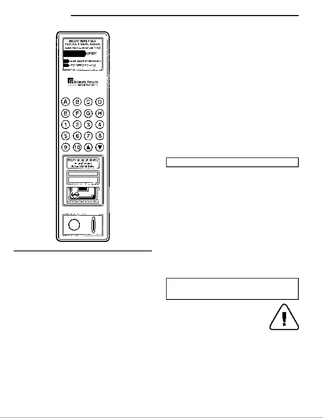
door - inside front
1 16000014 Door Only, Euro Style, Specify Color
16000018 Door Only, Standard, Specify Color
2 420303 Control Board Stand - Off
3 360206 Control Board w/MDB
(Requires Cover 202325)
4 680547 Harness Changer Plug-In
680567 Harness Changer Plug-In, Executive Export
680576 Harness MDB
5 202325 Control Board Cover Only
660528 Control Board Cover w/Decal
460628 Decal Only
460671 Decal, Dutch
6 201-6R7
Screw, Round Head, Phillips, Type B (6-18 x 7/16), Qty. 2
7 420062-1 Screw Round Hd.Slot Mach (4-36 x 3/4)
8 460436 Insulation, Rubber, 143’’ (Order length needed)
9 380022-5 Lamp, Fluorescent (F18T8 CW-24)
10 750141 Window, Front (44-5/8 x 26-7/8 x 1/8)
NOTE: Replacement Glass Must Be Hard
Tempered or Lexan Only.
460570 Decal, “Cool-Cool” (not shown)
11 201-6R11
Screw, Round Head, Phillips, Type B (6-20 x 11/16)
12 201381 -3 Shield & Window Clamp
13 201384 Window Clamp, Bottom
14 114-41-8 Screw, Hex Head, Machine (1/4-20 x 1/2)
15 420010 Washer
16 300156 Nut, Special, Door Stop Anchor
17 400192 Door Stop
18 200906 Delivery Bin Anchor Strap
19 217-8R10 Screw, Pan Head, Phillips, Type A (8 x 5/8)
20 210-8R6 Screw, (8-32 x 3/8)
21 Assembly Complete, Delivery Bin (See page
31 for itemized parts)
22 600179-1 Cash Box
12000088 Cash Box Stop (Not Shown)
23 600714 Cash Box Mounting Bracket
24 400180 Cash Box Retainer
25 420003-1 Screw, Flat Head (1/4-20 x 1/2)
26 420003 Screw, Flat Head (1/4-20 x 3/4)
27 420040-9 Hole Plug
28 640154 Lower Hinge Plate
29 420010-18 Washer
31 202024 Changer Socket Bracket
202775 Loading Barricade Closer (Not Shown)
32 305-7R8 Screw, Pan Hd.Plastite Phillips (#7 x 1/2)
33 400112 Spring Locking Bar
34 600432-3 Locking Bar Only
35 201660 Coin Return Bracket
36 440289 Coin Return Button, Gray
440289-3 Coin Return Button, Black
37 660370 Assembly, Validator Filler, Black
660370-3 Assembly, Validator Filler, Gray
38 420144 Ferrule
39 660519 Assembly, Selector Switch Panel
40 440304 Selector Buttons, Quantity - 20
41 440390 Instruction Glass
440401 Instruction Glass, French
440400 Instruction Glass, Mexico
440402 Instruction Glass, Dutch
440403 Instruction Glass, German
440440 Instruction Glass, Italian
17400005 Instruction Glass, Russian
17400007 Instruction Glass, Hungary
42 660517 Assembly Complete, Selector Bezel, Gray
660517-1 Assembly Complete, Selector Bezel, Black
440389-1 Selector Bezel Only, Gray
440389 Selector Bezel Only, Black
43 404-8 Nut, Hex Head (8-32)
44 118-10-8 Bolt, Carriage (10-24 x 1/2)
45 660319 Assembly Complete, Lock Handle w/Lock
Arm & Nut
46 201712 Coin Chute Bracket
47 440311 Coin Chute, Plastic
48 660488 Assembly, Coin Chute, Plastic
49 660367 Assembly Complete, Coin Return
640152 Assembly, Coin Return Bracket
50 400007 Spring
51 201703 Coin Return Link
52 751-25 Retaining Ring (1/4)
53 660581 Coin Cup Front Assembly, Black
660581-1 Coin Cup Front Assembly, Gray
440411 Trim, Coin Cup, Black
440411-1 Trim, Coin Cup, Gray
440412 Coin Cup Door (not shown)
54 400108 Spring (Not Shown)
440413 Coin Return Cup, LCM All - No Striker
660570 Assembly Coin Cup w/Striker Export
202432 Striker Door Switch Export
300184 Shoulder Bushing (2) Export
276-8R6 Screw Pan Hd Self Tap (8-32x3/8)(2)
400188 Spring Striker Door Switch Export
55 460041 Insulation, Foam (Order length needed)
56 12000010 Window, Side Shield, Lock Side
57 640131 Lock Arm Only
58 404-10 Nut, Hex Head (10-24)
59 680548 Harness, Bill Validator Hook-Up
680641 Harness Mars MDB 24 Volt
680613 Harness, MDB/Fan Cross Flow
60 440414 Coin Cup Chute
61 680512 Harness, Lamp
680456-1 Harness, Lamp (not shown)
62 380023 Starter, FS-25
380023-4 Starter, FS-11, 240V
63 750097 Lock and Cam for Cash Box. w/2 keys.
Specify Number.
420020 Lock w/1 key. Specify Number.
13100005-01
Cam Cash Box Locking only.
64 460629 Decal Mode Instructions, English
460672 Decal Mode Instructions, Dutch
460679 Decal Mode Instructions, Italian
460680 Decal Mode Instructions, Spain
460685 Decal Mode Instructions, German
460645 Decal Mode Instructions, French
65 300206 Window Screw (Not Shown)
16