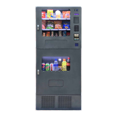
Wurlitzer International L User manual

R
International L
Operating Instructions
GB
16
14
10 11 12 13 16 17
15 18 19 20 21
22 23 24 25 26 27 28 29 30 31 32 33
34 35 36 37 38 39 40 41 42 43 44 45
R
1,- / 2,-
5,- DM
INTERNATIONAL L
INTERNATIONAL L
7


INTERNATIONAL L – Edition: 17.02.2006 1
1 Description of the Vending Machine. . . . . . . . . . . . . . . . . . . . . . . . . . . . . . . . . . . 7
1.1 General Description. . . . . . . . . . . . . . . . . . . . . . . . . . . . . . . . . . . . . . . . . . . . . . . . . . . . . . . . . . . . . . . . 7
1.1.1 Standard Equipment . . . . . . . . . . . . . . . . . . . . . . . . . . . . . . . . . . . . . . . . . . . . . . . . . . . . . . . . . . . . . . . . 7
1.1.2 Optional Equipment. . . . . . . . . . . . . . . . . . . . . . . . . . . . . . . . . . . . . . . . . . . . . . . . . . . . . . . . . . . . . . . . . 7
1.2 Dimensions, Weight and Capacity. . . . . . . . . . . . . . . . . . . . . . . . . . . . . . . . . . . . . . . . . . . . . . . . . . . . 8
2 Unpacking, Transport and Installation . . . . . . . . . . . . . . . . . . . . . . . . . . . . . . . . . 9
2.1 Unpacking and Transport . . . . . . . . . . . . . . . . . . . . . . . . . . . . . . . . . . . . . . . . . . . . . . . . . . . . . . . . . . . 9
2.2 Package Contents . . . . . . . . . . . . . . . . . . . . . . . . . . . . . . . . . . . . . . . . . . . . . . . . . . . . . . . . . . . . . . . . . 9
2.3 Installation of the Vending Machine . . . . . . . . . . . . . . . . . . . . . . . . . . . . . . . . . . . . . . . . . . . . . . . . . 10
2.4 Inserting Brand Labels . . . . . . . . . . . . . . . . . . . . . . . . . . . . . . . . . . . . . . . . . . . . . . . . . . . . . . . . . . . . 10
2.5 Exchange of the Picture Display . . . . . . . . . . . . . . . . . . . . . . . . . . . . . . . . . . . . . . . . . . . . . . . . . . . . 11
3 Conversion of the Product Columns . . . . . . . . . . . . . . . . . . . . . . . . . . . . . . . . . 12
3.1 Adjusting Product Columns . . . . . . . . . . . . . . . . . . . . . . . . . . . . . . . . . . . . . . . . . . . . . . . . . . . . . . . . 13
3.1.1 Adjusting the Width of a Product Column . . . . . . . . . . . . . . . . . . . . . . . . . . . . . . . . . . . . . . . . . . . . . . . 13
3.1.2 Adjusting the Depth of a Short Product Column – Length of Packs 75 mm/2.9 inches to 105
mm/4.1 inches . . . . . . . . . . . . . . . . . . . . . . . . . . . . . . . . . . . . . . . . . . . . . . . . . . . . . . . . . . . . . . . . . . . . 14
3.1.3 Adjusting the Clearance Height of a Product Column . . . . . . . . . . . . . . . . . . . . . . . . . . . . . . . . . . . . . . 15
3.2 Conversion Long Column/Short Column . . . . . . . . . . . . . . . . . . . . . . . . . . . . . . . . . . . . . . . . . . . . . 17
4 Taking the Vending Machine into Operation . . . . . . . . . . . . . . . . . . . . . . . . . . . 18
4.1 Connection and First Steps . . . . . . . . . . . . . . . . . . . . . . . . . . . . . . . . . . . . . . . . . . . . . . . . . . . . . . . . 18
5 Programming of the machine . . . . . . . . . . . . . . . . . . . . . . . . . . . . . . . . . . . . . . . 19
5.1 The programming terminal. . . . . . . . . . . . . . . . . . . . . . . . . . . . . . . . . . . . . . . . . . . . . . . . . . . . . . . . . 19
5.2 The state ’IN OPERATION‘ . . . . . . . . . . . . . . . . . . . . . . . . . . . . . . . . . . . . . . . . . . . . . . . . . . . . . . . . . 19
5.3 The service programs (overview). . . . . . . . . . . . . . . . . . . . . . . . . . . . . . . . . . . . . . . . . . . . . . . . . . . . 20
5.4 How to leave the service program: . . . . . . . . . . . . . . . . . . . . . . . . . . . . . . . . . . . . . . . . . . . . . . . . . . 20
6 Programming of vend prices. . . . . . . . . . . . . . . . . . . . . . . . . . . . . . . . . . . . . . . . 21
6.1 Different selections with different prices . . . . . . . . . . . . . . . . . . . . . . . . . . . . . . . . . . . . . . . . . . . . . 21
6.2 Several selections with identical prices . . . . . . . . . . . . . . . . . . . . . . . . . . . . . . . . . . . . . . . . . . . . . . 21
7 Machine test - service program 07 . . . . . . . . . . . . . . . . . . . . . . . . . . . . . . . . . . . 23
8 Optional button/column allocation - service program 09 . . . . . . . . . . . . . . . . . 24
8.1 Following button/column allocations are possible . . . . . . . . . . . . . . . . . . . . . . . . . . . . . . . . . . . . . 24
8.1.1 One selection drives one column with different number . . . . . . . . . . . . . . . . . . . . . . . . . . . . . . . . . . . . 24
8.1.2 One selection drives different columns alternately . . . . . . . . . . . . . . . . . . . . . . . . . . . . . . . . . . . . . . . . 25
8.1.3 Several selections driving one column . . . . . . . . . . . . . . . . . . . . . . . . . . . . . . . . . . . . . . . . . . . . . . . . . 25
8.1.4 Several selections driving alternately same number of columns, i.e. columns deliver evenly no
matter which column was selected.. . . . . . . . . . . . . . . . . . . . . . . . . . . . . . . . . . . . . . . . . . . . . . . . . . . . 26
8.1.5 Reset of this button/column allocation shown in example 8.1.4 . . . . . . . . . . . . . . . . . . . . . . . . . . . . . . 27
8.1.6 Reset of a l l button/column allocations in service program 09 . . . . . . . . . . . . . . . . . . . . . . . . . . . . . . 28

INTERNATIONAL L – Edition:17.02.2006
2
9 Operation with MDB . . . . . . . . . . . . . . . . . . . . . . . . . . . . . . . . . . . . . . . . . . . . . . . 29
9.1 Filling the tubes. . . . . . . . . . . . . . . . . . . . . . . . . . . . . . . . . . . . . . . . . . . . . . . . . . . . . . . . . . . . . . . . . . 29
9.2 Display shows: "PLEASE INSERT EXACT MONEY" . . . . . . . . . . . . . . . . . . . . . . . . . . . . . . . . . . . . 29
9.3 How to empty the tubes - service program 07 . . . . . . . . . . . . . . . . . . . . . . . . . . . . . . . . . . . . . . . . . 29
9.3.1 Emptying all the tube. . . . . . . . . . . . . . . . . . . . . . . . . . . . . . . . . . . . . . . . . . . . . . . . . . . . . . . . . . . . . . . 29
9.3.2 Emptying single tubes - service program 07. . . . . . . . . . . . . . . . . . . . . . . . . . . . . . . . . . . . . . . . . . . . . 30
9.4 Programming max. change - service program 08 . . . . . . . . . . . . . . . . . . . . . . . . . . . . . . . . . . . . . . 30
9.5 Vend mode - service program 10, button R . . . . . . . . . . . . . . . . . . . . . . . . . . . . . . . . . . . . . . . . . . . 31
9.6 Coin acceptance options - Cancellation of individual coins - service program 12 . . . . . . . . . . . 32
9.7 Test credit - service program 11 . . . . . . . . . . . . . . . . . . . . . . . . . . . . . . . . . . . . . . . . . . . . . . . . . . . . 33
9.8 Number of coins to be accepted - service program 14 . . . . . . . . . . . . . . . . . . . . . . . . . . . . . . . . . . 33
9.9 "Data block" transfer - service program 11, button 1 . . . . . . . . . . . . . . . . . . . . . . . . . . . . . . . . . . . 34
9.10 Programming of the bill input - service programs 11, 12, 14 . . . . . . . . . . . . . . . . . . . . . . . . . . . . . 34
9.10.1 Programming of the bill value - service program 11, button 9. . . . . . . . . . . . . . . . . . . . . . . . . . . . . . . . 34
9.10.2 Programming of bill options - service program 12, button 9 . . . . . . . . . . . . . . . . . . . . . . . . . . . . . . . . . 35
9.10.3 Programming number of bills to be accepted before a vend - service program 14, button 6 . . . . . . . . 35
10 MDB coin system - statistics . . . . . . . . . . . . . . . . . . . . . . . . . . . . . . . . . . . . . . . . 36
10.1 Sales per selection - service program 01 (resetable) . . . . . . . . . . . . . . . . . . . . . . . . . . . . . . . . . . . 36
10.2 Total sales of all selections - service program 03 (resetable). . . . . . . . . . . . . . . . . . . . . . . . . . . . . 36
10.3 How to call up statistical data - service program 05 - 06. . . . . . . . . . . . . . . . . . . . . . . . . . . . . . . . . 36
10.4 Individual counter reset . . . . . . . . . . . . . . . . . . . . . . . . . . . . . . . . . . . . . . . . . . . . . . . . . . . . . . . . . . . 37
10.5 Reset of all counters - service program 04, button 8. . . . . . . . . . . . . . . . . . . . . . . . . . . . . . . . . . . . 38
11 Operation with coin systems according to Executive standard. . . . . . . . . . . . 38
12 Operation with coin systems according to BDV standard . . . . . . . . . . . . . . . . 39
12.1 Filling the change tubes . . . . . . . . . . . . . . . . . . . . . . . . . . . . . . . . . . . . . . . . . . . . . . . . . . . . . . . . . . . 39
12.2 Display "PLEASE INSERT EXACT MONEY". . . . . . . . . . . . . . . . . . . . . . . . . . . . . . . . . . . . . . . . . . . 39
12.3 Manual coin dispense - service program 07. . . . . . . . . . . . . . . . . . . . . . . . . . . . . . . . . . . . . . . . . . . 39
12.4 Dispense of single tubes - service program 07 . . . . . . . . . . . . . . . . . . . . . . . . . . . . . . . . . . . . . . . . 40
12.5 Programming maximum change - service program 08, button R. . . . . . . . . . . . . . . . . . . . . . . . . . 40
12.6 Programming maximum coin insertion - service program 11, button 1 . . . . . . . . . . . . . . . . . . . . 40
12.7 BDV vend mode - service program 11, button 7. . . . . . . . . . . . . . . . . . . . . . . . . . . . . . . . . . . . . . . . 41
12.8 Test vend . . . . . . . . . . . . . . . . . . . . . . . . . . . . . . . . . . . . . . . . . . . . . . . . . . . . . . . . . . . . . . . . . . . . . . . 41
12.9 Disabling single coins - service program 11, button 5 . . . . . . . . . . . . . . . . . . . . . . . . . . . . . . . . . . 42
12.10 Programming those coins to be disabled immediately after the display shows "PLEASE
INSERT EXACT MONEY" . . . . . . . . . . . . . . . . . . . . . . . . . . . . . . . . . . . . . . . . . . . . . . . . . . . . . . . . . . 43
12.11 Modifying responses to "tube empty" messages - service program 11, button 2 . . . . . . . . . . . . 44
13 Vend statistics with coin systems acc. to BDV standard . . . . . . . . . . . . . . . . . 45
13.1 Sales per compartment (selection) - service program 01 (resetable) . . . . . . . . . . . . . . . . . . . . . . 45
13.2 Total sales of all compartments - service program 03 (resetable) . . . . . . . . . . . . . . . . . . . . . . . . . 45
13.3 Statistical data (BDV standard) - service programs 05 - 06. . . . . . . . . . . . . . . . . . . . . . . . . . . . . . . 45
13.4 Individual resetting of counters. . . . . . . . . . . . . . . . . . . . . . . . . . . . . . . . . . . . . . . . . . . . . . . . . . . . . 46
13.5 Overall resetting of counters - service program 04, button 8. . . . . . . . . . . . . . . . . . . . . . . . . . . . . 47
INTERNATIONAL L – Edition: 17.02.2006 3
14 Operating information . . . . . . . . . . . . . . . . . . . . . . . . . . . . . . . . . . . . . . . . . . . . . 48
14.1 Counter, current supply interruptions - service program 04 (resetable) . . . . . . . . . . . . . . . . . . . . 48
14.2 Entering customer number or machine number - service program 05 . . . . . . . . . . . . . . . . . . . . . 48
14.3 Security number in four digits - service program 05 . . . . . . . . . . . . . . . . . . . . . . . . . . . . . . . . . . . . 48
14.4 Operating time - service program 15 (NOT resetable) . . . . . . . . . . . . . . . . . . . . . . . . . . . . . . . . . . . 48
15 The LCD display . . . . . . . . . . . . . . . . . . . . . . . . . . . . . . . . . . . . . . . . . . . . . . . . . . 49
15.1 Technical data . . . . . . . . . . . . . . . . . . . . . . . . . . . . . . . . . . . . . . . . . . . . . . . . . . . . . . . . . . . . . . . . . . . 49
15.2 Programming . . . . . . . . . . . . . . . . . . . . . . . . . . . . . . . . . . . . . . . . . . . . . . . . . . . . . . . . . . . . . . . . . . . . 49
15.3 Messages . . . . . . . . . . . . . . . . . . . . . . . . . . . . . . . . . . . . . . . . . . . . . . . . . . . . . . . . . . . . . . . . . . . . . . . 51
15.4 Message display in the editor. . . . . . . . . . . . . . . . . . . . . . . . . . . . . . . . . . . . . . . . . . . . . . . . . . . . . . . 52
15.5 Meaning of the place holders. . . . . . . . . . . . . . . . . . . . . . . . . . . . . . . . . . . . . . . . . . . . . . . . . . . . . . . 52
15.6 Description of the used place holders. . . . . . . . . . . . . . . . . . . . . . . . . . . . . . . . . . . . . . . . . . . . . . . . 53
15.7 What the messages tell you . . . . . . . . . . . . . . . . . . . . . . . . . . . . . . . . . . . . . . . . . . . . . . . . . . . . . . . . 54
15.8 Suggestions to programme . . . . . . . . . . . . . . . . . . . . . . . . . . . . . . . . . . . . . . . . . . . . . . . . . . . . . . . . 55
15.9 Programming example . . . . . . . . . . . . . . . . . . . . . . . . . . . . . . . . . . . . . . . . . . . . . . . . . . . . . . . . . . . . 57
15.10 How to format text memory - service program 15 . . . . . . . . . . . . . . . . . . . . . . . . . . . . . . . . . . . . . . 58
15.11 How to programme the text memory applying PC . . . . . . . . . . . . . . . . . . . . . . . . . . . . . . . . . . . . . . 59
16 Statistic print outs . . . . . . . . . . . . . . . . . . . . . . . . . . . . . . . . . . . . . . . . . . . . . . . . 60
16.1 How to connect the printer . . . . . . . . . . . . . . . . . . . . . . . . . . . . . . . . . . . . . . . . . . . . . . . . . . . . . . . . . 60
16.2 Print-out of statistics. . . . . . . . . . . . . . . . . . . . . . . . . . . . . . . . . . . . . . . . . . . . . . . . . . . . . . . . . . . . . . 61
16.3 Print-out of set commodity prices . . . . . . . . . . . . . . . . . . . . . . . . . . . . . . . . . . . . . . . . . . . . . . . . . . . 61
17 Statistic print out MDB. . . . . . . . . . . . . . . . . . . . . . . . . . . . . . . . . . . . . . . . . . . . . 62
18 Statistic print out NRI Simplex 5 or Executive. . . . . . . . . . . . . . . . . . . . . . . . . . 64
19 Statistic print out BDV standard . . . . . . . . . . . . . . . . . . . . . . . . . . . . . . . . . . . . . 65
20 Initialisation of an IVC unit after replacement . . . . . . . . . . . . . . . . . . . . . . . . . . 67
20.1 Preparation for initialisation. . . . . . . . . . . . . . . . . . . . . . . . . . . . . . . . . . . . . . . . . . . . . . . . . . . . . . . . 67
20.2 Programming of configuration numbers. . . . . . . . . . . . . . . . . . . . . . . . . . . . . . . . . . . . . . . . . . . . . . 67
20.3 For machines with MDB - carry out ’data block transfer’ Service program 11, button 1 . . . . . . . 69
20.4 Control of coin acceptance and change adjustment . . . . . . . . . . . . . . . . . . . . . . . . . . . . . . . . . . . . 69
20.4.1 Machines with MDB system. . . . . . . . . . . . . . . . . . . . . . . . . . . . . . . . . . . . . . . . . . . . . . . . . . . . . . . . . . 69
20.4.2 Machines with coin system acording to BDV standard . . . . . . . . . . . . . . . . . . . . . . . . . . . . . . . . . . . . . 70
20.5 Machine specification self-test. . . . . . . . . . . . . . . . . . . . . . . . . . . . . . . . . . . . . . . . . . . . . . . . . . . . . . 71
21 Service programs (in tabular form). . . . . . . . . . . . . . . . . . . . . . . . . . . . . . . . . . . 72
21.1 MDB and Executive coin systems . . . . . . . . . . . . . . . . . . . . . . . . . . . . . . . . . . . . . . . . . . . . . . . . . . . 72
21.2 Coin systems according to BDV standard . . . . . . . . . . . . . . . . . . . . . . . . . . . . . . . . . . . . . . . . . . . . 75
22 Overview EPROM letter codes. . . . . . . . . . . . . . . . . . . . . . . . . . . . . . . . . . . . . . . 77

INTERNATIONAL L – Edition:17.02.2006
4
23 Error messages . . . . . . . . . . . . . . . . . . . . . . . . . . . . . . . . . . . . . . . . . . . . . . . . . . . 78
23.1 IVC unit. . . . . . . . . . . . . . . . . . . . . . . . . . . . . . . . . . . . . . . . . . . . . . . . . . . . . . . . . . . . . . . . . . . . . . . . . 78
23.2 LED yellow on the IVC unit. . . . . . . . . . . . . . . . . . . . . . . . . . . . . . . . . . . . . . . . . . . . . . . . . . . . . . . . . 78
23.2.1 CONTINUOUS yellow light:. . . . . . . . . . . . . . . . . . . . . . . . . . . . . . . . . . . . . . . . . . . . . . . . . . . . . . . . . . 78
23.2.2 BLINKING yellow light: . . . . . . . . . . . . . . . . . . . . . . . . . . . . . . . . . . . . . . . . . . . . . . . . . . . . . . . . . . . . . 78
23.3 Extension cable. . . . . . . . . . . . . . . . . . . . . . . . . . . . . . . . . . . . . . . . . . . . . . . . . . . . . . . . . . . . . . . . . . 78
23.4 The state ’OUT OF ORDER’ . . . . . . . . . . . . . . . . . . . . . . . . . . . . . . . . . . . . . . . . . . . . . . . . . . . . . . . . 79
23.5 The LCD display does not show anything . . . . . . . . . . . . . . . . . . . . . . . . . . . . . . . . . . . . . . . . . . . . 79
23.6 List of error . . . . . . . . . . . . . . . . . . . . . . . . . . . . . . . . . . . . . . . . . . . . . . . . . . . . . . . . . . . . . . . . . . . . . 80
24 Technical Data . . . . . . . . . . . . . . . . . . . . . . . . . . . . . . . . . . . . . . . . . . . . . . . . . . . . 84
24.1 Type Plate/Signboards . . . . . . . . . . . . . . . . . . . . . . . . . . . . . . . . . . . . . . . . . . . . . . . . . . . . . . . . . . . . 84
24.2 Technical / Electrical Data . . . . . . . . . . . . . . . . . . . . . . . . . . . . . . . . . . . . . . . . . . . . . . . . . . . . . . . . . 84
24.3 Fuse on the IVC2 Control Unit . . . . . . . . . . . . . . . . . . . . . . . . . . . . . . . . . . . . . . . . . . . . . . . . . . . . . . 84
25 Technical Appendix. . . . . . . . . . . . . . . . . . . . . . . . . . . . . . . . . . . . . . . . . . . . . . . . 85
25.1 Filling Plan International L . . . . . . . . . . . . . . . . . . . . . . . . . . . . . . . . . . . . . . . . . . . . . . . . . . . . . . . . . 85
25.2 Connecting Diagram. . . . . . . . . . . . . . . . . . . . . . . . . . . . . . . . . . . . . . . . . . . . . . . . . . . . . . . . . . . . . . 86
26 Declarations of Conformity . . . . . . . . . . . . . . . . . . . . . . . . . . . . . . . . . . . . . . . . . 87

General Description
International L – edition: 17.02.2006 7
1 Description of the Vending Machine
1.1 General Description
The vending machineis a dispenser for hard and soft packs.
*) standard packs of 20 cigarettes
The width and length of the product columns and the clearance height can be adjusted according to
the size of the packs. All columns are equipped with single drive units and with sensors for indicating
that the columns are empty.
1.1.1 Standard Equipment
!Programmable microprocessor controller with data capture
!Alphanumeric display in two lines
!Closing mechanism with multiple locking
!Steel cabinet for increased protection against burglary
!Showcase with illuminated advertising, picture can be exchanged
!Strong metal keyboard with integrated return button for motor-driven change return
!Illuminated brands and price labels
!Display indicating that the columns are empty
!Infrared sensor for reading statistical data by means of a mobile data capture device. You can
purchase this device separately at specialized distributors – the infrared sensor is the interface
which is necessary for reading the data.
1.1.2 Optional Equipment
NOTE: If you are interested in optional equipment, please contact your distributor of
Deutsche Wurlitzer GmbH machines.
Accessories and Assemblies for Conversion
!Printer for statistical data
!Safe cash box
!Tobacco columns
!Long dividers to convert short columns to long columns
International L 35/27 35/35
selections 27 35
long columns 30 packs each 18 18
long columns 24 packs each 9 1
short columns 10 packs each - 16
columns for 100 mm cigarettes 2 2
total capacity of packs *) 756 724

Dimensions, Weight and Capacity
International L – edition: 17.02.2006
8
Payment Systems
!ECA (Electronic Coin Acceptor)
!Coin systems
!Credit card systems
payment by means of a charged chip on the credit card
!Change giver over a separate 5 tubes change giver
!Bill acceptor
!Change return with hopper
1.2 Dimensions, Weight and Capacity
International L
weight (net) 140 kg/308.6 lbs
selections 27 to 35
max. capacity 756
! " # $ % & '
! " # $ % & ' ! ! ! ! !
! " ! # ! $ ! % ! & ! ' " " " " ! " " " #
705 mm/27.5 in 617 mm/24.1 in (L)
140 mm
430 mm/16.8 in (L)
600 mm/23.4 in (L)
1293 mm/50.4 in
530 mm/20.7 in
1365 mm/53.2 in
1287 mm/50.2 in
355 mm/13.9 in
475 mm/18.5 in
625 mm/24.4 in
5.5 in

Unpacking and Transport
International L – edition: 17.02.2006 9
2Unpacking, Transport and Installation
2.1 Unpacking and Transport
The vending machine is delivered on a pallet, boxed.
1. Remove packaging.
2. Take the vending machine off the pallet.
WARNING! Danger of injury!
The vending machine has a weight of 140 kg/308.6 lbs. Do not transport the vending machine on
your own. Use appropriate equipment or call on a second person’s help.
On the rear side of the vending machine you can find two handles for carrying the vending machine.
To do so, four persons are needed.
The transport with a sack trolley is easier and more comfortable.
NOTE: Wheels are installed at the bottom of the vending machine. For short distances, the
vending machine can be transported by means of these wheels on even surfaces without
obstacles.
2.2 Package Contents
The package contents includes:
!Keys for the vending machine
The keys are placed on the front of the vending machine in the product delivery bin.
!Operating instructions
Place the operating instructions in the lower part of the vending machine. Thus, it is available to
all users.
!Square for reducing the clearance height
The square (1 x) is placed in a bag in the cash box of the vending machine. It is needed to adjust
the clearance height according to the size of the packs.
!Fuses
An extra fuse (T3.15amps) is placed in the bag in the cash box.
!Adjusting divider for converting a column
The adjusting divider for a short column (1x) is placed in a bag in the cash box of the vending
machine.

Installation of the Vending Machine
International L – edition: 17.02.2006
10
2.3 Installation of the Vending Machine
The correct installation of the vending machine is a decisive factor for the correct functioning. The
vending machine can only be operated safely for a long time if the place of installation is dry.
WARNING! Danger to life from electric shock!
Be sure that a socket with a ground conductor is available.
In order to install the vending machine correctly, follow the steps below:
1. Install the vending machine at a place which is
freely accessible. Thus, the vending machine can
easily be filled and cleaned.
2. Align the vending machine with the aid of a spirit
level. The vending machine must be in a vertical
position in order to guarantee that the coin
acceptor functions correctly and that the door of
the vending machine can be opened without any
problems. Use the square plastic screws to
adjust and to fix the vending machine. Be sure
that the vending machine is placed on an even
surface.
3. Take the bag with the accessories out of the cash box of the vending machine.
4. Pass the power cable through the round hole on the rear side of the vending machine; then,
close the hole by means of the cover. The cover is primarily used to relieve the power cable
from tension.
"The vending machine is now installed correctly. Let’s now take the vending machine into
operation, see page 18.
2.4 Inserting Brand Labels
The brand labels for the selling products are not included in the package contents.
In order to insert brand labels, follow the steps below:
1. Open the door of the vending machine.
2. Open the inner door by pulling the red
handle.
3. Insert the brand labels into the transparent
films corresponding to the different
products.
4. Close the inner door and the door of the
vending machine.
"The insertion of brand and price labels is
completed.

Exchange of the Picture Display
International L – edition: 17.02.2006 11
2.5 Exchange of the Picture Display
The vending machine is delivered with a standard picture. It is easy to replace it by another.
NOTE: You would like to change the picture?
Deutsche Wurlitzer GmbH or your distributor offers a selection of pictures.
In order to exchange the picture, follow the steps below:
1. Open the door of the vending machine.
2. Open the inner door by pulling the red handle.
3. Unscrew the thumb screw and turn the glass clamp.
4. Remove the acrylic glass pane by pulling it upwards.
5. Take the acrylic glass pane as model for cutting the new picture.
6. Exchange the picture.
7. Replace the acrylic glass pane and install it.
8. Close the inner door and the door of the vending machine.
"The exchange of the picture is completed.

Exchange of the Picture Display
International L – edition: 17.02.2006
12
3 Conversion of the Product Columns
The product columns 22 to 37 (see figure below) can be converted to long or short columns. To do
so, special dividers are necessary – contact Deutsche Wurlitzer GmbH or your distributor if
necessary.
Ensure the correct functioning of the vending machine!
If you change the number of product columns between the columns 22 to 37, you have to adjust the
assignment of product selection and motor again.
selections: maximum 35
capacity: maximum 510 packs
middle column: 9 x 63 mm/2.5 in
(max. 597 mm/23.3 in)
rear column: 11 x 63 mm/2.5 in
(max. 693 mm/27.0 in)
doorcolumn7x63mm/2.5in
(max. 451mm/17.6in)
standard: 6 long columns, 6 short columns
225 mm/8.8 in225 mm/8.8 in
685 mm/26.7 in (30 packs)
560 mm/21.8 in (24 packs)
685 mm/26.7 in (30 packs)
The middle columns have a depth of 110 mm/4.3 inches.
The rear columns and the columns in the door have a depth of 93 mm/3.6 inches.
(10 packs) (10 packs)

Adjusting Product Columns
International L – edition: 17.02.2006 13
3.1 Adjusting Product Columns
3.1.1 Adjusting the Width of a Product Column
After delivery, all the product columns are adjusted to a width of 63 mm/2.5 inches. This adjustment
corresponds to the width of standard packs and in general does not need to be adjusted.
The width of the product columns can be extended by moving the dividers to the side in intervals of 3
mm/0.12 inches. For a safe functioning of the vending machine, the width of the product columns
should be "width of packs + 2 mm/0.08 inches".
NOTE: If you extend a product column, another column must be dropped as the minimum
width of 63 mm/2.5 inches cannot be maintained for all columns.
In order to adjust the width of the product columns, follow the steps below:
1. Open the door.
2. Determine the product column which should be extended and the product column which should
be dropped.
3. Take the corresponding divider at the top and the bottom and pull it upwards until the locking is
released.
4. Remove the motor of the product column which should be dropped. To do so, loosen the cable
connection at the motor, pull the locking lever at the motor and remove the motor.
5. Move the divider according to the width of the products and press the divider downwards until
the locking locks in place.
6. Adjust the assignment of product selection and motor according to the conversion.
7. Change the selling price if necessary, QQQ.
8. Check whether the settings of the product columns for the length and height of the products
correspond to the new format of the packs, adjust the settings if necessary.
!Adjusting the depth of a product column, see page 14.
!Adjusting the clearance height of a product column, see page 15.
9. Fill products into the product columns.
10. Perform some test vends. Adjust the settings for the product column if problems occur during
the test vends.
11. Update the corresponding brand and price labels, see page 10.
12. Update the filling plan of the vending machine, see page 85.
13. Close the door.
"The adjustment of the width of the product column is completed and the vending machine is
ready for operation again.

Adjusting Product Columns
International L – edition: 17.02.2006
14
3.1.2 Adjusting the Depth of a Short Product Column – Length of Packs 75 mm/2.9 inches to 105
mm/4.1 inches
International L: middle column
International M: rear column
Vision: columns 10 to 14 and 20 to 24
!The short columns in the rear of the International M have different heights.
!The "short" short columns have a height of 225 mm/8.7 inches.
!The "longer" short columns have a height of 355 mm/13.9 inches.
!The short columns of the Vision have different heights.
!The columns 10 to 14 have a height of 230 mm/9.0 inches.
!The columns 20 to 24 have a height of 430 mm/16.8 inches.
For long and standard packs you have to position the adjusting lever as shown in the picture below.
In case you want to vend short packs from the short columns you have to insert the adapter rail from
the accessories bag (see picture RH side).
Setting for:
!long packs: without adapter rail, install adjusting lever in rear position
!standard packs: without adapter rail, install adjusting lever in middle position
!short packs: install adapter rail, install adjusting lever in front position
long packs
90 mm/3.5 in to 105 mm/4.1 in 75 mm/2.9 in to 90 mm/3.5 in short packs
up to75 mm/2.9 in
standard packs
adjusting lever
rear position adjusting lever
middle position adjusting lever
front position adapter rail
installed

Adjusting Product Columns
International L – edition: 17.02.2006 15
3.1.3 Adjusting the Clearance Height of a Product Column
The clearance height of the product columns has to be adjusted according to the height of packs.
The vending machine is set to a clearance height of 18 mm/0.7 inches to 26 mm/1.0 inches by
default.
Optimum clearance height = height of packs + 2 mm/
0.08 inches.
Two possibilities exist to adjust the clearance height:
!Adjusting the clearance height by displacing the motor, see page 16.
!Adjusting the clearance height by moving the square, see page 16.
By combining the two possibilities, it is possible to adjust the clearance height for all common width
of packs. The following pages will help you with this task.
Width of packs[mm] Position of the motor Square for reducing the clearance height
10 mm/0.4 in to
18 mm/0.7 in motor installed in upper position square for reducing the clearance height
18 mm/0.7 in to
26 mm/1.0 in motor installed in upper position without square for reducing the clearance
height
26 mm/1.0 in to
32 mm/1.3 in motor installed in lower position square for reducing the clearance height
32 mm/1.3 in to
40 mm/1.6 in motor installed in lower position without square for reducing the clearance
height
height of packs+ min. 2 mm/0.08 in

Adjusting Product Columns
International L – edition: 17.02.2006
16
Adjusting the Clearance Height by Displacing the Motor
Install the motor in the upper or lower position.
!Pull the red locking lever and remove the motor.
The motor can be installed in the upper or lower posi-
tion again.
!Upper position (lower slot):
clearance height 18 mm/0.7 inches to 26 mm/1.0
inches
!Lower position (upper slot):
clearance height 32 mm/1.3 inches to 40 mm/1.6
inches
Adjusting the Clearance Height by Moving the Square Positions
The squares for reducing the clearance reduce the clearance of the corresponding product column
by 8 mm/0.3 inches – if they are screwed to the adjusting levers.
The accessories contain the square for reducing the
clearance (1 x).
locking lever
upper slotlower slot

Conversion Long Column/Short Column
International L – edition: 17.02.2006 17
3.2 Conversion Long Column/Short Column
If you want to extend your product selections, you can convert the long columns of the vending
machine into two short columns respectively. To do so, special dividers and additional motors are
needed.
NOTE: Deutsche Wurlitzer GmbH or your distributor offer dividers for short columns and
motors.
Part numbers:
long column (0047402)
short column (0048839)
Different from the standard settings after delivery, the long columns 21 to 31 can be converted into
short columns and the short columns 32 to 37 can be converted into long columns, see page 17.
Follow the steps below in order to convert short columns into long columns and vice versa:
NOTE: Detailed information about installing and removing the dividers, motors etc. can be
found in chapter "Adjusting Product Columns", see page 13.
!Remove the dividers of the product columns which should be converted.
!Remove the motors of the upper short columns if they are to be converted into long columns.
!Install the new dividers.
!Install the motors of the upper short columns if they were long columns before conversion.
!Adjust the new product columns according to the format of the packs (see page 13) and update
the assignment of product selection and motor.

Connection and First Steps
International L – edition: 17.02.2006
18
4Taking the Vending Machine into Operation
4.1 Connection and First Steps
The vending machine is pre-configured (basic configuration) so that it can easily be taken into
operation.
In order to take the vending machine into operation with its basic configuration, follow the steps
below:
1. Connect the vending machine to the socket.
#Message shown in the display:
2. Determine the filling of the product columns and write the
assignment of product/product column down in the filling plan, see page 85.
3. Be sure that the pack size of the selling products corresponds to the adjustments of the product
columns. If necessary, adjust the product columns again.
#Adjusting the width of a product column, see page 13.
#Adjusting the depth of a product column, see page 14.
#Adjusting the heigth for passage of a product column, see page 15.
4. Fill the products into the product columns (min. two packs per column).
5. IMPORTANT! Perform a motor test, see page 36.
6. Programme the vend prices, see page 29.
7. Perform some test vends with money when the door is open.
8. Close the machine door.
"The machine is now ready to work.
IN OPERATION

Programming of the machine
International L – edition: 17.02.2006 19
5 Programming of the machine
5.1 The programming terminal
The machine can be programmed by means of the selec-
tion buttons. Call up the service programs using the termi-
nal with four programming buttons inside the machine.The
four buttons of this panel control the following functions:
(S) SERVICE
Gives you access to the various service levels.
(D) DIGIT
Use to select single display digits during activated service
program.
(+) PLUS
Use to set the selected digit with values between 0 and 9.
(P) PROGRAMM
Use to save new inputs into memory.
5.2 The state ’IN OPERATION‘
Starting point is the status "IN OPERATION" indicated in the
display by message 0 (or message 9 in case the change
tubes are not yet filled, (see chapt. 15.7 on page 54).
If the text memory is empty, message 0 will appear,
programming is still possible.
You can call up 17 service programs with the programming
terminal.
Example service program call:
!Press button S once. Service program 01 is reached.
(see arrow)
!Text: “01_VENDS
___PER_SELECTION” is preset from factory
(message 31).
!If text memory is empty, the display shows:
“__.01”
(_ = space sign in reality).
NOTE: You can freely programme the LCD display. Therefore the following explanations only refer to
the service program numbers and data, which are displayed either through preset by factory or
through empty text memory.
MACHINE ACCEPTS
0.05 - 2.00 EURO
IN OPERATION
alterning with
00.00
Message 0 factory preset
01 VENDS PER
SELECTION
text memory preset from factory
.01
empty text memory

Programming of the machine
International L – edition: 17.02.2006
20
5.3 The service programs (overview)
ATTENTION!
Programs 11 to 17 should only be called up by those who have expert knowledge of the programs in-
volved or who have been properly trained to apply them. After any change in configuration, the ma-
chine does not revert to the previous mode of operation.
5.4 How to leave the service program:
Press key S until the display starts counting backwards (end of service program). The display will
show alternately "IN OPERATION" and "MACHINE ACCEPTS 0.05 - 2.00 EURO" or, in case the
change giver tubes are empty, "PLEASE INSERT EXACT MONEY" and "MACHINE ACCEPTS
0.05 - 0.50 EURO".
Second possibility:
Wait for some 60 seconds after that the machine automatically reverts to standard vending mode.
Section 1 Service programs 1 - 10
display of: statistics
sales
machine tests
programming of: vend prices
vend modes
selection options
To call up: Press key S until the desired program is found.
If you wish to return to any previous service program, keep key P pressed and press key S, service programs
will run back wards.
Section 2 Service programs 11 - 17
programming of: data transfer (only for NRI Simplex 0 or MDB)
coin options
change giver programming
maschine configuration
To call up:
!Press key S until display shows 7.
!Hold key P while pressing selection button 8 to display service program 11.
!Press S to call up service programs 12 to 17.
OR:
!You can take the steps in reverse order, too. Call up service program 17 by keeping key P down and by si-
multaneously pushing key S until you have the service program displayed.
Table of contents
Popular Vending Machine manuals by other brands

Necta
Necta Zenith Fresh Brew Instant Installation, operating and maintenance manual

Seaga
Seaga Space Saver Series Operator's manual

Seaga
Seaga Victory Series Operator's manual

Westomatic
Westomatic H2O Hydration Station Cleaning guide

Dixie Narco
Dixie Narco DNCB 168 Parts Service Troubleshooting Manual

Bradley
Bradley 401 troubleshooting guide