dlb AIJGO-61 User manual

1
www.dlb.hu +36 27 502 555sales@destsa.hu
INSTRUCTION
MANUAL
AIJGO-61
RESISTANCE METER

TABLE OF CONTENTS
Overview ...................................................3
The product and accessories supplied with it ..................3
Technical specications ......................................3
About construction and use ..................................4
Parts of the product ............................................4
Functions of the buttons .......................................4
User instructions and information ............................5
Connecting accessories .........................................5
Turning on .....................................................5
Measure ....................................................6
Storing measurement results ....................................6
Management of measurement results on computer ..............7
Maintenance ................................................9
Replacement of batteries .......................................9
Safety instructions ..............................................9
Calibration .....................................................9

3
Overview
The AIJGO-61 resistance meter can be used to measure the resistance of dierent
materials, work surfaces and oors. The measured result can be viewed on an LCD
display after the measurement.
CE declaration
We declare that the AIJGO-61 product complies with the requirements of IEC 61340-5-1,
ANSI/ESD S20.20 and Directive 2001/95/EC (General product safety).
The product and accessories supplied with it
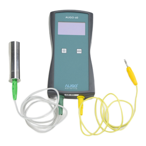
ӹAIJGO-61 resistance meter
ӹElectrodes (2 pieces)
ӹWires with banana plug and BNC plug ends (2 pieces)
ӹCrocodile clips (2 pieces)
ӹMini USB data cable
ӹPendrive with softwares
ӹAA batteries (4 pieces)
Sizes 93 x 185 x 35 mm (W x L x H)
Weight ca. 370 g
Test voltage 10 V, 100 V, 500 V (±5% ±2 V)
Resistance measuring range 2 Ω – 1 TΩ
Resistance measuring accuracy 2 Ω – 109 Ω: ±10%, 109 Ω – 1012 Ω ±20%
Temperature measuring range 0 °C – 45 °C
Temperature measuring accuracy ±0,3%, max. ±0,5%
Temperature measuring frequency ~ 2 s
Humidity measuring range 10 – 85% RH
Humidity measuring accuracy ±2%, max. ±3,5%
Humidity measuring frequency ~ 2 s
Stored values Resistance, temperature, humidity
Number of measurement data rows that can be stored 20 pieces
Standard weight of electrodes 2,25 ±0,25 kg
PC connection Mini USB-B
Display Graphic 128 x 64 pixel
Power supply With 4 pieces of 1,5 V AA batteries or via
USB cable
Operating time ca. 12-14 hours
Technical specications

4
About construction and use
Parts of the product
On/O button (3) With long keypress (3 sec.) you can turn the
device on and o.
Backlight button (7) With short keypress you can turn the backlight
on and o.
VSET button (6) With short keypress you can switch between the
test voltage values.
Mode button (2) With long keypress (3 sec.) you can store the
measured values.
Measure button (5) Keep the button pressed to take the
measurement. When you release it, the
measurement result remains on the display.
1
2
3
4
5
6
7
LCD display
Mode button
On/O button
Electrode connectors
VSET button
Backlight button
Measure button
8
Mini USB socket
Functions of the buttons

5
User instructions and information
Connecting accessories
Connect the instrument, cables, electrodes and, if necessary, grounding according
to the measurement method to be used.
Measurement methods
Point-to-point measurement (Rp-p)
Connect the BNC plug ends of the wires to the
instrument and the black shielding wire connectors
to the black sockets of the electrodes and the red
measuring wire connectors to the red sockets of the
electrodes.
Measurement of resistance to ground (Rg)
Connect the BNC plug ends of the wires to the
device and the connector of one of the black
shielding wires to the black socket of one of
the electrodes. To the red socket of the same
electrode, connect the red wire connected to
the black shielding wire already in use. Connect
the other red measuring wire to the ground.
The use of the other black shielding wire is not
necessary for this measurement method.
Surface resistance measurement (Rs)
Connect the BNC plug ends of the wires to the device and the
two red measuring wires to a ring electrode. (Ring electrode is
not provided in the AIJGO-61 product package.) The use of the
two black shielding wires is not necessary for this measurement
method.
Measurement of volume resistance (Rv)
Connect the BNC plug ends of the wires to the device and the
connector of one of the red measuring wires to the red socket of
one of the electrodes. Connect the other red measuring wire to
the conductive material under the measured item. The use of the
black two shielding wires is not necessary for this measurement
method.

6
Turning on
Turn on the device with the “On/O” button. After switching on, a text similar to the
following appears on the screen containing the device’s data:
AIJGO-61
RESISTANCE METER
S/N: 1234
Ver: v1.02
This is visible for 10 seconds. If you do not want to wait this time, but want to move
on faster, press any button except “On/O”. You will then see a screenshot similar to
the one below:
_____
10V
24.5°C 42.1%RH
Measuring voltage
Temperature
Place to display the
resistance value
Relative Humidity
...MEASURING...
100V
24.5°C 42.1%RH
187 MΩ
100V
24.5°C 42.1%RH
Measurement
The AIJGO-61 is suitable for measuring a wide resistance range, between 2 Ω and
1 TΩ. This also enables the measurement of equipment grounding resistance and
the resistance of ESD protective worksurfaces to ground. Thus there is no need
to use other resistance meter during ESD qualication or compliance verication
measurements.
Press and hold the “Measure” button until the measurement result is displayed. This
will remain visible until you press the “Measure” button again.
When measuring temperature and humidity, make sure that you do not cover the
sensor on the bottom of the device with your hands or other objects, and do not
place the device on a cooled or heated surface, as this may aect the measurement
results.
Storing measurement results
The measurement results can be stored by pressing and holding the “MODE” button,
after this a message is shown on the display for 3 seconds. If any blank space is still
available in the measurement list, a message similar to the following will be displayed:

VALUES STORED
LIST POS: x
7
The value of x indicates the position in the measurement list where the measured
resistance value and the associated temperature and humidity data are placed. The
list can contain up to 20 measurement positions. Once full, it is not possible to store
any more results. In this case, the following message will appear after a long press on
the “MODE” button:
LIST FULL
When the list is full, it is only possible to store another measurement result after
deleting the list, which can only be done by a computer.
Management of measurement results on computer
An AIJGO-61 product can be connected to a computer with a USB-A to mini USB-B
cable. To manage the measurement results on a computer, the driver program
supplied with the device must be installed, which assigns a virtual serial port to the
resistance meter. To do this, run the application „CDM v2.08.30 WHQL Certied.exe”
as administrator which is on the supplied pendrive (Right mouse button -> Run as
administrator). Once the installation is completed, launch the terminal program
(termite-3.1.exe), also available from the pendrive. The application will start after the
installation. You can use the shortcut in the Start menu to launch it later (it is listed
under the name “Termite”).
When the terminal program is started, a window similar to the following picture
appears:

8
Click on the “Settings” button and congure your program as follows:
The “Port” eld must contain the virtual serial port number assigned to the device
for proper operation.
Two commands can be used in the program to manage the stored data of an
AIJGO-61 product, these are “LIST” and “DELETE”. The commands can be sent by
pressing the “enter” key after typing them. The following is a picture of the terminal
program after the user has retrieved a stored list with the “LIST” command, deleted it
with the “DELETE” command, and then started a new retrieval with a repeated “LIST”
command.
The listed data can be selected in the terminal program window and copied to
somewhere else if necessary.

9
Maintenance
Replacement of the batteries
If the batteries are discharged, a screenshot similar to the following will be displayed:
31.6 kΩ
LO W B AT TE RY
24.5°C 42.1%RH
In this case the measuring instrument is automatically set to 10 V measuring voltage.
You can remove the cover plate by unscrewing two screws on the back of the meter
to change the batteries. Be sure to place them in the correct direction to avoid
possible circuit damage.
Safety instructions
The measuring instrument uses 10 V, 100 V or 500 V measuring voltage between the
electrode connections. The output current is limited to 1 mA, nevertheless do not
touch the electrodes when measuring with the instrument.
Calibration
Calibration of the device is recommended once in every 2 years.
The images in this document are for information purposes only. The design, the accessories, the technical
specications and various details of the product can be changed. We reserve the right to sell such changed
product without notice. In case of improper use other than as described in this documentation or in case of
modication of the product which D és Tsa. Bt. has not given its written consent, our company may reject any
warranty claims.

D és Tsa. Bt.
2600 Vác, Dr. Csányi László Krt. 83.
Hungary
Tel. / Fax: +36 27 502 555
+36 27 200 835
E-mail: sales@destsa.hu
Web: www.destsa.hu
www.dlb.hu
Table of contents
Other dlb Measuring Instrument manuals