NIVELCO MicroTREK HT Owner's manual

htk4014a0600p_04
2 / 68
APPROVALS
Reference document
number
BKI ATEX, Certificate No.: BKI16ATEX0018X htk4014m0600p_03
BKI IECEx, Certificate No.: IECEx BKI 09.0001 issue No:1 htk4014a0600p_01
INMETRO, Certificate No.: DNV 14.0169 X Rev. 01 htk4014p0600p_03
Ex Russia, Certificate No.: RU C-HU.MЮ62.B.04400 htk4014o0600p_02

htk4014a0600p_04
3 / 68
GUIDED MICROWAVE LEVEL MEASUREMENT

htk4014a0600p_04
4/68
CONTENTS
1.INTRODUCTION.......................................................................................6
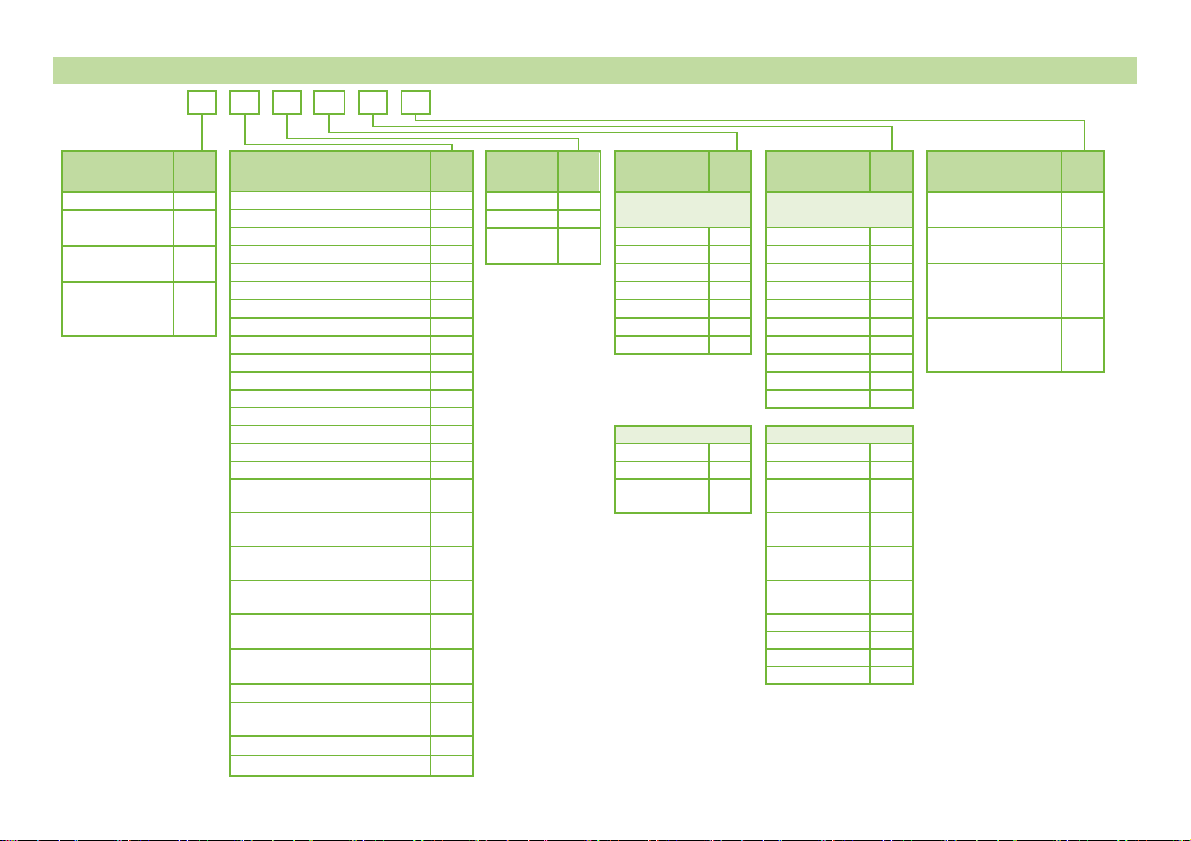
2.ORDER CODE..........................................................................................7
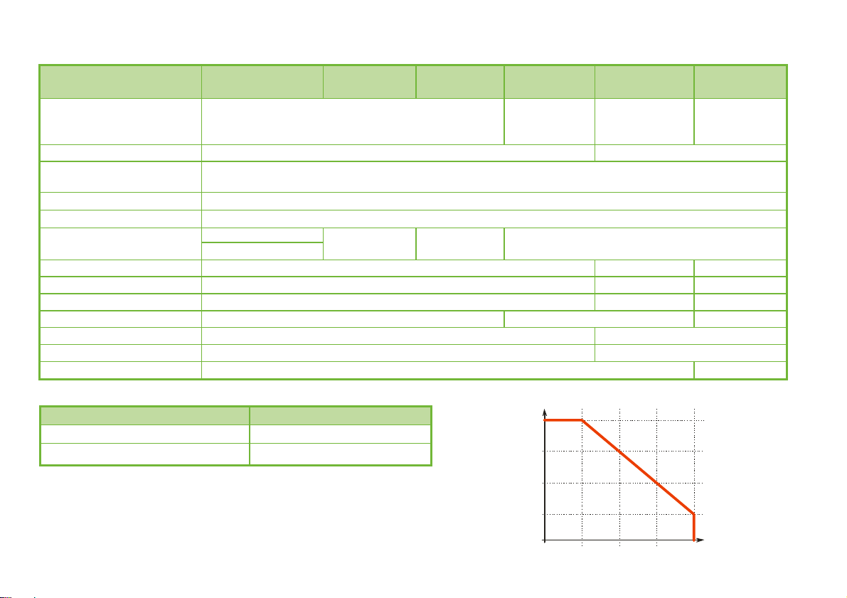
3. TECHNICAL DATA...................................................................................8
3.1.Explosion protection, ex markings, ex limit data .............................13
3.2.Accessories.....................................................................................16
3.3.Special conditions of safe use.........................................................16
3.4.Maintenance and repair ..................................................................16
4.MECHANICAL INSTALLATION.............................................................17
4.1.Handling and storage ......................................................................17
4.2.Mounting on the tank.......................................................................18
4.2.1.Installation instructions: general notes ....................................18
4.2.2.Specific installation instructions: gauge – solid applications...21
4.3.Wiring ..............................................................................................22
4.3.1.BUS (HART®) communication.................................................25
4.4.Power-on and start-up.....................................................................26
4.5.Available user interfaces.................................................................26
5.PROGRAMMING.................................................................................... 26
5.1.Programming with EView2 software............................................... 26
5.1.1.EView2 software installation and execution. .......................... 26
5.1.2.Device programming, configuration with EView2 ................... 27
5.1.3.Quick Configuration: configuration examples ......................... 37
5.2.Programming with SAP-300 display unit ........................................ 44
5.2.1.SAP-300 display unit .............................................................. 44
5.2.2.MicroTREK’s behaviour in manual programming mode ......... 45
5.2.3.Manual programming.............................................................. 46
5.3.Programming with HART® handheld (HHC) Communicator........... 47
5.3.1.Characters available for alpha-numerical data functions........ 55
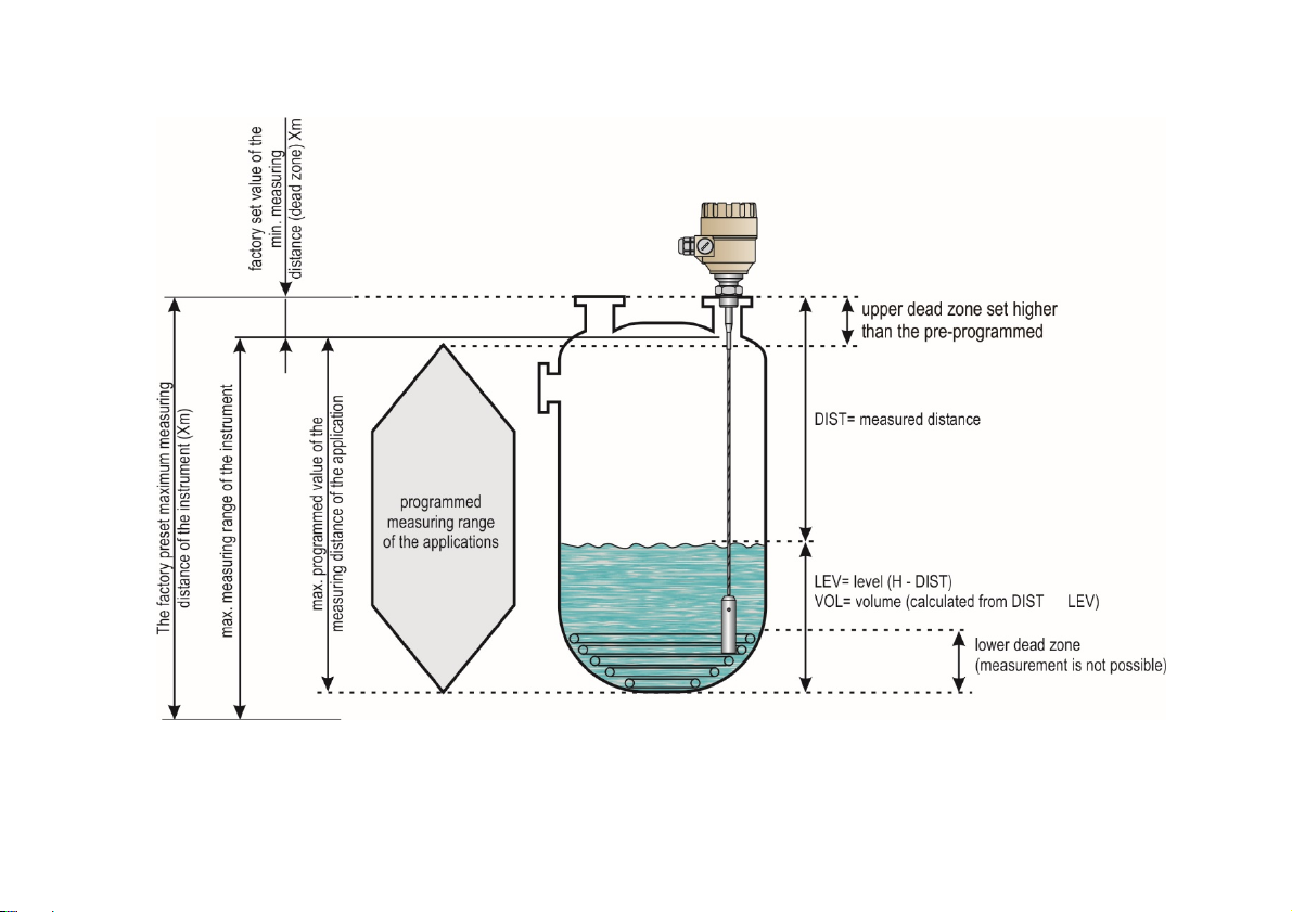
5.4.MicroTREK 2-wire T.D.R. meter characteristics............................. 55
5.4.1.Gauge operating logic when the reflection is lost ................... 57
5.4.2.Gain and voltage amplitude .................................................... 58
5.4.3.Typical signal trends ............................................................... 62
5.4.4.Automatic adjustment ............................................................. 62
5.4.5.Level measurement where there are multiple phases or layers
in the tank.......................................................................................... 64
5.5.Troubleshooting.............................................................................. 65

htk4014a600p_04
5/68

htk4014a600p_04
6/68
Thank you for choosing a NIVELCO instrument.
We are sure that you will be satisfied with our product!
1. INTRODUCTION
Application
The MicroTREK 2-wire level gauge uses the Time Domain Reflectometry (TDR) measuring principle and two-wire technology for level measurement.
It is designed for measuring distance, level and volume of liquids, pastes, slurries and powder mediums.
The device is applicable in tank, silo, rigid pipe, reaction-vessel and level reference vessel.
The device is HART®capable, it can be programmed using a HART®Handheld Communicator (HHC), a MultiCONT universal process controller and EView2 software
supplied as standard with the gauge.
Operating principle
The MicroTREK 2-wire guided microwave level transmitter uses the TDR (Time Domain Reflectometry) principle. The instrument sends low power nanosecond wide
pulses along an electrically conductive rod, cable or coaxial probe with a known propagation speed (the speed of light). As the pulse reaches the surface of the medium
or phase of two liquids (altered dielectric constant r), a part of it is reflected back to the electronic module. The efficiency of the reflected signal depends on the
dielectric constant rdifference of the mediums or layers. (From the plain surface of air-water phase the reflected signal's strength will be approx. 80% of the emitted
signal). The reflected pulse is detected as an electrical voltage signal and processed by the electronics. Level distance is directly proportional to the flight time of the
pulse. The measured level data is converted into 4 – 20 mA current and HART signals and is displayed on the LCD display. From the level data further measuring
values can be calculated such as volume and mass. The TDR technology is unaffected by the other properties of the medium as well as of the space above it.

htk4014a600p_04
7/68
2. ORDER CODE
MicroTREK H - - 2-wire guided microwave level transmitter
Type Code Probe / Proc. conn. Code Housing Code Insertion
length Code Insertion
length Code Output / Ex Code
Transmitter T Coaxial / 1" BSP A Aluminium 4 Coaxial, Rod,
Twin rod
Coaxial, Rod,
Twin rod
4 – 20 mA + HART /
Normal 4
High temperature
transmitter H Coaxial / 1" NPT B Plastic 5
Coaxial / 11/2" BSP C Stainless
steel 6 0 m (0 ft) 0 0 m (0 ft) 0 4 – 20 mA + HART /
Ex tD (ATEX, EAC) 5
Transmitter +
display B Coaxial / 11/2" NPT H 1 m (3.3 ft) 1 0.1 m (0.33 ft) 1
Rod / 1" BSP R 2 m (6.6 ft) 2 0.2 m (0.66 ft) 2 4 – 20 mA + HART /
Ex iaD (ATEX, IECEx,
EAC, INMETRO) 6
High temp.
transmitter +
display
P
Rod / 1" NPT P 3 m (10 ft) 30.3 m (1 ft) 3
Rod / 11/2" BSP S 4 m (13.1 ft) 4 0.4 m (1.32 ft) 4
Rod / 11/2" NPT Z 5 m (16.5 ft) 5 0.5 m (1.64 ft) 5 4 – 20 mA + HART /
Ex ia (ATEX, IECEx,
EAC, INMETRO)
8
Twin rod / 11/2" BSP D 6 m (20 ft) 6 0.6 m (2 ft) 6
Twin rod / 11/2" NPT E 0.7 m (2.3 ft) 7
4 mm (0.15 inch) cable / 1" BSP K 0.8 m (2.62 ft) 8
4 mm (0.15 inch) cable / 1" NPT L 0.9 m (3 ft) 9
4 mm (0.15 inch) cable / 11/2" BSP V
4 mm (0.15 inch) cable / 11/2" NPT W Cable version Cable version
8 mm (0.315) cable / 11/2" BSP N 0 m (0 ft) 0 0 m (0 ft) 0
8 mm (0.315) cable / 11/2" NPT J 10 m (32.8 ft) 1 1 m (3.3 ft) 1
4 mm (0.15 inch) twin cable /
11/2" BSP T 20 m (56.6 ft) 2 2 m (6.6 ft) 2
4 mm (0.15 inch) twin cable /
11/2" NPT U 3 m (10 ft) 3
4 mm (0.15 inch) FEP coated cable
1" BSP F 4 m (13.1 ft) 4
4 mm (0.15 inch) FEP coated cable
1" NPT G 5 m (16.5 ft) 5
4 mm (0.15 inch) FEP coated cable
/ DN40 TriClamp X 6 m (20 ft) 6
7 m (23 ft) 7
4 mm (0.15 inch) FEP coated cable
/ DN40 Milch Y 8 m (26.3 ft) 8
9 m (30 ft) 9
PFA fully coated rod / DN50 Q
4 mm (0.15 inch) FEP fully coat.
cable / DN50 M
PP fully coated rod / DN50 I
PFA fully coated rod / 11/2" TriClamp O

htk4014a600p_04
8/68
3. TECHNICAL DATA
GENERAL DATA
Type Plastic Housing
H–5–4
Aluminium Housing
H–4–4, –5, –6, –8
Stainless Steel Housing
H–6–4, –5, –6, –8
Input
data
Measured values Between the reference point of the unit and reflection pane (material surface), distance, level and volume
Measuring range Depends on the type of the probe and the properties of the measured medium (see: Technical data on the “probes” chart)
Types of probes and technical data Coaxial, twin cable, mono cable, twin rod and mono rod probes (see: Technical data of the probes table)
Housing Plastic PBT Paint coated aluminium Stainless steel (KO35)
Medium temperature -30 °C … +200 °C (-22 °F … +392 °F) (see Technical data – MEDIUM TEMPERATURE table)
Medium pressure -1 – 40 bar (-0.1 – 4 MPa [-14 – 580 psig]) (see Technical data – MEDIUM PRESSURE diagram)
Ambient temperature -30 °C …+60 °C (-22 °F … +140 °F), with display: -20 °C … +60 °C (-4 °F … +140 °F)
Sealing FPM (Viton), optional for high temperature version: FFKM Perfluoroelastomer (Kalrez6375), EPDM
Ingress protection IP67 (NEMA 4 – 4X)
Power supply 18 – 35 V DC, nominal 24 V DC, Ex version: 18 – 28 V, protection against surge transients
Output
data
Output signals
Analogue: 4 – 20 mA, (3.9 – 20.5 mA) passive output, error signal: 22 mA
BUS: serial line, HARTinterface, terminal resistor max. 750 Ω
Display: SAP-300 plug-in LCD matrix
Accuracy* For liquids: 5 mm (0.2 inch); For probe length L ≥10 m (L ≥33 ft): 0.05% of the range
For solids: 20 mm (0.8 inch ); For probe length L ≥10 m (L ≥33 ft): 0.2% of the range
Resolution 3 A
Electrical connection 2x M20x1.5 metal cable glands for Ø7 – 13 mm (Ø0.3 – Ø0.5 in) cable, or 2x M20x1.5 plastic cable glands for Ø6 – 12 mm (Ø0.23 – 0.47 in)
cable wire cross section: 0.5 – 1.5 mm2(AWG15) (shielded cable is recommended) + internal thread for 2x ½" NPT cable protective pipe
Electrical protection Class III
Mass (housing) 1.5 kg (3.3 lb) 2.4 kg (5.3 lb) 4.1 kg (9 lb)
* Under ideal reflection and stabilised temperature conditions.

htk4014a600p_04
9/68
TECHNICAL DATA OF THE PROBES
Type
HK, HL,
HV, HW
––
HR, HP
––
HS, HZ
––
HN, HJ
––
HT, HU
––
HD, HE
––
HA, HB,
HC, HH
––
Description 4 mm cable
(0.15 inch) Rod 8 mm cable
(0.3 inch)
4 mm twin cable
(0.15 inch) Twin rod Coaxial
Max. measuring
distance 24 m (80 ft) 3 m (10 ft) 6 m (20 ft) 24 m (80 ft) 3 m (10 ft) 6 m (20 ft)
Min. measuring
distance
r = 80 / r = 2.4
0.3 m / 0.4 m (1 ft / 1.3 ft) 0.15 m / 0.3 m (0.5 ft / 1 ft) 0 m (0 ft)
Min. distance to
objects 600 mm (Ø2 ft) 200 mm (Ø 0.65 ft) 0 mm (0 ft)
Min. medium r 2.1 1.8 1.4
Process connection
1" BSP 1" BSP 11/2" BSP 1" BSP
1" NPT 1" NPT
11/2" BSP 1" NPT 11/2" NPT 11/2" BSP
11/2" NPT 11/2" NPT
Probe material 1.4401 1.4571 1.4401 1.4571
Nominal diameter
of probe
4 mm
(0.15 inch)
8 mm
(0.3 inch)
14 mm
(0.55 inch)
8 mm
(0.3 inch)
4 mm
(0.15 inch)
8 mm
(0.3 inch)
28 mm
(1.1 inch)
Mass 0.12 kg/m
(0.08 lb/ft)
0.4 kg/m
(0.25 lb/ft)
1.2 kg/m
(0.8 lb/ft)
0.4 kg/m
(0.25 lb/ft)
0.24 kg/m
(0.16 lb/ft)
0.8 kg/m
(0.5 lb/ft)
1.3 kg/m
(0.85 lb/ft)
Separator material –
PFA,
welded on the
cable
PTFE-GF25
if length
> 1.5 m (5 ft)
PTFE,
If length
>1.5 m (5 ft)
Weight dimensions Ø25 x 100 mm
(Ø1 x 4 inch) – Ø40 x 260 mm
(Ø1.5 x 10 inch)
Ø40 x 80 mm
(Ø1.5 x 3 inch) –
Weight material 1.4571 (316Ti) – 1.4571 (316Ti) 1.4571 (316Ti) –

htk4014a600p_04
10/68
TECHNICAL DATA OF THE COATED PROBES
Type HF, HG
––HTX––HTY––HTM––HTQ––HTI––
Description 4 mm (0.15 inch) FEP coated cable
4 mm (0.15 inch)
fully FEP coated
cable
Fully PFA coated
rod
Fully PP coated
rod
Max. measuring distance 24 m (80 ft) 3 m (10 ft)
Min. measuring distance
r = 80 / r = 2.4 0.3 m / 0.4 m (1 ft / 1.3 ft)
Min. distance to objects 600 mm (Ø2 ft)
Min. medium r2.1
Process connection 1" BSP DN40 TriClamp DN40 Milch DN50
1" NPT
Probe material 1.4401 (316) / FEP 1.4571 (316) / PFA 1.4571 (316) / PP
Nominal diameter of the probe 6 mm (0.23 inch) 12 mm (0.5 inch) 16 mm (0.62 inch)
Mass 0.16 kg/m (0.1 lb/ft) 0.5 kg/m (0.33 lb/ft) 0.6 kg/m (0.4 lb/ft)
Fillet coating material – PFA PP
Weight dimensions Ø25 x 100 mm (Ø1 x 4 inch) –
Weight material 1.4571 (316Ti) –
Max. medium temperature +150 °C (+302 °F) +60 °C (+140 °F)
MEDIUM TEMPERATURE TABLE MEDIUM PRESSURE DIAGRAM
Type Flange temperature
200°C
140°C
80°C
20°C
-30°C -1 bar 16 bar 24 bar 32 bar 40 bar
Transmitter -30 °C … +90 °C (-22 °F … +194 °F)
High temp. HHor HPtransmitter -30 °C … +200 °C (-22 °F … +392 °F)

htk4014a600p_04
11/68
DIMENSIONS
HTK, HTL, HTV,
HTW––
HTR, HTP
––
HTS, HTZ
––
HTN, HTJ
––
HTT, HTU
––
HTD, HTE
––
HA, HB, HC, HH
––
HTF, HTG
––HTX––HTY––HTM––HTQ––HTI––

htk4014a600p_04
12/68
1 Housing
2 Cable gland
3 High temp. connection
4 Mono cable probe
5 Weight
6 Twin cable probe
7 Twin cable separator
8 Twin rod separator
9 Twin rod probe
10 Mono rod probe
11 Grounding screw
12 Process connection
13 Coaxial probe

htk4014a600p_04
13/68
3.1. EXPLOSION PROTECTION,EX MARKINGS,EX LIMIT DATA
3.1.1. ATEX Approval No.: BKI16ATEX0018X
For intrinsically safe [Ex ia] protection modes
Type
Metal housing
with SAP display
HB––6, –8Ex
Metal housing
without SAP display
HT––6, –8Ex
High temperature version with metal
housing with SAP display
HP––6, –8Ex
High temperature version with metal
housing without SAP display
HH––6, –8Ex
Ex marking (ATEX) II 1G Ex ia IIB T6…T3 Ga II 1G Ex ia IIC T6…T3 Ga II 1G Ex ia IIB T6…T3 Ga II 1G Ex ia IIC T6…T3 Ga
II 1D Ex ia IIIC T85°C…T110°C Da II 1D Ex ia IIIC T85°C…T180°C Da
Ex power supply,
Intrinsically safety data Ci ≤10 nF, Li ≤10 H, Ui ≤30 V,
Ii ≤140 mA, Pi ≤1 W
Ci ≤10 nF, Li ≤10 H, Ui ≤30 V,
Ii ≤100 mA, Pi ≤0,75 W
Ci ≤10 nF, Li ≤10 H, Ui ≤30 V,
Ii ≤140 mA, Pi ≤1 W
Ci ≤10 nF, Li ≤10 H, Ui ≤30 V,
Ii ≤100 mA, Pi ≤0,75 W
For dust protection by enclosure [Ex tD] protection modes
Type
Metal housing
HB––5Ex
HT––5Ex
High temperature version with metal housing
HP––5Ex
HH––5Ex
Ex marking (ATEX) II 1/2 D Ex ta/tb IIIC T85°C…T110°C Da/Db II 1/2 D Ex ta/tb IIIC T85°C…T180°C Da/Db
Ex power supply,
Intrinsically safety data Ui = 12.5 V DC – 30 V DC
3.1.2. IECEx Approval No.: IECEx BKI 09.0001 Issue No: 1
For intrinsically safe [Ex ia] protection modes
Type
Metal housing
with SAP display
HB––6, –8Ex
Metal housing
without SAP display
HT––6, –8Ex
High temperature version with metal
housing with SAP display
HP––6, –8Ex
High temperature version with metal
housing without SAP display
HH––6, –8Ex
Ex marking
(IECEx, INMETRO)
Ex ia IIB T6…T3 Ga IIC T6…T3 Ga
Ex ia IIB T6…T3 Ga Ex ia IIC T6…T3 Ga
Ex ia IIIC T100°C Da
Ex power supply,
Intrinsically safety data Ci ≤10 nF, Li ≤10 H, Ui ≤30 V,
Ii ≤140 mA, Pi ≤1 W

htk4014a600p_04
14/68
3.1.3. INMETRO Approval No.: DNV 14.0169 X – Rev. 01.
For intrinsically safe [Ex ia] protection modes
Type
Metal housing
with SAP display
HB––6, –8Ex
Metal housing
without SAP display
HT––6, –8Ex
High temperature version with metal
housing with SAP display
HP––6, –8Ex
High temperature version with metal
housing without SAP display
HH––6, –8Ex
Ex marking
(IECEx, INMETRO)
Ex ia IIB T6…T3 Ga IIC T6…T3 Ga
Ex ia IIB T6…T3 Ga Ex ia IIC T6…T3 Ga
Ex ia IIIC T100°C Da
Ex power supply,
Intrinsically safety data Ci ≤10 nF, Li ≤10 H, Ui ≤30 V,
Ii ≤140 mA, Pi ≤1 W
3.1.4. EAC Approval No.: RU C-HU.MЮ62.B.04400
For intrinsically safe [Ex ia] protection modes:
Type
Metal housing
with SAP display
HB––6, –8Ex
Metal housing
without SAP display
HT––6, –8Ex
High temperature version with metal
housing with SAP display
HP––6, –8Ex
High temperature version with metal
housing without SAP display
HH––6, –8Ex
Ex marking (EAC) 0Ex ia IIB «T6…T3» Ga X 0Ex ia IIC «T6…T3» Ga X 0Ex ia IIB «T6…T3» Ga X 0Ex ia IIC «T6…T3» Ga X
Ex ia IIIC «T85°C…T110°C» Da X Ex ia IIIC «T85°C…T180°C» Da X
Ex power supply,
Intrinsically safety
data
Ci ≤10 nF, Li ≤10 H, Ui ≤30 V,
Ii ≤140 mA, Pi ≤1 W
Ci ≤10 nF, Li ≤10 H, Ui ≤30 V,
Ii ≤100 mA, Pi ≤0,75 W
Ci ≤10 nF, Li ≤10 H, Ui ≤30 V,
Ii ≤140 mA, Pi ≤1 W
Ci ≤10 nF, Li ≤10 H, Ui ≤30 V,
Ii ≤100 mA, Pi ≤0,75 W
For dust protection by enclosure [Ex tD] protection modes:
Type
Metal housing
HB––5Ex
HT––5Ex
High temperature version with metal housing
HP––5Ex
HH––5Ex
Ex marking (ATEX) Ex ta IIIC «T85°C…T110°C» Da X
Ex tb IIIC «T85°C…T110°C» Db X
Ex ta IIIC «T85°C…T180°C» Da X
Ex tb IIIC «T85°C…T180°C» Db X
Ex power supply,
Intrinsically safety data Ui = 12.5 – 30 V DC

htk4014a600p_04
15/68
3.1.5. Temperature data for ex certified models
Temperature limit data for ATEX and IECEx approvals
Temperature data
Explosive gas atmosphere Explosive dust atmosphere
Aluminium and stainless-steel housing
H––8Ex
Aluminium and stainless-steel housing
H––5, –6Ex
High temperature
High temperature
HH––8Ex
HP––8Ex
HH––6Ex
HP––6Ex
Ex ia IIC, Ex ia IIB Ex ia IIIC, Ex ta/tb IIIC
Maximum permissible medium temperature +80 °C
(+176 °F)
+90 °C
(+194 °F)
+100 °C
(+212 °F)
+180 °C
(+356 °F)
+80 °C
(+176 °F)
+90 °C
(+194 °F)
+100 °C
(+212 °F)
+180 °C
(+356 °F)
Maximum permissible surface temperature at
the process connection
+70 °C
(+158 °F)
+90 °C
(+194 °F)
+100 °C
(+212 °F)
+175 °C
(+347 °F)
+75 °C
(+167 °F)
+90 °C
(+194 °F)
+100 °C
(+212 °F)
+175 °C
(+347 °F)
Maximum permissible ambient temperature ≤60 °C (≤140 °F)
Temperature class T6 T5 T4 T3 T85°C T100°C T110°C T180°C
Temperature limit data for IECEx and INMETRO approvals
Temperature data
Explosive gas atmosphere Explosive dust atmosphere
Aluminium housing
H–4–8Ex Aluminium housing
High temperature
HT–4–6Ex
HB–4–6Ex
HH–4–8Ex
HP–4–8Ex
Ex ia IIC, Ex ia IIB Ex ia IIIC
Maximum permissible medium temperature ≤85 °C
(≤185 °F)
≤100 °C
(≤212 °F)
≤135 °C
(≤275°F)
≤200 °C
(≤392 °F)
+90 °C
(+194 °F)
Maximum permissible ambient temperature ≤60 °C (≤140 °F)
Temperature class T6 T5 T4 T3 T100°C

htk4014a600p_04
16/68
3.2. ACCESSORIES
Warranty Card 2 pcs M20x1.5 cable glands
User’s and Programming Manual SAP-300 display module (option)
EU declaration of Conformity Flat seal (where justified)
EView2 software CD
3.3. SPECIAL CONDITIONS OF SAFE USE
The device with SAP display must not be operated in Ex ia IIC environment!
Transmitters with spark-free mode should be connected exclusively to a certified circuit with [Ex ia Ga] IIC or [Ex ia Ga] IIB safety mode, applying maximum values
detailed in the 3.1 section.
The metallic housing of the device is to be connected to the network with identical potential (EP).
The aluminium content of the die-cast aluminium alloy case exceeds the limit, which requires the device is protected against any possible sources of spark or ignition
resulted by impact or friction effects.
If the device is equipped with a coated sensor, then it should only be operated in a circuit with Ex ia IIB protection mode.
The size of the status window of devices with Ex ia IIC T6…T3 Ga protection level exceeds the limit; therefore, the device is to be protected against effects may cause
electrostatic charging.”
3.4. MAINTENANCE AND REPAIR
MicroTREK does not require maintenance on a regular basis.
In some very rare instances however, the probe may need a cleaning from deposited material.
This must be carried out gently, without damaging the probe.
Repairs during or after the warranty period should be carried out exclusively by the Manufacturer.
The equipment sent back for repair is to be cleaned or neutralised (disinfected) by the User prior to despatch.

htk4014a600p_04
17/68
4. MECHANICAL INSTALLATION
4.1. HANDLING AND STORAGE
When manually carrying, hold it with both hands, or when powerlifted, pay attention to
handle the device with care, lifting it by the converter housing. If necessary, use lifting
gear. No attempt should be made to lift the instrument by its probe.
Caution: The probe is a critical gauge component. Do not damage – Handle with care!
A
voiding blows
–
avoid hard blows, jolts, impacts, etc.
Caution: fragile electronics
A
void bending (single rod and coaxial probes)
–
Support the probe to avoid bending.
A
void cable kinks and fraying
Do not coil the cable with less than 400 mm (16 inch) in diameter. Cable kinks
or fraying will cause measurement errors.
Storage temperature

htk4014a600p_04
18/68
4.2. MOUNTING ON THE TANK
4.2.1. Installation instructions: general notes
Prior to installation the fittings and the shape of the tanks are to be taken into account. Nozzle position in relation to the tank walls and other objects inside the tanks.
(Warning: this free area will depend on the probe type selected: refer to later on in this section) design of the roof of the tank i.e. floating, concrete, integral, etc;
and base, i.e. conical, etc. Before installing it, please remember to: Disconnect the power supply, the gauge may be installed when the tank contains the medium.
Threaded process connections Nozzle height Nozzles penetrating into tank
The simplest and most economic way is to mount
the MicroTREK 2-wire directly on the tank with
the 1" (1½") BSP or 1" (1½") NPT threaded
connection.
Do not fit a nozzle longer than its diameter,
especially for single probes and powder applications.
h ≤Ød, where
h = nozzle height and
Ød = nozzle diameter
Contact NIVELCO if this relationship is not feasible.
Caution: Do not use nozzles that
penetrate into the tank. This will disturb the
emitted pulse.

htk4014a600p_04
19/68
Installation of two devices Process connection and entry pipe Stilling wells
If two devices to be used on the same
tank, these should be mounted at a
distance of at least 2 m (6.5 ft) from each
other. If this is ignored, interferences from
the electromagnetic (EM) fields generated
by both instruments may cause
measurement errors.
Coaxial probes: the outer shell of the
probe contains the EM field: no minimum
distance required.
Caution: Do not put the nozzle close to the entry
pipe.
Pouring the medium directly onto the probe will give
false readings.
Install deflector plate if impossible to distance gauge
from entry pipe.
Tanks with floating roofs for petrochemical applications:
Use a stilling well.

htk4014a600p_04
20/68
Probes: entanglement, straightness and tank bottom clearance Agitator in the tank
Cable probes must be straight once inserted into the tank.
They must also be far from other objects (e.g. mixers) to avoid
entanglement.
In order to maintain the gauge’s operating characteristics, it is
recommended to avoid touching the tank bottom with the
counterweights (for cable probes) or probe end (other types).
Avoid mounting near objects (discontinuities) inside the tank that
influence the probe’s EM (electromagnetic) field
Install the gauge far from protruding objects such as: heating tubes,
sudden changes in tank cross-section, tank wall reinforcements and
beams, weld lines and dip-stick pipes, etc…
No electromagnetic field outside the reference chamber.
When measuring liquids, the use of a stilling well or reference chamber is favourable
because it ensures electromagnetic protection to ensure the accurate measurement.
Use sunshade if the unit is exposed to direct sunlight.
This manual suits for next models
7
Table of contents
Other NIVELCO Measuring Instrument manuals

NIVELCO
NIVELCO NIVOCONT User manual

NIVELCO
NIVELCO NIVOFLIP MAK-100 Series User manual

NIVELCO
NIVELCO UNICONT PDF 01-2 Series Assembly instructions

NIVELCO
NIVELCO THERMOCONT TFP Series User manual

NIVELCO
NIVELCO NIVOROTA EL 7 Series User manual

NIVELCO
NIVELCO NIPRESS D-400 Series User manual

NIVELCO
NIVELCO PiloTREK W-100 Owner's manual

NIVELCO
NIVELCO NIVOTRACK MT 2 Series User manual

NIVELCO
NIVELCO UNICONT PDF Assembly instructions

NIVELCO
NIVELCO NIVOSONAR SLM-308 User manual