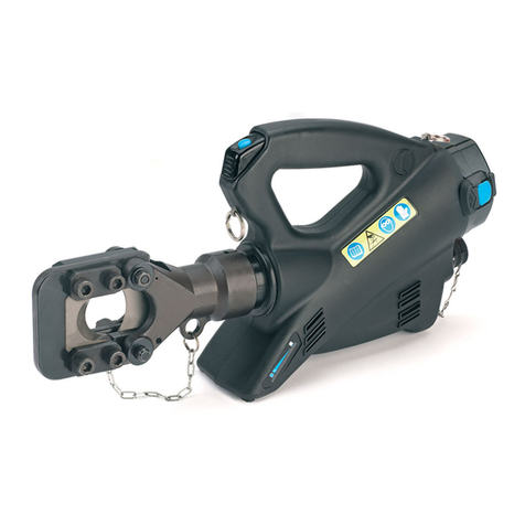
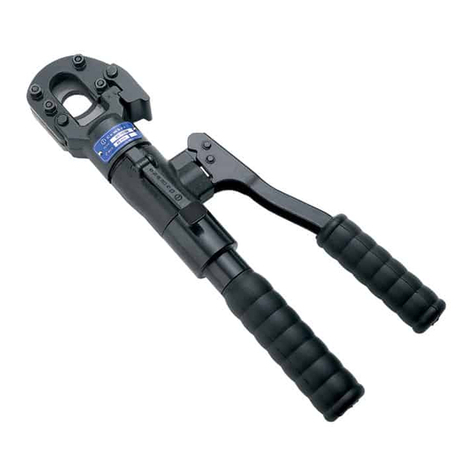
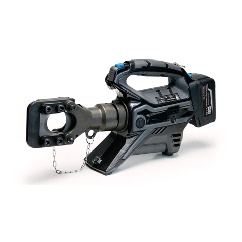
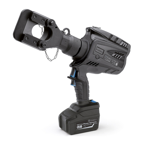
Cembre B-TC550NA User manual

1
OPERATION AND MAINTENANCE MANUAL
17 M 216 U
BATTERY OPERATED HYDRAULIC
CUTTING TOOL
B-TC550A B-TC550NA
ENGLISH

2
7
FIG. 1b
Makita battery
1
1
Low battery
5
adhesive tape
3
13
17
16
5
FIG. 2
FIG. 3
FIG. 4
FIG. 5
18
12
2
4
2
2
17
15
FIG. 1a
7
Metabo
Battery

3
1
LED WORKLIGHT
2
LOCKING PIN
3
UPPER BLADE
4
LOWER BLADE
5
OPERATING BUTTON
6
PRESSURE RELEASE BUTTON
7
BATTERY RELEASE
8
BATTERY
9
RING FOR SHOULDER STRAP
10
BATTERY ADAPTER
FIG. 6
1
9
5
6
7
2
1
4
3
10
8
1
9
5
6
8
2
1
4
3
7
B-TC550A B-TC550NA

4
– Before using the tool, carefully read the instructions in this manual.
– Keep hands clear of cutting blades.
– Always wear safety glasses and gloves when operating this tool.
WARNING SYMBOLS
– User information applies in member states of the European Union
(Directives 2011/65/EU and 2012/19/EU), see page 9.
Tool
Battery
– Never throw batteries into re or water.
– Always recycle the batteries.
– Do not discard batteries into domestic refuse or waste disposal.

5
1. GENERAL CHARACTERISTICS
(1) Directive 2006/42/EC, annexe 1, point 1.7.4.2 letter u
LpA
= weighted continuous acoustic pressure level equivalent.
LpCPeak
= maximum value of the weighted acoustic displacement pressure at the work place.
LWA
= acoustic power level emitted by the machine.
(2) Directive 2006/42/EC, annexe 1, point 2.2.1.1
Weighted root mean square in frequency of the acceleration the upper limbs are exposed to for each biodynamic
reference axis. Tests carried out in compliance with the indications contained in EN ISO 5349-1/2 Standard and under
operating conditions much more severe than those normally found.
B-TC550A B-TC550NA
Application range suitable for cutting Copper, Aluminium, ACSR and Steel
conductors, ropes and rods
Max. cutting diameter mm (inches) 55 (2-3/16”)
Operating pressure
bar (psi) 880 (12,700)
Dimensions mm (inches) 441 x 424 x 87
(17.5 x 16.7 x 3.4)
441 x 444 x 87
(17.5 x 17.5 x 3.4)
Weight with battery kg (lbs) 8,9 (19.6) 9,0 (19.9)
Motor V DC 18
Operating temperature °C (°F) -15 to +50 (+5 to +122)
Recommended oil ENI ARNICA ISO 32 or equivalents
Operating speed twin speed operation and automatic switching from
a rapid advancing speed of the ram to a slower, more
powerful speed
Safety maximum pressure valve
Rechargeable battery type CB1840L MAKITA BL1850B
Type V / Ah (Wh) 18 / 4.0 / (72) 18 / 5.0 (90)
Weight kg (lbs) 0,66 (1.45) 0,6 (1.3)
Acoustic noise
(1)
L
pA
dB (A)
73
L
pCPeak
dB (C) 94.5
L
WA
dB (A) 79
Vibration
(2)
m/s
2
0.575 max.
Battery charger
Input
type
V / Hz
ASC30-36 MAKITA DC18RC
115 / 60 120 / 50 - 60

6
Do not use the tool for purposes other than those intended by Cembre.
Theoperatorshouldconcentrateontheworkbeingperformedandbecarefultomaintainbalanced
working position.
Work in a clean, uncluttered area. Keep persons away from immediate work area.
Inspect the blades before each use. Do not use damaged blades.
Damaged blades can break and cause injury or damage to the tool.
Before each use, verify the integrity of the tool; replace any worn, possibly damaged or missing
parts with original Cembre spares.
Wear eye protection. Metal chips can y from blades when cutting.
Pay attention when cutting short, free pieces of steel rod or rope as they may y o dangerously,
causing injury to the operator or persons nearby.
Do not cut live cables or conductors.
The tool is unsuitable for continuous use and should be allowed to cool down following uninter-
rupted, successive cutting operations; for instance, having exhausted a fully charged battery in
one session, delay battery replacement for a few minutes.
Protect thetoolfrom rainand moisture.Water willdamagethe tooland battery. Electro-hydraulic
tools should not be operated in pouring rain.
The part reference includes the following:
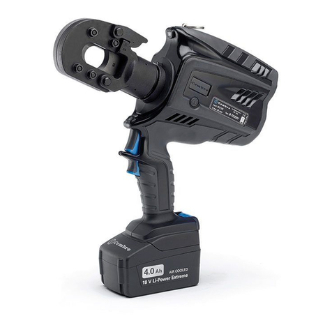
Hydraulic cutting tool (B-TC550NA is tted with adapter to use Makita battery).
Li-Ion rechargeable battery (2 pcs) (model depends on the tool version).
Battery charger (model depends on the tool version).
Shoulder strap.
Carrying case.
USB cable (Ref. to § 5).
2. INSTRUCTIONS FOR USE
The tool can be easily carried using either the handle or the shoulder strap attached to ring (9)
(Ref. to Fig. 6).
Before starting any work, check the battery charge (Ref. to § 2.7) and recharge if necessary,
Refer to the manufacturer's instructions for the correct use of battery and battery charger.
To replace the battery, remove it by pressing the release button (7) (Ref. to Fig. 1a and 1b),
B-TC550A: in the g. 1a press the release button (7) and slide the battery out unlocking it.
B-TC550NA: in the g. 1b press the release buttons (7) and slide the battery out unlocking it.
Insert a charged battery by sliding it into the guides until it locks.
2.1) Head rotation
For ease of operation, the tool head can rotate through 180°, allowing the operator to work in the
most comfortable position (Ref. to Fig. 2 and 3).
Do not attempt to rotate the head when the hydraulic circuit is pressurised.
WARNING

7
2.2) Setting
Insert the conductor between the blades, up to the desired cutting point (Ref. to Fig. 2).
To cut short pieces of steel or ACSR ropes, it is suggested to tie or wrap rope with adhesive or
duct tape around the area to be cut and at its end (Ref. to Fig. 2), so to limit the projection of
steel fragments which could damage or hurt the operator.
For a running conductor, remove the locking pin (4) and open the tool head.
Fully retract the lower blade (3) before attempting to open the tool head (Ref. to § 2.6).
With the conductor on the lower blade (3), close the tool head and fully insert the locking pin (4)
(Ref. to Fig. 3).
Before commencing the cutting operation ensure that the pin (4) is fully secured: partial
closure may damage the tool head.
2.3) Blade advancement
Operate the push-button (5) (Ref. to Fig. 2) to activate the motor-pump, the ram will gradually
move forward until the lower blade (3) touches the conductor.
To halt the advancement, release the push-button (6) and the motor will cut out.
Make sure the blade is exactly positioned on the desired cutting point otherwise re-open the
blade following instructions as per § 2.6 and reposition it.
2.4) Cutting
Firmly hold the tool and operate the push-button (5) to gradually move the lower blade (3) to
cut through the conductor.
When the cut is performed, release the push-button (5), otherwise after the maximum pressure
relief valve has activated the motor will stop automatically.
2.5) LED Worklights
Whilst the tool is in operation, the work area is illuminated by two high luminosity LED Worklights
that switch o automatically at the end of the cycle.
2.6) Blade retraction
By operating the pressure release button (6), the ram will retract and open the blades.
2.7) Battery status
The battery is equipped with LED indicators that indicate the
remaining battery life at any time by pressing the adjacent but-
ton (P):
4 LEDs illuminated: fully charged
2 LEDs illuminated: 50 % capacity
1 LED flashing: minimum charge, replace the battery
Worklights(1)illuminatedcombinedwithanalarmaudible
when the operating button (5) is pressed (Ref. to Fig. 6),
indicate that the battery voltage has dropped below a minimum safety threshold; under
these conditions the tool will not start, and it is necessary to recharge or replace the battery.
The approximate time to fully recharge a battery is about 80 minutes.
P

8
After each working cycle, and after the extraction of the battery from the tool, an integrated
battery cut-o device will operate after 70 s approx. Then the LED nearest to button (P) will
ash 5 times each 14 s approx. The battery will be reactivated when it is reintroduced into
the tool and the operating button is pressed.
2.8) Using the battery charger
Carefully follow the instructions in the battery charger user manual.
3. MAINTENANCE
The tool is robust, completely sealed, and requires very little daily maintenance. Compliance with
the following points, should help to maintain its optimum performance:
3.1) Thorough cleaning
Dust, sand and dirt are a danger for any hydraulic device. Every day, after use, the tool must be
wiped with a clean cloth taking care to remove any residue, especially close to pivots and move-
able parts.
Do not use hydrocarbons to clean the rubber parts.
Regularly lubricate the moving parts and pivot pins of the head with a few drops of oil.
3.2) Storage case
When not in use, the tool should be stored and transported in the plastic case, to prevent damage.
The case, type VAL-P40, is suitable for storing the tool and accessories.
VAL-P40: Size 520x432x126 mm (20.5x17.0x5.0 inches). Weight 2,6 kg (5.7 lbs).
3.3) Routine maintenance
When the tool reaches the predetermined number of hours worked, it will signal that routine
maintenance is recommended.
The tool will continue to work however 15 sec. after use an alarm comprising 3 beeps com-
bined with illumination of the worklights will signal that its return to Cembre for service is
recommended (see § 6).
4. BLADE REPLACEMENT (Ref. to Fig. 5)
When changing blades, the battery must rst be removed from the tool.
After extended use, the blades may break or loose their cutting edge.
Replace the blades as follows:
Lower blade
– Remove locking pin (2), and open the tool head completely.
– Operate the tool to advance the lower blade (4) and remove the battery.
– Eject two split pins (12) from the ram (13) to release the blade (4).
– Remove the broken blade from the ram, insert the new blade and t with two split pins.
Before closing the tool head, push the release button (6) and fully retract the lower blade,
otherwise the tool head assembly may hit and damage, the lower blade.
Upper blade
– With the lower blade (3) fully retracted, the tool head closed and the locking pin (4) fully secured,
hold the head by the blade spacer (15) in a bench vice with screws (16) facing upwords.
9
– With an 6 mm allen key, unscrew 4 screws (16), remove the two holding plates (17) and the upper
blade (2).
– Insert the new blade, noting the position of the cutting edge bevel.
– Fit the 2 holding plates (17) and secure with 4 screws (16) with relevant washer (18).
5. CONNECTION TO COMPUTER
Thememorycardintegratedinthetoolrecordsoperatingdata fortransferviatheUSBcablesupplied.
To view and manage this data, go to www.cembre.com and register in the dedicated area, then
download the free Cembre software CEM_SWBT01.
Keeping the Firmware of the tool updated, via free of charge download from here, will optimise
the tool’s performance.
CBA-MTMK
Screw FIG. 7
B-TC550NA: To access the mini-USB
port (Ref. to g. 8) and connect the USB
cable to the computer it is necessary
to remove CBA-MTMK battery adapter.
Remove the screws (Ref. to g. 7 and 7a)
and slide the adapter out.
mini-USB
FIG. 7a
FIG. 8
B-TC550NA
USER INFORMATION in accordance with “Directives 2011/65/EU and 2012/19/EU.“
The ‘Not in the bin’ symbol above when shown on equipment or packaging means that
the equipment must, at the end of its life, be disposed of separately from other waste.
The separate waste collection of such equipment is organised and managed by the manufacturer.
Users wishing to dispose of such equipment must contact the manufacturer and follow the prescribed
guidelines for its separate collection. Appropriate waste separation, collection, environmentally compat-
ible treatment and disposal is intended to reduce harmful environmental eects and promote the reuse
and recycling of materials contained in the equipment. Unlawful disposal of such equipment will be sub-
ject to the application of administrative sanctions provided by current legislation.
–
Following information applies in member states of the European Union:

10
6. CUTTING RANGE
MAX CUTTING DIAMETER
Steel
≤ 30
≤ 16
≤ 25
≤ 60
MATERIAL
≤ 41
≤ 20
≤ 34
55
≤ 42
Multi-strand Steel
(strands qty. ≥ 200)
≤ 180 22
Steel
≤ 180
≤ 180
50
(*)
26 x 2,50 + 7 x 1,95 : ø = 15,85
26 x 3,06 + 7 x 2,38 : ø = 19,38
26 x 3,60 + 7 x 2,80 : ø = 22,80
54 x 3,50 + 19 x 2,10 : ø = 31,50
54 x 4,36 + 19 x 2,62 : ø = 39,20
7 x 3,0 : ø = 9,0 mm
19 x 2,1 : ø = 10,5 mm
19 x 2,3 : ø = 11,5 mm
TENSILE STRENGTH
Copper
55
55
Aluminium
Almelec
Copper
Aluminium
(*) TYPICAL EXAMPLES
(*)
(daN/mm
2) (lbs/sq.in.)
≤ 59,450
≤ 29,000
≤ 49,300
≤ 261,000
20
22
34
38,5
50
≤ 43,000
≤ 23,200
≤ 36,250
≤ 87,000
≤ 60,900
≤ 261,000
(mm) (inches)
2-3/16”
2-3/16”
2-3/16”
7 x 0.118 = ø out.0.354
19 x 0.083 = ø out. 0.413
19 x 0.091 = ø out. 0.453
(*)
≤ 261,000 0.866
26 x 0.098 + 7x 0.077 : ø out 0.624
26 x 0.120 + 7x 0.094 : ø out 0.763
26 x 0.142 + 7x 0.110 : ø out 0.897
54 x 0.138 + 19x 0.082 : ø out 1.240
54 x 0.172 + 19x 0.103 : ø out 1.543
1.968
(*)
0.787
0.866
1.338
1.515
1.968
ROPES & CONDUCTORS
RODS
83 x 0.181 + 16 x 0.110 : ø out 1.968
83 x 4,60 + 16 x 2,80 : ø = 50,00
Guy wire 7 x 4,77 :
ø
=14,30 7 x 0.188 :
ø
=0.562
Extra high
strength grade
ACSR

11

121
2
This manual is the property of
Cembre
:
any reproduction is forbidden without written permission.
7. RETURN TO Cembre FOR OVERHAUL
In the case of a breakdown contact our Area Agent who will advise you on the problem and give
you the necessary instructions on how to dispatch the tool to our nearest service Centre; if possible,
attach a copy of theTest Certicate supplied by Cembre together with the tool or ll in and attach
the form available in the “ASSISTANCE” section of the Cembre website.
cod. 6261457
www.cembre.com
Cembre Ltd.
Dunton Park
Kingsbury Road, Curdworth - Sutton Coldfield
West Midlands B76 9EB (UK)
Tel.: 01675 470440 - Fax: 01675 470220
E-mail: [email protected]
www.cembre.co.uk
Cembre S.a.r.l.
22 Avenue Ferdinand de Lesseps
91420 Morangis (France)
Tél.: 01 60 49 11 90 - Fax: 01 60 49 29 10
CS 92014 - 91423 Morangis Cédex
E-mail: [email protected]
www.cembre.fr
Cembre España S.L.U.
Calle Verano 6 y 8
28850 Torrejón de Ardoz - Madrid (España)
Teléfono: 91 4852580
Telefax: 91 4852581
E-mail: [email protected]
www.cembre.es
Cembre GmbH
Heidemannstraße 166
80939 München (Deutschland)
Telefon: 089 3580676
Telefax: 089 35806777
E-mail: [email protected]
www.cembre.de
Cembre Inc.
Raritan Center Business Park
181 Fieldcrest Avenue
Edison, New Jersey 08837 (USA)
Tel.: (732) 225-7415 - Fax: (732) 225-7414
E-mail: [email protected]
www.cembreinc.com
Cembre S.p.A.
Via Serenissima, 9
25135 Brescia (Italia)
Telefono: 030 36921
Telefax: 030 3365766
E-mail: [email protected]
www.cembre.com
IKUMA GmbH & Co. KG
Boschstraße 7
71384 Weinstadt (Deutschland)
Telefon: 7151 20536 - 60
Telefax: 7151 20536 - 80
E-mail: [email protected]
www.ikuma.de
This manual suits for next models
1
Table of contents
Other Cembre Cutter manuals

Cembre
Cembre HT-TC026Y User manual

Cembre
Cembre TC050 User manual

Cembre
Cembre HT-TC065 User manual

Cembre
Cembre B35M-TFC User manual

Cembre
Cembre B-TC250NDA User manual

Cembre
Cembre TC04N User manual

Cembre
Cembre TC 120 User manual

Cembre
Cembre TC085 User manual

Cembre
Cembre B-TC950A User manual

Cembre
Cembre TC050Y-KV User manual

Cembre
Cembre HT-TC051Y User manual

Cembre
Cembre TC050Y User manual

Cembre
Cembre B-TC065-SC User manual

Cembre
Cembre B-TC026 User manual

Cembre
Cembre B500-TFC User manual

Cembre
Cembre B-TC650NA User manual

Cembre
Cembre B-TC500 User manual

Cembre
Cembre B-TC04 User manual

Cembre
Cembre B-TC450NA User manual

Cembre
Cembre B-TC250BS User manual