5
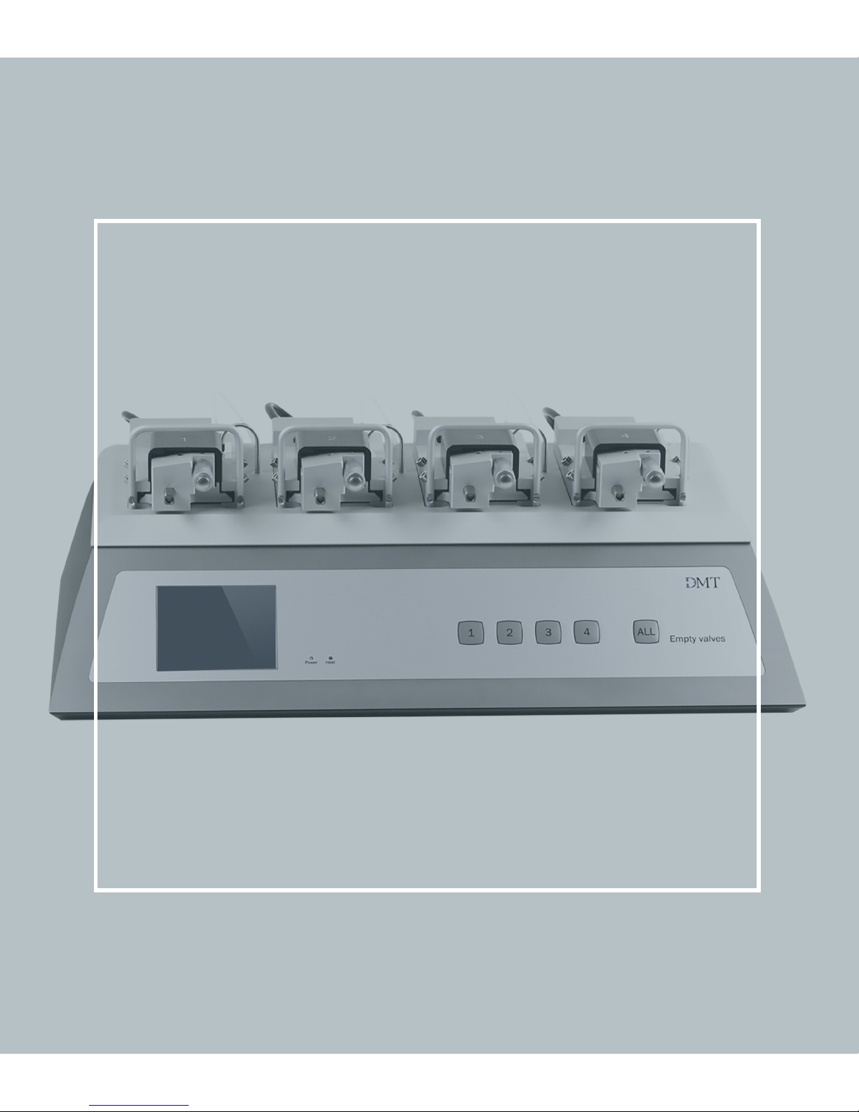
CHAPTER 2 - THE MULTI WIRE MYOGRAPH UNIT
2.1 CHANGING AND ADJUSTING THE MOUNTING SUPPORTS
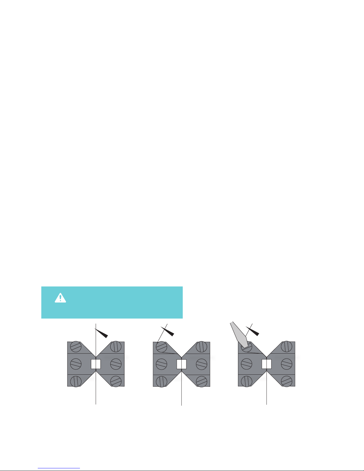
NOTE: The transducers are fragile and sensitive to mechanical strain. Be very careful
when changing or adjusting the mounting supports!
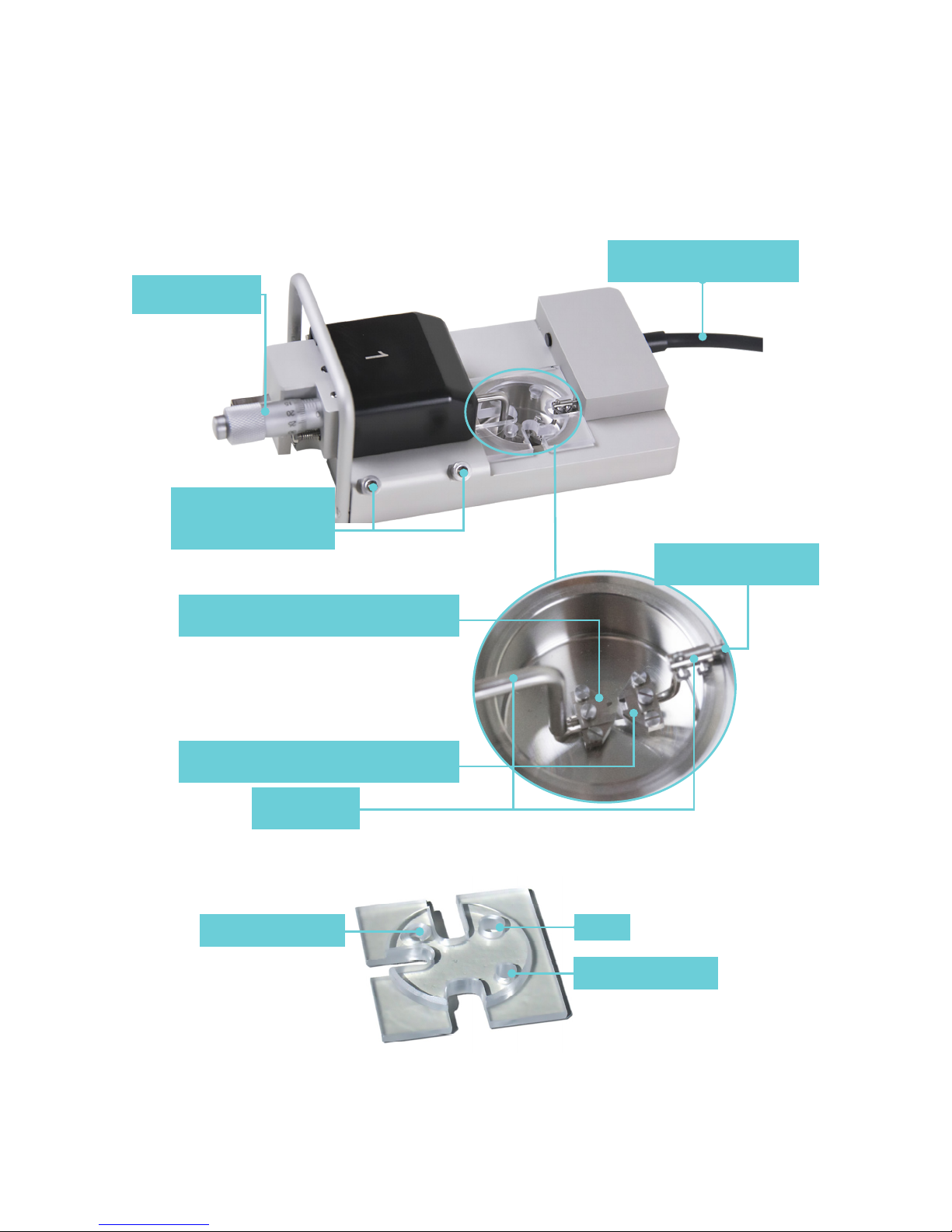
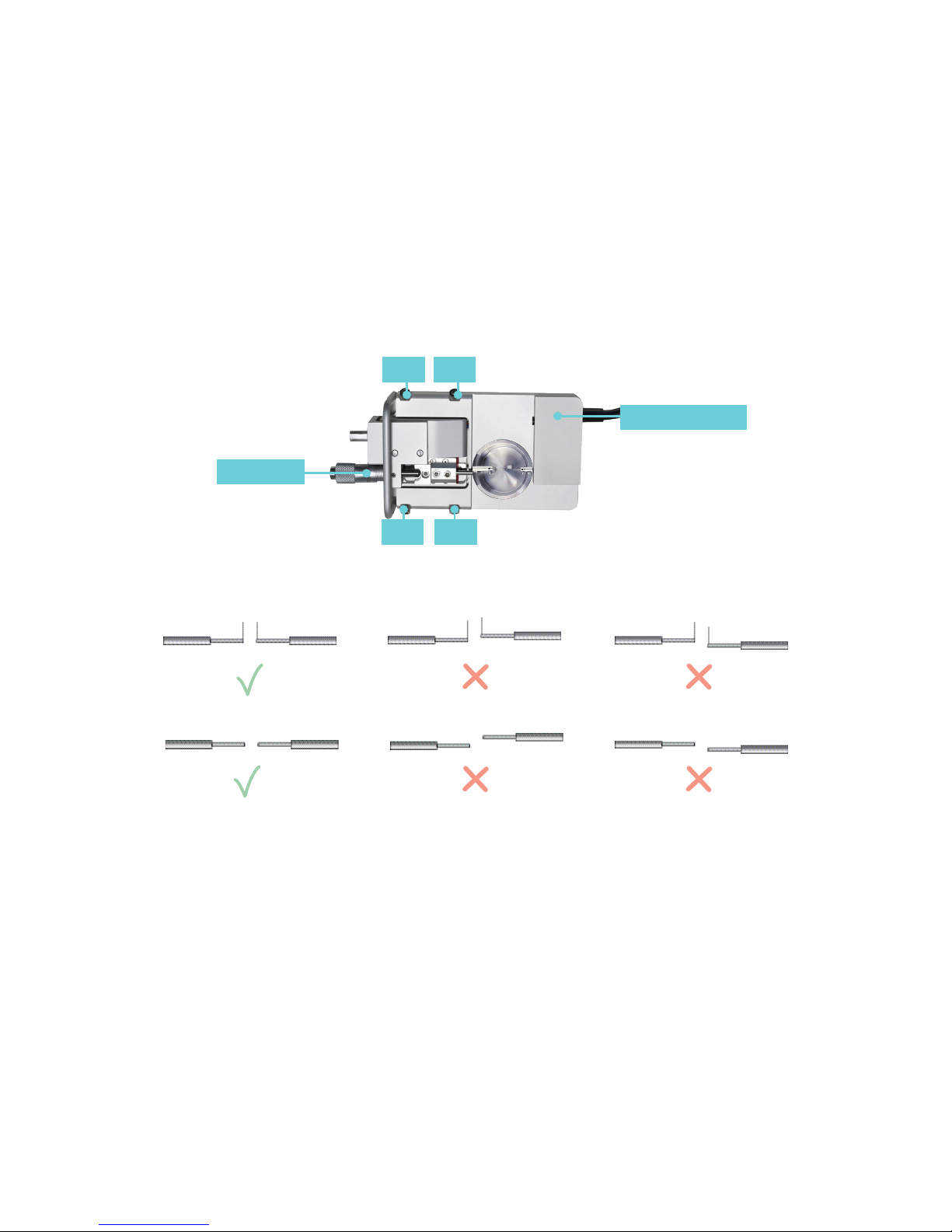
Each chamber can accommodate mounting
supports for either small vessels (>30µm) or
larger segments (>500µm). Because the mounting
supports can be changed easily, experiments can
be performed with dierent vessels of varying
internal diameter. Continuous use and repeated
greasing of the transducer pin holes will cause
some misalignment of the mounting supports.
The mounting supports, therefore, whether
they are the jaws for wires or the pins, will need
occasional adjustments.
Changing and adjustment of the supports is
performed using the following step-by-step
procedure.
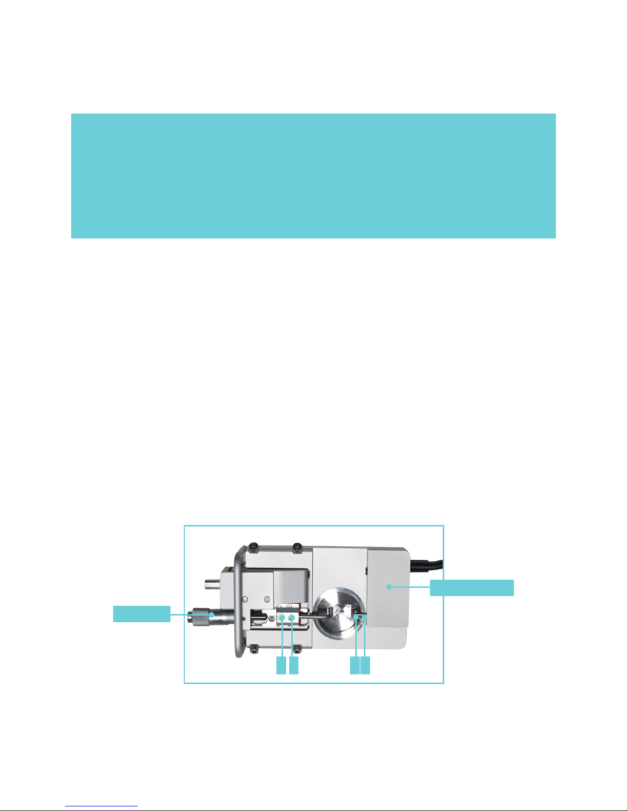
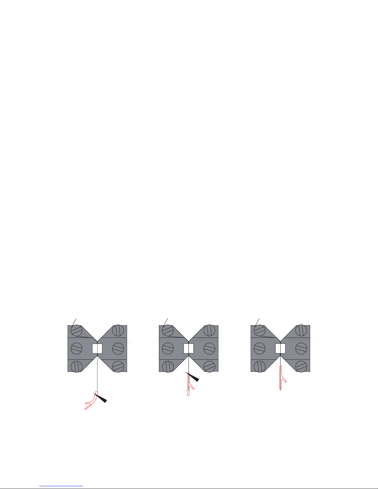
2.1.1 CHANGING THE MOUNTING SUPPORTS (FIGURE 2.1)
1. Use the micrometer to separate the supports
as far apart as possible.
2. Use the small screwdriver provided to gently
loosen screw D on the support attached on the
transducer side using the small screwdriver.
Screw D is the screw on the transducer-side
support closest to the transducer.
3. Gently pull the support away from the
transducer pin.
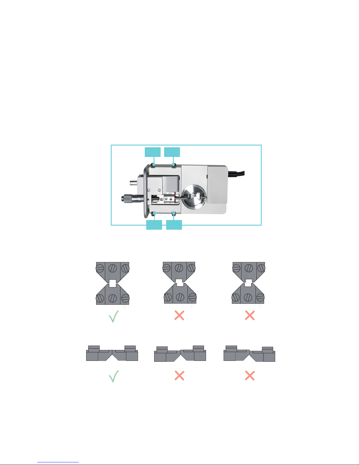
4. Loosen screw B on the micrometer side with
the appropriate tting allen key.
5. Pull the support away. Note: Number the
supports with the chamber number they
were removed from using some kind of
permanent marker. Store the supports in
the provided plastic case. Numbering the
supports will save time when the sup ports
are changed again, limiting the amount of
adjustments needed after each change.