DMX4ALL X9HR User manual

DMX-LED-DIMMER X9HR
User Manual

DMX-LED-Dimmer X9HR 2
For your own safety, please read this user manual and warnings carefully
before installation.
Contents
Description.................................................................................................................. 3
Data sheet .................................................................................................................. 4
Connection with one power supply ............................................................................. 5
Connection with several power supplies..................................................................... 6
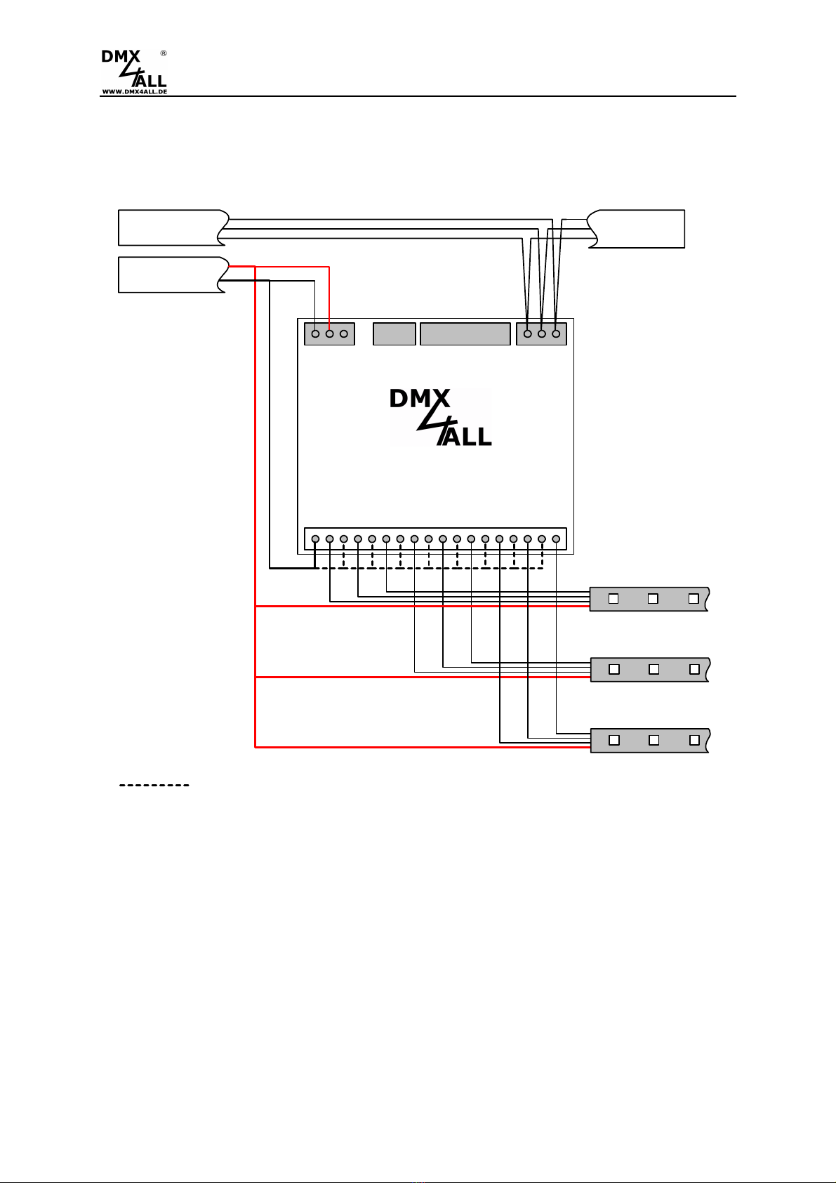
Connection with single color and multi color stripes ................................................... 7
Cable lengths.............................................................................................................. 8
DMX-Addressing ........................................................................................................ 9
LED-Display................................................................................................................ 9
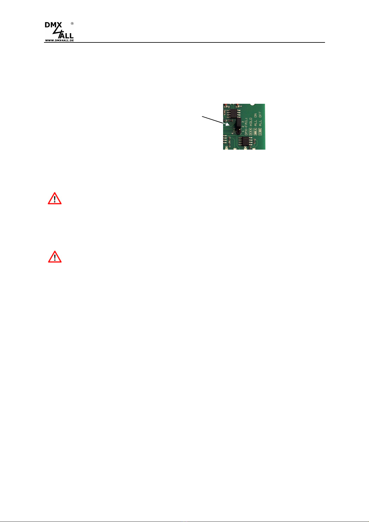
DMX FAIL action ...................................................................................................... 10
CTRL-Output (Energy-Save) .................................................................................... 11
Operation modes ...................................................................................................... 12
9Ch. Dimmer 8Bit with dimming curve .................................................................. 12
9Ch. Dimmer 16Bit................................................................................................ 12
9Ch. Dimmer 8Bit 2kHz (linear) ............................................................................ 13
9Ch. Dimmer 8Bit 4kHz (linear) ............................................................................ 13
Configuration of the dimming curve (Curve definition).............................................. 14
DMX-Master-Dimmer................................................................................................ 16
RDM ......................................................................................................................... 17
SubDevice-Mode ...................................................................................................... 21
Execute firmware Update ......................................................................................... 23
Factory Reset ........................................................................................................... 24
Equipment ................................................................................................................ 25
CE-Conformity .......................................................................................................... 26
Disposal.................................................................................................................... 26
Risk-Notes ................................................................................................................ 27

DMX-LED-Dimmer X9HR 3
Description
The DMX-LED-Dimmer X9HR is especially designed for controlling RGB LED-
Stripes. The dimmer has 9 High-Resolution PWM-Outputs (3xRGB) independently
controllable via DMX.
9 Outputs
The DMX-LED-Dimmer X9HR has 9 outputs to which LEDs can be connected. All
outputs are designed in the same way so single color, RGB or RGBW LEDs can be
connected.
High Power Outputs
The outputs can drive a current up to 10A.
So it is possible to connect a maximum load of 120W (12V) / 240W (24V).
0% to 100% dimmable
The connected LEDs are dimmed by PWM from 0% to 100%.
For voltages from 12V up to 24V
The DMX-LED-Dimmer X9HR operates with supply voltages from 12V up to 24V.
The LED voltage can be different per output so that one X9HR DMX-LED-Dimmer
can control different LED systems.
DMX-FAIL Function
An adjustable DMX FAIL function offers the option to get in case of lost DMX signal
the current state (HOLD) or assuming a preset value.
DMX-Master Dimmer
Optionally, another DMX channel can be activated as Master Dimmer (all outputs) or
one master dimmer per RGB group. The global master dimmer is fixed at DMX
address 1 and can be used as system master dimmer.
Adjustable dimming curve
The dimming curves can be configured individually for each output.
RDM support
The DMX-LED-Dimmer X9HR allows configuration by RDM via DMX.
SubDevice-Mode
In SubDevice mode, each output is assigned its own DMX address and DMX FAIL
behavior via RDM.
LED-State Display
The DMX state is indicated via the LED status.
Firmware-Update-Function
To use future functions, the DMX-LED-Dimmer X9HR offers a firmware update
function.
Top hat rail housing available
The top-hat rail housing 1050 is available as accessory for the DMX-LED-Dimmer
X9HR.

DMX-LED-Dimmer X9HR 4
Data sheet
Power supply: 7-24V DC
80mA@12V / 100mA@24V
(without connected LED load)
LED voltage: 7-24V DC
(no AC voltage !)
Protocol: DMX512
RDM
DMX channels: 9 channels with 8Bit-controlling and LookUp-Table
18 channels with 16Bit-controlling
+ optional Master-Dimmer-Channels
DMX-FAIL: Hold / 0%-100%
Output: 9 PWM-signal with 16Bit-resolution
Common supply voltage
Output current: max. 10A each output
In sum 90A with all GND connections
(direct from power
supply)
Output power: 9x 120W (12V) / 9x 240W (24V)
Masterdimmer: None / Global / RGB / System
PWM-frequency: 488 Hz / 2kHz / 4kHz
CTRL output: Control output for switching off the load power supply units
(Energy-Save)
StandAlone function: 9 internal StandAlone programs
Connections: Screw terminals
Dimensions: 99mm x 82 mm

DMX-LED-Dimmer X9HR 5
Connection with one power supply
DMX-LED-Dimmer X9HR
RGB-LED-Stripe (12V)
POWER 12V
GND
V+
GND
OUT1
GND
OUT2
GND
OUT3
GND
OUT4
GND
OUT5
GND
OUT6
RGB-LED-Stripe (12V)
V+
DMX+
DMX-
GND
ADDRESS
GND
GND
GND
OUT7
OUT8
OUT9
DMX IN
DMX OUT
CFG
Must be connected direct
from the power supply !
Use at least one GND
connection per 10A.

DMX-LED-Dimmer X9HR 6
Connection with several power supplies
DMX-LED-Dimmer X9HR
RGB-LED-Stripe (12V)
POWER 12V
GND
V+
GND
OUT1
GND
OUT2
GND
OUT3
GND
OUT4
GND
OUT5
GND
OUT6
RGB-LED-Stripe (24V)
RGB-LED-Stripe (12V)
V+
DMX+
DMX-
GND
ADDRESS
GND
GND
GND
OUT7
OUT8
OUT9
DMX IN
DMX OUT
POWER 12V
POWER 24V
POWER 12V
CFG
Must be connected direct
from the power supply !
Use at least one GND
connection per 10A.

DMX-LED-Dimmer X9HR 7
Connection with single color and multi color stripes
DMX-LED-Dimmer X9HR
RGB-LED-Stripe (12V)
POWER 12V
GND
V+
GND
OUT1
GND
OUT2
GND
OUT3
GND
OUT4
GND
OUT5
GND
OUT6
LED-Stripe WEIß (12V)
V+
DMX+
DMX-
GND
ADDRESS
GND
GND
GND
OUT7
OUT8
OUT9
DMX IN
DMX OUT
CFG
Must be connected direct
from the power supply !
Use at least one GND
connection per 10A.

DMX-LED-Dimmer X9HR 8
Cable lengths
The DMX-LED-Dimmer X9HR should be run with shortest possible cable lengths.
Because of the low operation voltage in LED installation the cable cross section is to
choose as large as possible to keep the voltage drop as low as possible on the cable.
The cable cross section should be all the larger as the distance increases and the
load increases.
The following cable lengths should not be exceeded:
From power supply to DMX-LED-Dimmer X9HR 1m
From DMX-LED-Dimmer X9HR to LEDs 10m

DMX-LED-Dimmer X9HR 9
DMX-Addressing
The starting address is adjustable with the switches 1 to up 9.
Switch 1 has the valency 2
0
(=1), switch 2 the valency 2
1
(=2) etc. until switch 9 has
the valency 2
8
(=256). In total the switches showing ON correlate with the starting
address.
LED-Display
The integrated LED is a multifunctional-display.
During the normal DMX-Operation the LED flashes permanent. In this case the
device is working.
Furthermore, the LED shows the event. In this case the LED lights in short pitches
and then turns into the off mode for a longer period. The number of flashing impulses
corresponds with the error status:
Error
Status
Error
Description
1 No DMX There is no DMX-Signal reaching the
dimmer
2 Address error Check if a valid DMX starting address is
adjusted at the DIP-switch
4 Factory Reset A Factory-Reset was executed
1
2
4
8
16
32
64
128
256
OFF

DMX-LED-Dimmer X9HR 10
DMX FAIL action
(from 06/2013 / Version 2)
The DMX-LED-Dimmer X9HR can hold the last value, switch on or switch off the LED
outputs on DMX fail.
This DMX-Fail option is selectable with the
Jumper.
HOLD: Hold last value
ALL ON: Turn on all outputs (100%)
ALL OFF: Turn off all outputs (0%)
After voltage drop the held values are not restored by the HOLD function.
In this case the values are set to 0 (OFF).
Via the RDM parameter DMX_FAIL_MODE the level can be adjusted
also.

DMX-LED-Dimmer X9HR 11
CTRL-Output (Energy-Save)
(from 06/2014 / Version 2.1)
The DMX-LED-Dimmer X9HR has an Energy-Save control output (CTRL) which is
able to run off the Load Power Supply of the LEDs.
If none of the outputs is activated for a period of 5 minutes or all DMX values are set
to 0 for 5 minutes, the control output is switched off.
So, the power loss for power supply units that are not needed for a longer period of
time can be avoided.
Example installation:
OUT9
GND
V+
GND
OUT1
GND
OUT2
GND
OUT3
GND
OUT4
GND
OUT5
GND
OUT6
CTRL
DMX+
DMX-
GND
GND
GND
GND
OUT7
OUT8
A1+
A1 -
1/L1
2/T1
L1
N
12V
GND
L1
N
Netzteil 12V
ower Solid
State Contactor
OUT-
OUT+

DMX-LED-Dimmer X9HR 12
Operation modes
The DMX-LED-Dimmer X9HR has several operating modes that can be set using
configuration switches 3 and 4:
- 9Ch. Dimmer 8Bit with dimming curve
- 9Ch. Dimmer 16Bit
- 9Ch. Dimmer 8Bit 2kHz (linear)
- 9Ch. Dimmer 8Bit 4kHz (linear)
The operating mode (configuration switches 3 and 4) can be combined with
the DMX master dimmer (configuration switches 1 and 2).
9Ch. Dimmer 8Bit with dimming curve
In this operating mode, each output is controlled with a DMX channel
(8Bit). A freely programmable dimming curve (look-up table / curve
definition) is available for each output, which maps the 8-bit DMX value to
the 16-bit resolution of the output. The output characteristics are
preprogrammed linear and can be freely programmed.
9Ch. Dimmer 16Bit
In this operating mode, each output is controlled with two DMX channels
(16Bit). There is a 16-bit resolution for each output, which is mapped
directly via the DMX values. 2 DMX channels are used per output. The
2nd DMX channel is the fine adjustment.
Configuration switches

DMX-LED-Dimmer X9HR 13
9Ch. Dimmer 8Bit 2kHz (linear)
(from FW V1.1)
In this operating mode, each output is controlled with a DMX channel
(8Bit). The output is controlled with 2kHz and a linear dimming curve.
9Ch. Dimmer 8Bit 4kHz (linear)
(from FW V1.1)
In this operating mode, each output is controlled with a DMX channel
(8Bit). The output is controlled with 4kHz and a linear dimming curve.
The high frequency output of 2kHz or 4kHz is optimized for use in connection
with video recording e.g. in TV studios.

DMX-LED-Dimmer X9HR 14
Configuration of the dimming curve (Curve definition)
The DMX-LED-Dimmer X9HR has a freely programmable dimming curve (look-up
table / curve definition) for each output.
The received DMX-Channel has values from 0 up to 255 (8 bit). The DMX-LED-
Dimmer X9HR output driver provides 65536 steps (16 Bit) which are assigned to the
DMX values.
So, it is possible to effect with small steps little brightness changings in the lower
brightness range. However, in the upper brightness range it’s possible to program
bigger steps.
If no dimming curve is configured (delivery status) the output control is linear.
Set dimming curve via RDM
The RDM parameter CURVE_DEFINITION is used to set the dimming curve /
lookup tables.
For this parameter, the Program RDM Configurator offers the following interface
for editing the dimming curve:
A detailed description of the functions can be found in the RDM Configurator
manual.

DMX-LED-Dimmer X9HR 15
Set dimming curve via USB
To transfer the Look-Up Table to the DMX-LED-Dimmer X9HR a PC-Connection
cable and a USB-Connection at the PC is necessary.
Via the software DMX-Configurator the LookUp-Tables can be defined. The DMX-
Configurator is available for free as download.
- Connect the DMX-LED-Dimmer X9HR with a
standard USB-Mini-B connection cable to PC. As
shown in the picture on the right site, plug the
cable on the USB-Connection of the DMX-LED-
Dimmer X9HR.
- Install the USB-Driver if it is not available.
- Start the DMX-Configurator Software
(V2.3.9 or higher is needed)
- Generate a connection to DMX-LED-Dimmer X9HR
- Open Hardware-Settings (menu HardwareHardware Settings)
For each output (OUT1-OUT9) a table with DMX-Values in the range of 0-
255 and the according output values (OUTPUT) is available.
A graphic presentation illustrates the output line.
- Configure the output curve
- Check the output curve by selecting the LookUp Test and move the slider.
The connected LED behaves according to the output line.
- Select WRITE TO DEVICE to transfer the table to the DMX-LED-Dimmer
X9HR.

DMX-LED-Dimmer X9HR 16
DMX-Master-Dimmer
The DMX-LED-Dimmer X9HR has several Master Dimmer. These will be activated
as follows:
Master Dimmer for all channels
The DMX channel which is adjusted as starting address will be used as master
dimmer for all 9 outputs. The DMX-addresses assignment is as follows:
Master Dimmer per RGBgroup
Per RGB-Group one master dimmer is used. The DMX addresses assignment is as
follows:
System-Master Dimmer for all channels
The value for the master dimmer corresponds with the DMX channel 1 used as
Master Dimmer for all 9 outputs. The DMX start address represents the DMX channel
on which the DMX values for the outputs begin. The DMX addresses assignment is
as follows:
Master
OUT 1 (R1)
OUT 2 (G1)
OUT 3 (B1)
OUT 4 (R2)
OUT 9 (B4)
Master
OUT 1 (R1)
OUT 1 (fine)
OUT 2 (G1)
OUT 2 (fine)
OUT 9 (B4)
OUT 9 (fine)
OUT 3 (B1)
OUT 3 (fine)
OUT 4 (R2)
OUT 4 (fine)
Master 1
OUT 1 (R1)
OUT 2 (G1)
OUT 3 (B1)
OUT 4 (R2)
OUT 9 (B4)
Master 1
OUT 1 (R1)
OUT 1 (fine)
OUT 2 (G1)
OUT 2 (fine)
OUT 9 (B4)
OUT 9 (fine)
OUT 3 (B1)
OUT 3 (fine)
OUT 4 (R2)
OUT 4 (fine)
Master 2
Master 2
Master
OUT 1 (R1)
OUT 2 (G1)
OUT 3 (B1)
OUT 4 (R2)
OUT 9 (B4)
Master
OUT 1 (R1)
OUT 1 (fine)
OUT 2 (G1)
OUT 2 (fine)
OUT 9 (B4)
OUT 9 (fine)
OUT 3 (B1)
OUT 3 (fine)
OUT 4 (R2)
OUT 4 (fine)
No Master Dimmer
Master Dimmer for all channels
Master Dimmer per RGB-group
System Master Dimmer for all channels
Startaddress Start address
Start address Startaddress
Start address Start address
Channel 1 Channel 1

DMX-LED-Dimmer X9HR 17
RDM
(from hardware V2.3)
RDM is the short form for Remote Device Management.
As soon as the device is within the system, device-dependent settings occur remotely
via RDM command due to the uniquely assigned UID. A direct access to the device is
not necessary.
If the DMX start address is set via RDM, all address switches at the DMX-
LED-Dimmer X9HR must be set to OFF ! A DMX start address set by the
address switches is always prior !
This device supports the following RDM commands:
Parameter ID
Discovery
Command
SET
Command
GET
Command
ANSI/
PID
DISC_UNIQUE_BRANCH
E1.20
DISC_MUTE
E1.20
DISC_UN_MUTE
E1.20
DEVICE_INFO
E1.20
SUPPORTED_PARAMETERS
E1.20
PARAMETER_DESCRIPTION
E1.20
SOFTWARE_VERSION_LABEL
E1.20
DMX_START_ADDRESS
E1.20
DEVICE_LABEL
E1.20
MANUFACTURER_LABEL
E1.20
DEVICE_MODEL_DESCRIPTION
E1.20
IDENTIFY_DEVICE
E1.20
FACTORY_DEFAULTS
E1.20
DMX_PERSONALITY
E1.20
DMX_PERSONALITY_DESCRIPTION
E1.20
DISPLAY_LEVEL
E1.20
DMX_FAIL_MODE
E1.37

DMX-LED-Dimmer X9HR 18
Parameter ID
Discovery
Command
SET
Command
GET
Command
ANSI/
PID
SERIAL_NUMBER
1)
PID:
0xD400
DISPLAY_AUTO_OFF
1)
PID:
0xD401
IDENTIFY_MODE
1)
PID:
0xD402
CURVE_DEFINITION
1)
PID:
0xD430
SOFT_DIMMING
1)
PID:
0xD431
SUBDEVICE_ENABLE
1)
PID:
0xFF0F
1) Manufacturer depending RDM control commands (MSC - Manufacturer Specific Type)
Manufacturer depending RDM control commands
:
SERIAL_NUMBER
PID: 0xD400
Outputs a text description (ASCII-Text) of the device serial number.
GET Send: PDL=0
Receive: PDL=33 (33 Byte ASCII-Text)
DISPLAY_AUTO_OFF
PID: 0xD401
Sets the time after which the display is switched off (DISPLAY_LEVEL = 0).
Valid values are: 0 - NO AUTO OFF
600 - 1 minute
1200 - 2 minutes
1800 - 3 minutes
2400 - 4 minutes
3000 - 5 minutes
3600 - 6 minutes
4200 - 7 minutes
4800 - 8 minutes
5400 - 9 minutes
GET Send: PDL=0
Receive: PDL=2 (1 Word)
SET Send: PDL=2 (1 Word)
Receive: PDL=0

DMX-LED-Dimmer X9HR 19
IDENTIFY_MODE
PID: 0xD402
Sets the mode that is executed with IDENTIFY_DEVICE.
GET Send: PDL=0
Receive: PDL=1 (1 Byte IDENTIFY_MODE_ID)
SET Send: PDL=1 (1 Byte IDENTIFY_MODE_ID)
Receive: PDL=0
IDENTIFY_MODE_ID
Funktion
0 FULL Identify
All outputs switch ON / OFF simultaneously
and the status LED flashes
1 LOUD Identify
The outputs switch ON / OFF one after the
other and the status LED flashes
2 QUIET Identify
The outputs do not switch, only the status
LED flashes
CURVE_DEFINITION
PID: 0xD430
Sets the devices LookUp tables.
SOFT_DIMMING
PID: 0xD431
Sets the soft dimming behavior of the device.
GET Send: PDL=0
Receive: PDL=1 (1 Byte SoftDimm parameter)
SET Send: PDL=1 (1 Byte SoftDimm parameter)
Receive: PDL=0
Parameter
Fun
c
tion
0 Soft-Dimm OFF
1-255 Soft-Dimm up to the given value

DMX-LED-Dimmer X9HR 20
SUBDEVICE_ENABLE
PID: 0xFF0F
Enable or disable the sub devices of the device.
GET Send: PDL=0
Receive: PDL=1 (1 Byte SUBDEVICE_ENABLE_STATE)
SET Send: PDL=1 (1 Byte SUBDEVICE_ENABLE_STATE)
Receive: PDL=0
SUBDEVICE_ENABLE_STATE
Funktion
0 SUB DEVICES DISABLED
1 SUB DEVICES ENABLED
This manual suits for next models
1
Table of contents
Other DMX4ALL Dimmer manuals
Popular Dimmer manuals by other brands

Lutron Electronics
Lutron Electronics Maestro Wireless MRF2-3PD Application note

Aeon Labs
Aeon Labs Aeotec Nano Dimmer user guide

LiteGear
LiteGear LiteDimmer Pro Single user guide

Leviton
Leviton DDS8800 Installation and operation guide

Conrad
Conrad 640465 operating instructions

DALCNET
DALCNET SLIM 2CV CASAMBI Device manual