DNR Sunset User manual

Sunset User’s Manual
1
USER’S MANUAL
This manual MUST be given to the user of the product.
BEFORE using this product, read this manual and savefor future
reference.
Powered Wheelchair - Sunset

Sunset User’s Manual
2
1
2
8
3 9
10
11
4 12
5 13
14
15
6 16
7
1. Handle
2. Seat upholstery
3. Controller
4. Footrest
5. Footrest Shaft lock
6. Footplate
7. Front wheel
8. Foldable set
9. Armrest pad
10.Motors
11.Hand-rims
12.Hand Brake
13.Battery
14.Rear wheel mechanism
15.Anti-Tipper
16.Cross Bar
1. Assembly
Your power wheelchair is shipped partially disassembled to protect during shipping.
Please follow the below steps to assemble your power wheelchair.
1.1 Foldable Set Fig. 4
The foldable set is beneficial to reduce the overall height of the
power wheelchair.
1.1.1 Install the power wheelchair: Pull the handle forward till it
locks into the position. You will hear a click sound when the
handle is securely locked.
Please apply to both sides of foldableset.
1.1.2 Store the power wheelchair:
Grasp the handle with one hand and press the back support with theother hand. Push
the foldable set backward and pull the handle forward. Please see Fig. 4.
Please apply to both sides of foldable set.

Sunset User’s Manual
2
1.2 Installing The Power Wheelchair
1.2.1 Before use, unfasten the power wheelchair. Please hold the handle and lightly
expand the back support to the left and right. Please see Fig. 5.
1.2.2 Push down on one side of the seat frame, so your weight is applied from above
with both hands. Please see Fig. 6.
1.2.3 Make sure the seat frame securely fits into the seat. Please see Fig. 7.
1.2.4 Place the upholstery on the power wheelchair and the cushion on the seat. The
Velcro side is facing back/down.
Fig. 5
Fig. 6
Fig. 7
Warning: the power wheelchair has to be open completed and it
could cause the serious injury.
1.3 Storing The Power Wheelchair
1.3.1 Remove the upholstery and cushion.
1.3.2 Fold and store the footplate. Please see Fig. 8.
If necessary, remove the foot support. Please see Fig. 21 .
1.3.3 Lift the front and rear center of the seat. Please see Fig. 9.
1.3.4 Hold the handle and compress it from the left andright . Please see Fig. 10.
Fig. 8
Fig. 9
Fig. 10
3

Sunset User’s Manual
2
1.4 Installing Controller and Connecting Cables
1.4.1 Assemble the controller connect rod on the right armrest bracket.
Please fix the knob to fasten the controller. Please see Fig. 11 and Fig. 12.
1.4.2 Switch the controller rod to Leftarmrest
roller connect rod
Remove the screws that connect the controller connect rod and the controller.
Please see Fig. 13. Loose the fixed knob and controllerconnecting rod. Please see Fig.
14.
Fig. 13
Fig. 14
Remove the three screws on top of connecting rod. Turn the connecting rod over,
and the pin will be other side. Tighten three screws again. Please see Fig. 15 and
Fig. 16.
Warning: please be aware that the pinch may occur when
assemble and store the power wheelchair.
Fig. 11
Fig. 12
Fixed knob Bracket connect rod
Fixed knob Cont
Fixed knob
Remove the fixed knob
and connect rod.
4

Sunset User’s Manual
2
Fig. 15
Fig. 16
Reattach the controller connecting rod to theleft armrest. Please see Fig. 17.
Replace the controller and tighten the screws on theconnecting rod.. Please see Fig.
18.
Fig. 17
Fig. 18
1.5 Connecting The Cable
There is one plug in the other end of the controller. Please connect the plug with the
motor plug and make sure they aretightly connected. Please see Fig. 19 and Fig. 20.
Fig. 19
Fig. 20
Seal “LEFT” cable connects to the LEFT
Motor cable
Seal “RIGHT” cable connects to the
RIGHT Motor cable.
5

Sunset User’s Manual
2
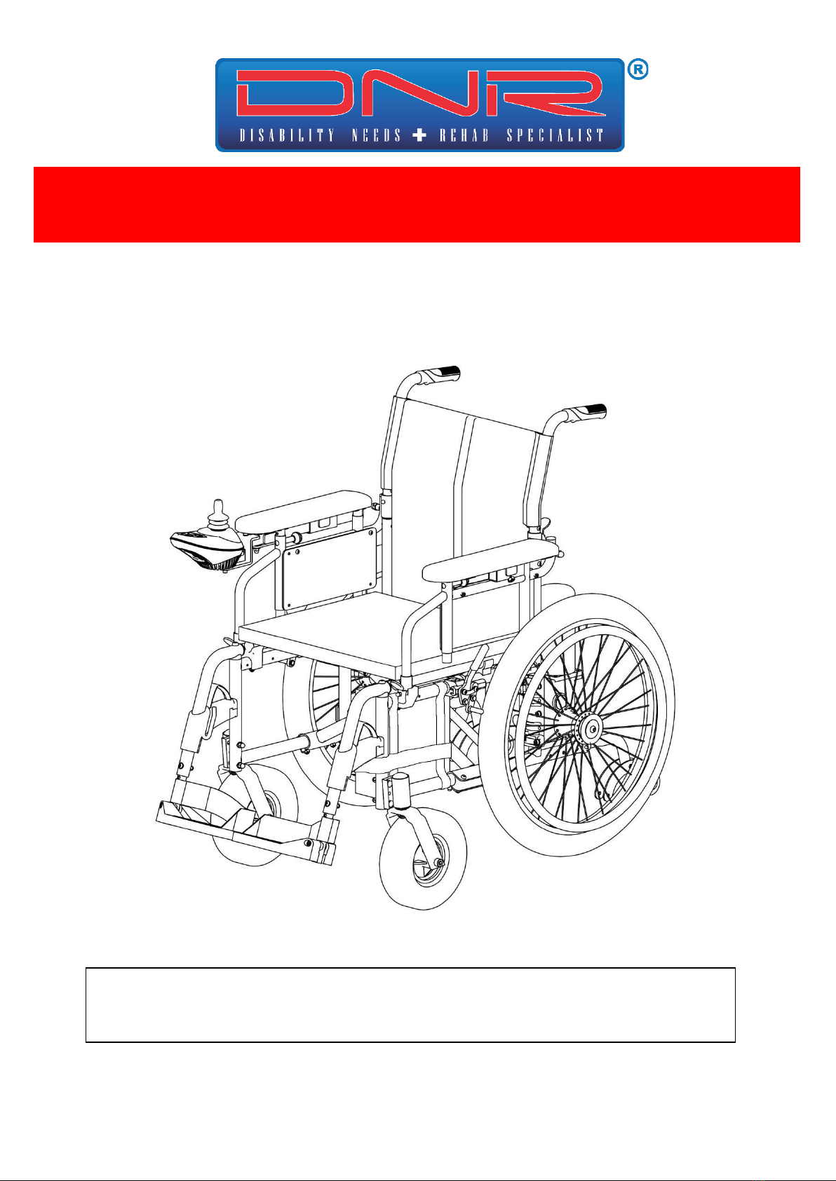
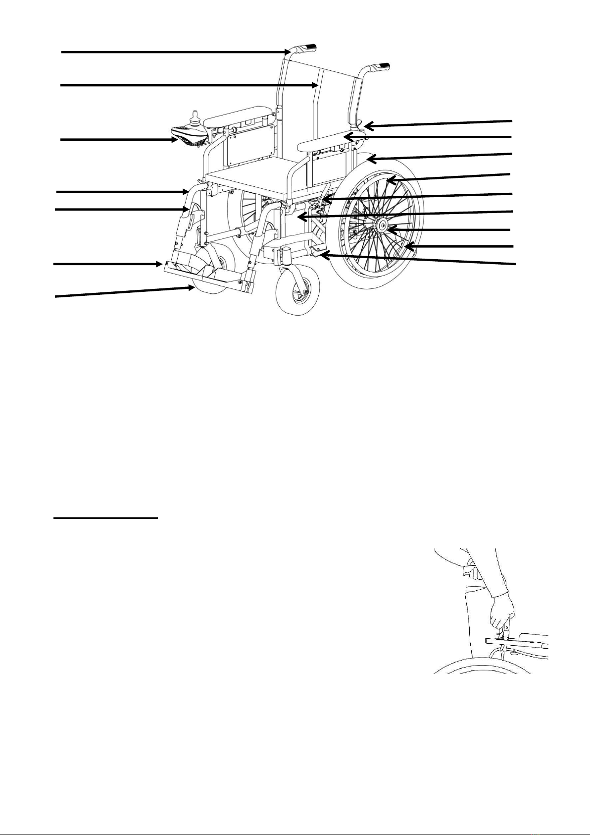
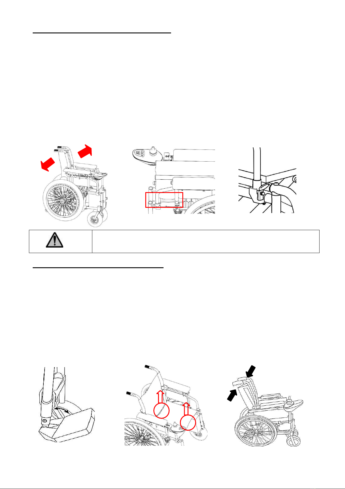
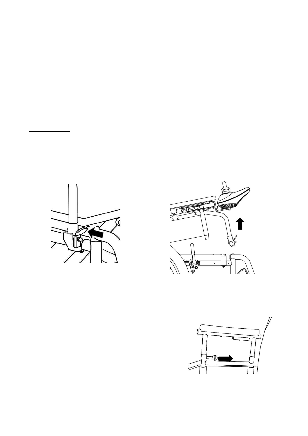
1.6 Installing and Removing Footrest
The footrest is swinging away and detachable.
When the footrest lock lever is raised, the footrest can be removed or turn around 90
degrees to correct direction. Please see Fig. 21.
2.1 Generals
2. Operation
2.1 1 Always turn off the power wheelchair.
2.1.2 Always be aware of the environment that surrounds you to select the desired speed.
2.1.3 For indoor environment, we recommend that you select the slowest speedsetting.
2.1.4 For outdoor environment, we recommend that you start at the slowest speed and
adjust to the speed that is comfortable for you to control it safely.
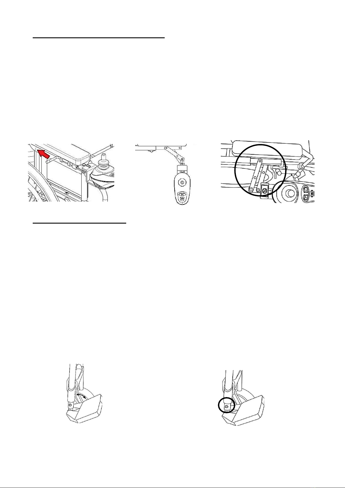
2.2 Manual Mode and Power Mode
2.2.1 Manual mode: the latch mechanism has a gap from the central plane.
Central plane Latch mechanism- Internal latch mechanism
(Fluorescence water transfer print)
Warning! Never try to use your power wheelchair beyondits
limitation as described in this manual.
6

Sunset User’s Manual
2
2.2.2 Power Mode: the latch mechanism is flush with the central plane.
Central plane Latch mechanism- Internal latch mechanism
(Fluorescence water transfer print)
2.2.3 Switch from Power Mode to Manual Mode
2.2.3.1 Pull out the latch mechanism and slightly turn it.
2.2.3.2 Then, release the latch mechanism and turn it till hear "click"sound.
2.2.3.3 You will see the height difference between the latch mechanism and the central
plane.
2.2.3.4 The power wheelchair is in manual mode.
2.2.4 Switch from Manual Mode to Power Mode
There is the height difference
between the central plane andthe
latch mechanism.
The latch mechanism is
flush as the central plane.
7

Sunset User’s Manual
2
2.2.4.1 Pull out the latch mechanism and slightly turn it.
2.2.4.2 Then, release the latch mechanism and turn it till hear "click" sound.
2.2.4.3 Make sure the latch mechanism is flush as the central plane.
2.2.4.4 If it is flush, the power wheelchair is in power mode.
2.2.4.5 If there is the height difference, please push the power wheelchair and make the
wheels turn till you hear "click" sound.
2.2.4.6 Recheck the latch mechanism is flush as the central plane. If so, it is in power
mode.
2.3 Armrest
2.3.1 Flip-up: when the released pad is pressed down, the armrest can be detached and
flip-up
Please See Fig. 22, and Fig. 23.
Fig. 22
Fig. 23
2.3.2 Armrest Height adjustment
Depending on the power wheelchair you are using, you can adjust the height of the
armrest in 5 different heights.
Pull the knob in the directness of the arrow and unlock it. It will release the armrest for
height adjustment. Please see Fig. 24. Return the knob, make sure it is locked.
It applies in both right and left side armrests.
Fig. 24
8

Sunset User’s Manual
2
2.4 Controller Retract Horizontally
The controller is mounted with a mechanism which allows the controller to be locked in
a forward or retracted position.
When the controller pin is pulled out, the controller connects rod can be retracted
horizontally. Please see Fig. 25, Fig. 26, and Fig. 27.
To return to forward position, pull to release the magnetic catch and swing to forward
position.
Fig. 25
Fig. 26
Fig. 27
2.5 Footrest Adjustment
2.5.1 Footplate Flip up
For moving in and out power wheelchair, please flip up the footplate.
Please see Fig. 28.
2.5.2 Footplate Height Adjustment
The height of the footrest can be adjusted according to the user’s need.
Please remove the bolt (shown in Fig. 29) and move the footplate to desired height. Re-
install bolt through the desired hole and tighten the bolt.
Fig. 28
Fig. 29
9

Sunset User’s Manual
2
2.6 Anti-Tipper Adjustment
2.6.1 Disengaging the anti-tipper
Removing the C type lock that locks the anti-tipper tothe frame. Pull the anti-tipper
out. Please see Fig. 30 and Fig. 31.
Fig. 30
Fig. 31
2.6.2 Anti-tipper adjustment
The C type lock must be removed first. Adjust the mounting hole position on both
sides of power wheelchair frame. Install the C type lock and make sure it is locked.
Please see Fig. 32 and Fig. 33.
Fig. 32
Fig. 33
2.7 Battery Replacement
2.7.1 Battery installation
Please follow the battery bag with battery direction as Fig. 34 shown.
Warning! Even the anti-tipper is in the correct position, thereis
a possibility of falling if the road surface is a cavity.
Warning! Operating the power wheelchair withoutanti-tippers
could result in death, serious injury or damage.
10

Sunset User’s Manual
2
Place the battery bag with battery on the front and left of power wheelchair main
frame.
There are two vertical Velcro passes over the power wheelchair main frame and battery
bag. Please paste with Velcro firmly. Please see Fig. 35.
Take the horizontal direction Velcro strap and cross over the power wheelchair main
frame. Please paste with Velcro firmly. Please see Fig. 36.
Fig. 34
Fig. 35
Fig. 36
2.7.2 Remove the battery
Please reverse the battery installation processes.
2.8 Hand Brake
Always use hand brake while in manual mode.
The hand brake is pushed to lock, pull to release. Fig. 37
3. Controller
For indoor environment, we recommend that you select the slowest speed setting.
For outdoor environment, we recommend that you start at the slowest speed and adjust
to the speed that is comfortable for you to control it safely.
3.1 Controller Panel
The Controller Panel is a multifunction visual display. It can provide the information:
Warning! Do not connect the battery cable and controller cable
with wet hands.
11

Sunset User’s Manual
2
Battery Gauge
ON/OFF button
Horn Button
Speed Profiles Indicator
Speed Button: Acceleration and Deceleration
Joy Stick
3.1.1 ON/OFF button
Press the ON/OFF button locates in front of the joystick to activate your power
wheelchair.
The controller’s LED light is on, the power wheelchair power is on.
If the controller’s LED light is off, the power wheelchair power is off.
3.1.2 Horn button
Activates a warning horn.
3.1.3 Battery Gauge
The battery Gauge is composed of 5 segments (1 of Red, 2 of Yellow,and 2 of Green).
The segments indicate the approximate amount of batterycapacity left. It enables you
to monitor the battery capacity status.
Battery Capacity(%)
Lights Display
60~100%
●●●●● 5 Lights
Red/Yellow/Yellow/Green/Green
40~60%
●●●●○ 4 Lights
Red/Yellow/Yellow/Green
20~40%
●●●○○ 3 Lights
Red/Yellow/Yellow
10~20%
●●○○○ 2 Lights
Red/Yellow
Below 10%
●○○○○ 1 Light
Red
Red/Yellow/Green lights lit: Batteries charged.
Red/Yellow lights lit: charge batteries if possible.
Red light only lit or slow flash: charge batteries as soon as possible.
When the battery is approaching a discharged state, the first red light will begin to
slowly flash, reminding you the batteries need to be charged immediately.
3.1.4 Speed Profiles Indicator (Acceleration/Deceleration Buttons)
The speed profiles indicator has 5 segments which indicate the maximum speed setting
selected.
12

Sunset User’s Manual
2
Pressing the speed, acceleration button will set the speed at the faster setting.
Pressing the speed deceleration button will slow down the speed.
The controller sets the reverse speed, acceleration and deceleration proportionally and
automatically for your safety.
3.1.5 Joystick
The joystick controls the direction, speed of your power wheelchair. Push the joystick
in the direction you want to go.
Pointing the joystick away from the center position will move the power wheelchair in
the direction where the joystick is pointing.
The forward of the joystick point from the center position, the faster the vehicle will go.
Returning the joystick to its center position will reduce the speed and stop the vehicle
by automatically applying the electromagnetic brakes.
The right or left the joystick is pointing, the power wheelchair will turn the direction
sharply.
After pressing the ON/OFF buttons, allow two seconds to elapse before engaging the
joystick. This is a safety feature to prevent sudden starts.
Gentle operation of the joystick will result in smoother transitions in speed and
direction, while sharp operation of the joystick will result in drastic transitions in
direction and velocity.
3.2 Manual Mode
The motors are designed to engage the electromagnetic brakes when the power
wheelchair is not in use or when the power is OFF. It has a feature to allow the power
wheelchair in manual mode.
Manual mode: the latch mechanism has a gap from the central plane.
Central plane Latch mechanism- Internal latch mechanism
(Fluorescence water transfer print)
13

Sunset User’s Manual
2
3.3 Electromagnetic Brakes
Your power wheelchair comes with an Electromagnetic Brakes., i.e. an automatic
magnetic disc safety brake which is also known as Fail-Safe brake.
The Electromagnetic Brakes are automatic and work when the power wheelchairs is ON
but in a steady state (i.e. Joystick is released to the center position), even when the
power wheelchair is on a slope. The Electromagnetic Brakes will also be set whenever
the power wheelchair is OFF, but the motor release levers are in the engaged (vertical)
position.
3.4 Thermal Protection
Your power wheelchair controller is equipped with a safety system called thermal
rollback. A built-in circuit monitors the temperature of the controller and motors, the
controller reduces the motor voltage and the speed of the power wheelchair. The
reduction of the speed allows the electrical components to cool down. Although your
power wheelchair will resume its normal speed when the temperature returns to a safe
level, we recommend that you turn the power off and wait for 30 seconds before
restarting to allow the components to cool down if you find that you have lost speed
suddenly.
4. Battery and Charger
4.1 Charger
The charger is an AC to DC switching-circuit designed Li-ion used charger. Best apply to
24V Li-ion battery. Pre-charge, constant current and constant voltage charging mode
designed with this charger.
Warning! Do not operate your power wheelchair in manual
mode on a slope.
14

Sunset User’s Manual
2
Fig. 38
Fig. 39
②①③⑤④
No
Item
Specification
①
Power cord
②
Ventilation hole
③
Cooling Fan
④
Power Cord
Lit Red: power is on.
⑤
Charging light
POWER /ON :RED ON
CHARGING : ORANGE ON
FULL CHARGE : GREEN ON
ERROR : RED LED FLASH
INPUT AC VOLTAGE
AC 100~240V 50/60HZ
OUTPUT DC VOLTAGE
24V
OUTPUT CURRENT
4A~6A
OPERATING TEMPERATURE
0℃~40℃
OPERATING HUMIDITY
20%~85% RH
STORAGE TEMPERATURE
-20℃~70℃
USED BELOW THE ALTITUDE
2000M
DIMENSIONS
L183mm*W 100mm*H 58mm
WEIGHT
0.81KG
4.2 Charging Instruction
4.2.1 General
For maximum performance, it is recommended that recharge the Li-ion battery
periodically or every time after you finish using the power wheelchair to prevent battery
damage.
If the power failure occurs accidentally, please wait for 30 seconds and turn on the
power again for operation.
The charger is intended for indoor use only. Protect from moisture.
If the power wheelchair will not be used for a long period of time, arrange to have the
15

Sunset User’s Manual
2
Charger’s charger
batteries fully charge for at least once every month.
According to the battery type and condition of the battery, the battery usually can be
fully charged in 3 to 6 hours. This will be indicated when the status LED light in the
battery charger side panel turn green.
Charging the battery longer than necessary will not harm the battery. We
recommended that you charge the battery for 4 to 6 hours afterdaily use. Do not
charge the battery for more than 24 hours.
4.2.2 There are two ways to recharge your power wheelchair:
-Charge the battery while it is attached to the power wheelchair. Please see Fig. 41.
-Charge the battery after removes it from the power wheelchair. Please see Fig. 42.
Fig. 40
Fig. 41
Fig. 42
4.2.3 Charge the battery while it is attached to the power wheelchair
4.2.3.1 Turn off the power of the power wheelchair.
4.2.3.2 Place the power wheelchair on a flat place in the room and apply the hand
brake.
4.2.3.3 Place the power wheelchair close to a standard electrical wall outlet.
4.2.3.4 Remove anything that may be caught on the charging cable before use.
4.2.3.5 Plug the charger power cord (Round head) into to the controller.
4.2.3.6 Plug the charger power cord into a standard electrical wall outlet. A Red
and a Yellow (if the battery charge is low), LED will illuminate.
4.2.3.7 The LED (orange) light will turn on when the battery is incharging.
4.2.3.8 When the battery is fully charged, the LED light turns to Green light.
4.2.3.9 Disconnect the charger power cord from the wall outlet when the batteries are
fully charged.
If the unplug DC connector during charging before LED shows green light, the LED will
16

Sunset User’s Manual
2
flash red light. If meet this situation, please unplug AC cord over 10 seconds till the
light off and then plug AC cord in again.
4.2.4 Charge the battery after removes it from the power wheelchair.
Please remove the battery from the power wheelchair, and apply the step above.
4.2.5 Charger Trouble Shooting
4.2.5.1 Power LED (red) is not on.
Check whether plug socket (AC) has normal output; if yes, and the indicator does
not shine, please return charger to supplier.
4.2.5.2 Charging LED (orange) light in not on.
4.2.5.2.1 Check whether output connector of charger is correctly connected with
battery set.
4.2.5.2.2 Check whether battery is full-charged.
4.2.5.2.3 If mentioned above are correct charger is likely to be defective. Please
return it to charger supplier for check up.
4.2.5.3 Charging LED (orange) light can not turn to green.
Battery is likely to be defective and can’t charge normally. Please return battery set to
battery supplier.
4.2.5.4 Charging LED (orange) light turn to green immediately.
Make sure the battery is fully charged. If not, battery is likely to be defective. Please
return battery set to battery supplier.
5. Care Maintenance
5.1 Periodic Checks
5.1.1 Daily Check
5.1.1.1 With the controller turned OFF, perform a joystick check. Make sure it is not bent
or damaged and that it returns to center when you release it. Visually inspect the rubber
boot around the base of the joystick for damage. Do not handle or try to repair it.
5.1.1.2 Visually inspect the controller harnesses. Make sure that they are not frayed, cut
or have any exposed wires.
5.1.1.3 Inspect the battery condition meter on the controller to determine if the batteries
need to be charged.
17

Sunset User’s Manual
2
5.1.2 Weekly Check
5.1.2.1 Inspect the connections by disconnecting the controller and charger harnesses
from the electronics connector housing. Look for signs ofcorrosion.
5.1.2.2 Ensure that all parts of the controller system are securely fastened to your power
wheelchair. Do not over tighten any screws.
5.1.2.3 Check the brakes. This test should be carried out on a level surface with at least
three feet of clearance around your power wheelchair.
5.1.2.4 Tocheck the brakes (your power wheelchair may move slightly when performing
this test)
5.1.2.4.1 Turn on the controller and turn down the speed and response adjustment
knob.
5.1.2.4.2 After one second, check that the battery condition meter remains on
condition.
5.1.2.4.3 Slowly push the joystick forward until you hear the parking brakes click then
immediately release the joystick. You must be able to hear each parking brake operate
within a few seconds of joystick release.
5.1.2.4.4 Repeat this test of the brake in the back, left and right joystick positions
5.1.3 Periodic Check
5.1.3.1 Always to keep controllers clean, avoid its contact with water or rain. Do not rinse
using water pipes or in direct contact withwater.
5.1.3.2 Please avoid tire contact on the flannel, hair, sand and carpet fibers.
5.1.3.3 If the Tread pattern of the tire is not deep enough, please change the tire.
5.1.3.4 The upholstery can be separate cleaned, soaking, make it into the laundry bag,
and then you can clean it by washing machine.
5.1.3.5 Also check upholstery whether is subsidence, cut or tear, you can replace it if it's
necessary.
18
Table of contents
Other DNR Wheelchair manuals