manuals.online logo
Brands
  1. Home
  2. •
  3. Brands
  4. •
  5. Dodge
  6. •
  7. Industrial Equipment
  8. •
  9. Dodge ISNX User manual

Dodge ISNX User manual

1
WARNING: Because of the possible danger to person(s)
or property from accidents which may result from the
improper use of products, it is important that correct
procedures be followed. Products must be used in
accordance with the engineering information specified
in the catalog. Proper installation, maintenance and
operation procedures must be observed. The instructions
in the instruction manuals must be followed. Inspections
should be made as necessary to assure safe operation
under prevailing conditions. Proper guards and other
suitable safety devices or procedures as may be
desirable or as may be specified in safety codes should
be provided, and are neither provided by Dodge nor are
the responsibility of Dodge. This unit and its associated
equipment must be installed, adjusted and maintained by
qualified personnel who are familiar with the construction
and operation of all equipment in the system and the
potential hazards involved. When risk to persons or
property may be involved, a holding device must be an
integral part of the driven equipment beyond the speed
reducer output shaft.
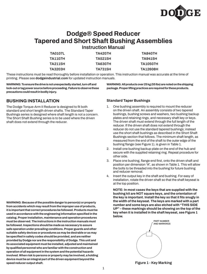
WARNING: To ensure the drive is not unexpectedly
started, turn off and lock-out or tag power source before
proceeding. Failure to observe these precautions could
result in bodily injury.
WARNING: All products over 25 kg (55 lbs) are noted on the
shipping package. Proper lifting practices are required for
these products.
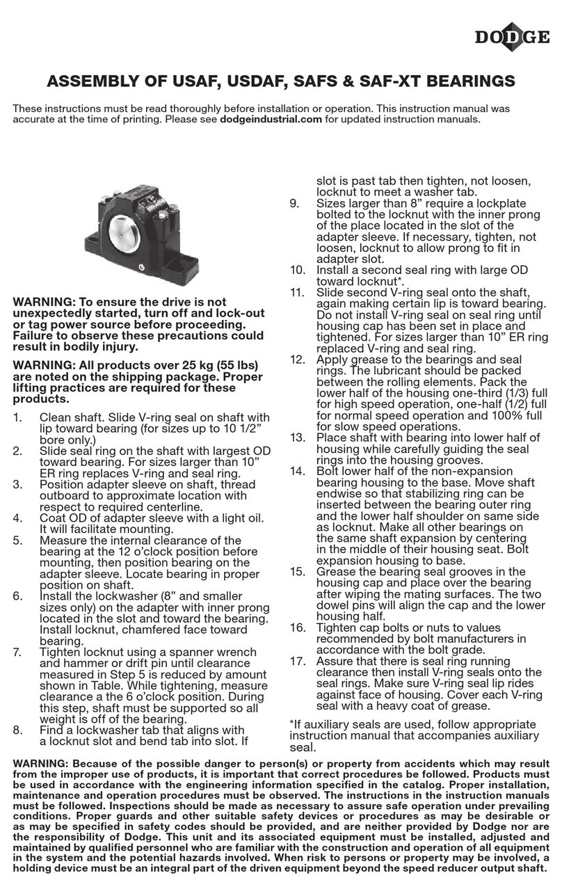
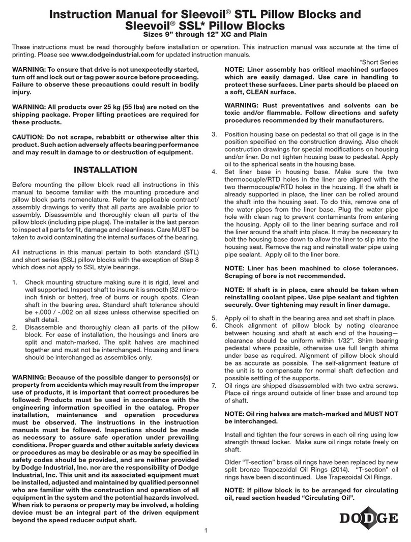
ISNX Bearings Hydraulic Mount Patent # 7,866,894
Instruction and Lubrication Manual
These instructions must be read thoroughly before installation or operation. This instruction manual was accurate at the time of
printing. Please see dodgeindustrial.com for updated instruction manuals.
INSPECTION
Inspect shaft to ensure it is smooth, straight, clean and within
commercial tolerances. All weight must be removed from the
shaft prior to installing.
TOOLS REQUIRED FOR PROPER
INSTALLATION AND REMOVAL
• Hydraulic Hand Pump, Hose and Fluid
• G1/4 - 19 BSPP Fitting
• 0-350 bar Pressure Gauge for Hydraulic Pump
• M6 Allen Wrench
• Magnetic Base Dial Indicator
• Torque Wrench with Appropriate Socket (See Table 3)
• Drift and Hammer
• Rubber Mallet
• Hand File
• Adjustable Wrench
• 13 mm diameter Barring Rods (2), approximately 200
mm in length
MOUNTING PROCEDURE
NOTE: Misalignment must be within ± 1/2º.
Install Non-Expansion (Fixed) Bearing First
1. Remove lubricatable auxiliary seals from OD of Mount and
Dismount Nuts. Be careful not to damage the two O-rings
in bore of seal. Note orientation of seal.
2. Remove lock clip located on the face of Mount Nut.
NOTE: The face of the Mount Nut equally spaced drilled
and tapped holes and an instruction plate. The Dismount
Nut contains three sets of drilled and tapped holes located
120° apart.
1/4 NPTF 1/4 NPTF
Mount Nut Dismount Nut
Figure 1 - Mount Nut and Dismount Nut
3. Scribe a line on Adapter face and Dismount Nut.
4. Rotate Dismount Nut counter clockwise two full rotations.
The Dismount Nut must remain loose during the mounting
procedure but should never be removed. Without loosening
the dismount nut, the dismount nut piston will make
contact with the bearing unit as it travels up the adapter.
(See Figure 3) This will not allow the bearing to move up the
adapter and tighten properly.
5. Rotate Mount Nut counter clockwise one full rotation and
tap on the face with a rubber mallet. This will drive the
adapter toward the Dismount Nut end and ensures the
Adapter is fully expanded.
6. Slide one lubricatable auxiliary seal on shaft in same
orientation as when it was removed.
7. Slide bearing on shaft and into position. If bearing will not
slide onto the shaft repeat Step 5.
8. Using a spanner or barring rod rotate Mount Nut clockwise
until snug. This allows the mount nut piston to be in full
contact with the bearing unit so that when the mount nut
is pressurized with hydraulic uid, the piston will push the
bearing unit up the adapter and properly tighten.
2
Table 1 - Starting Position Pressure
Bearing
Series Bore
Starting
Position
Final
Position
Recommended Shaft
Tolerances
(bar) (mm) (mm)
23134 150 mm 12.0 0.914 +.00
-.13
23136 160 mm 13.0 0.965
+.00
-.15
23138 170 mm 13.6 1.041
23140 180 mm 16.6 1.092
23144 200 mm 16.1 1.194
23148 220 mm 25.8 1.270 +.00
-.18
23152 240 mm 29.5 1.372
23156 260 mm 2 7.7 1.473
+.00
-.20
23160 280 mm 23.8 1.575
23164 300 mm 27.0 1.676
23168 320 mm 30.1 1.803
23172 340 mm 30.0 1.905
23176 360 mm 28.0 1.981
9. Attach a hydraulic pump to either of the two G1/4 - 19
BSPP Fitting hydraulic ports found on the Mount Nut. They
contain pipe plugs and are located on the face and OD of
the nut 180° apart.
10. Actuate hydraulic pump until Starting Position Pressure
(Table 1) is attained.
11. Install a magnetic base indicator or displacement gauge.
• Displacement Gauge: Install gauge in hydraulic port on
face of Mount Nut. Follow instructions included with
gauge for proper installation.
• Magnetic Base Indicator: Place on the shaft with the
anvil on face of inner unit as shown in Figure 2.
12. Zero the Indicator.
13. Actuate hydraulic pump until indicator indicates movement
as shown in the nal position column of Table 1.
Periodically check the dismount nut to ensure that it is still
loose during the mounting process.
NOTE: If hydraulic pressure reaches 345 bar prior to
attaining Final Position, abort procedure by releasing
pressure to hydraulic nut. Check to ensure Dismount
Nut is still loose. If not, rotate it counter clockwise 1
full rotation and repeat Step 13.
14. Remove Indicator from shaft or displacement gauge from
mount nut.
15. Release pressure to hydraulic pump and rotate Mount
Nut clockwise until snug. This forces the hydraulic
fluid back into the pump. Failure to complete this step
may result in the locknut loosening during operation
after it is tightened.
16. Remove hydraulic attachment from Mount Nut and insert
supplied pipe plug.
17. Using a spanner or drift and hammer, drive the Mount Nut
clockwise until the lock clip can be inserted into one of the
adapter slots and aligned with the drilled and tapped lock
clip holes.
NOTE: Always tighten, never loosen, the Mount Nut.
18. Insert lock clip and tighten lock clip bolts.
19. Using a barring rod, rotate Dismount Nut clockwise until
snug.
20. Align one of the set screws with the slot in the adapter.
Rotate the dismount nut COUNTER CLOCKWISE if
necessary until a set screw engages the slot.
21. Tighten that set screw to 135 Nm (99 ft-lbs.)
22. Place the stabilizing ring over Mount Nut.
23. Install the lubricatable auxiliary seals onto the Mount and
Dismount Nuts. Ensure all burrs or sharp edges are led off
the shaft, so that the o-rings in the seals are not damaged.
Install the Expansion (Float) Bearing
1. Follow the same steps as outlined for the Non-Expansion
bearing.
2. Skip Step 22 since the stabilizing ring is not needed.
SHAFT
MAGNETIC
BASE
MOUNT
NUT
DIAL
INDICATOR
Figure 2 - Magnetic Base Indicator Placement
3
Adapter
Dismount
Nut
Piston
Dismount
Nut
Mount Nut
Piston
Mount Nut
Triple Lip
Seal
Auxilliary
Seal
Triple Lip
Seal
Auxilliary
Seal
Inner Unit
Pillow Block Housing
Non-Expansion Spacer
Anti-Rotation Plug *
Figure 3 - Cross Section
DISMOUNT PROCEDURE
1. Remove lock clip from the Mount nut and loosen the set
screw on dismount nut.
2. Remove lubricatable auxiliary seal from OD of Mount and
Dismount Nuts. Be careful not to damage the two O-rings
in bore of seal. Remove weight from shaft.
3. Scribe a line on the Adapter face and Mount Nut.
4. Incorporating a spanner or drift and hammer, rotate the
Mount Nut counter clockwise two full rotations. The Mount
Nut must remain loose during the dismounting procedure,
but should never be removed. Without loosening the
mount nut, the mount nut piston will make contact with the
bearing unit as it travels down the adapter. (See Figure 3)
This will not allow the bearing to move down the adapter
and loosen from the shaft properly.
5. Using a spanner or barring rod, rotate the Dismount Nut
clockwise until snug. This allows the dismount nut piston
to be in full contact with the bearing unit so that when the
dismount nut is pressurized with hydraulic uid, the piston
will push the bearing unit down the adapter and properly
loosen from the shaft.
6. Attach the hydraulic pump to either of two supplied G1/4
- 19 BSPP hydraulic ports found on Dismount Nut. The
hydraulic ports contain pipe plugs and are located on the
face and OD of the nut 180° apart.
7. Actuate the hydraulic pump until the pressure reading rises
for initial break away load then decreases to zero. This will
require repeated actuation of the pump. Once the pressure
reaches zero, the bearing has been fully dismounted.
Periodically check the mount nut to ensure that it is loose
during the dismounting process.
NOTE: If hydraulic pressure reaches 345 bar, abort
procedure by releasing pressure to the hydraulic
pump. Check to ensure the Mount Nut is still loose.
If not, rotate it counter clockwise 1 full rotation and
repeat Step 5.
8. Release pressure to the hydraulic pump and rotate
Dismount Nut in the clockwise position until snug. This
forces the hydraulic uid back into the pump.
NOTE: Once the bearing is properly mounted, ensure the
anti-rotation plug is positioned so that it is aligned with the
machined groove in the cab housing.
LUBRICATION INSTRUCTIONS
Kinds of Grease: Dodge ISNX `Unitized Spherical roller
bearings are prepacked with NLGI #2 lithium complex grease.
For re-lubrication, select a grease that is compatible with #2
lithium complex. The bearing housing is provided with zerk
ttings over the seal grooves. Upon the initial start-up, when
exposed to harsh environments, in the presence of dust,
moisture or chemicals, it is best practice to grease each seal
zerk to generate additional seal protection in the form of a
grease dam. This seal area will permeate with additional grease
as the bearing is routinely relubricated and the interior seals
purge.
Special Operating Conditions: Refer acid, chemical, extreme
or other special operating conditions to Mechanical Power
Transmission Support in Greenville, SC.
Table 2 - Lubrication Guide in Months
Bore
(mm)
1-250
rpm
251-500
rpm
501-750
rpm
751-1000
rpm
150 - 180 mm 1 0.5 0.5 0.25
200 - 240 mm 1 1 0.5 ---
260 - 320 mm 1 0.5 --- ---
340 - 360 mm 0.5 0.25 --- ---
Based on 12 hours/day, 150°F Max.
Continuous operation, 24 h/d, decrease by 50%.
Table 3 - Cap Bolt Torque
Shaft Diameter (mm) Cap Bolt Size Torque (ft-lbs)
150 mm M20 440
160 mm M20 440
170 mm M20 440
180 mm M24 765
200 mm M24 765
220 mm M24 765
240 mm M30 1520
260 mm M30 1520
280 mm M30 1520
300 mm M30 1520
320 mm M36 2650
340 mm M36 2650
360 mm M36 2650
CHECK FOR ALIGNMENT
Alignment is critical for the Hydraulic ISNX bearing. The bearing
has a misalignment capability of +/- .5°. Exceeding this value
will cause the lubricatable auxiliary seal to interfere with the
pillow block housing. Alignment of these bearings is a simple
procedure. Using the same magnetic base dial indicator used
in mounting the bearing, place the magnetic side on the shaft.
Place the probe on the machined flat of the pillow block housing
right above the lubricatable auxiliary seal at the 12 o’clock
position. Zero out the indicator and rotate the shaft so that the
probe is now at the 6 o’clock position. Record the readings
from dial indicator. If the value is less than the value on Table
4, the bearing is aligned in the 12 to 6 o’clock position. Do the
same procedure for the 3 to 9 o’clock positions. If the reading
is outside of the allowable misalignment, additional adjustment
is needed on the housing. If the alignment is off in the 12 to 6
o’clock, make sure the base that the bearing is mounted on is
flat and free from any debris. Shims can be used, if needed, to
assist with the flatness. If the bearing is misaligned in the 3 to
9 o’clock positions, tapping on the pillow block in the correct
direction will align the housing. After realigning the pillow block,
sweep the face of the housing again in the same 12 to 6 o’clock
and 3 to 9 o’clock positions to ensure alignment.
Table 4
H-ISNX Maximum Misalignment Capability
Bore Size (mm) Housing Series .5° Misalignment*
150 3134 2.1
160 3136 2.2
170 3138 2.3
180 3140 2.4
200 3144 2.6
220 3148 2.6
240 3152 2.7
260 3156 3.0
280 3160 3.3
300 3164 3.5
320 3168 3.6
340 3172 3.9
360 3176 4.0
* The difference in mm between the depth micrometer and dial indicator
measurements need to fall within these values to be aligned.
Dodge Industrial, Inc.
1061 Holland Road
Simpsonville, SC 29681
+1 864 297 4800
All Rights Reserved. Printed in USA.
MN3084 02/22
*3084-0222*
© DODGE INDUSTRIAL, INC.
AN RBC BEARINGS COMPANY

Other Dodge Industrial Equipment manuals

Dodge Torque-Arm II TA0107LM Quick guide

Dodge

Dodge Torque-Arm II TA0107LM Quick guide

Dodge Tigear-2 User manual

Dodge

Dodge Tigear-2 User manual

Dodge TXT/ABHS Service manual

Dodge

Dodge TXT/ABHS Service manual

Dodge Quantis MSM/RHB 38 User manual

Dodge

Dodge Quantis MSM/RHB 38 User manual

Dodge SLEEVOIL RXT User manual

Dodge

Dodge SLEEVOIL RXT User manual

Dodge Imperial User manual

Dodge

Dodge Imperial User manual

Dodge SLEEVOIL RXT User manual

Dodge

Dodge SLEEVOIL RXT User manual

Dodge S-2000 User manual

Dodge

Dodge S-2000 User manual

Dodge Sleevoil STL 9 PLAIN User manual

Dodge

Dodge Sleevoil STL 9 PLAIN User manual

Dodge SCXT 225 User manual

Dodge

Dodge SCXT 225 User manual

Dodge Cool Lube 2 User manual

Dodge

Dodge Cool Lube 2 User manual

Dodge Torque-Arm II User manual

Dodge

Dodge Torque-Arm II User manual

Dodge 11 D User manual

Dodge

Dodge 11 D User manual

Dodge CPLI-400X12-TUFR User manual

Dodge

Dodge CPLI-400X12-TUFR User manual

Dodge USN 500 Series User manual

Dodge

Dodge USN 500 Series User manual

Dodge TA0107L User manual

Dodge

Dodge TA0107L User manual

Dodge USAF User manual

Dodge

Dodge USAF User manual

Dodge HYDROIL TORQUE-ARM HXT325C Use and care manual

Dodge

Dodge HYDROIL TORQUE-ARM HXT325C Use and care manual

Dodge Torque-Arm II TA0107LM User manual

Dodge

Dodge Torque-Arm II TA0107LM User manual

Dodge Quantis MSM User manual

Dodge

Dodge Quantis MSM User manual

Dodge SLEEVOIL RTL 3-7/16 User manual

Dodge

Dodge SLEEVOIL RTL 3-7/16 User manual

Dodge SLEEVOIL 2-15/16 User manual

Dodge

Dodge SLEEVOIL 2-15/16 User manual

Dodge Sleevoil STL User manual

Dodge

Dodge Sleevoil STL User manual

Dodge Tigear-2 User manual

Dodge

Dodge Tigear-2 User manual

Popular Industrial Equipment manuals by other brands

KLR 5050-16 manual

KLR

KLR 5050-16 manual

ABB HT574576 Operation manual

ABB

ABB HT574576 Operation manual

morse 285SX-NT Operator's manual

morse

morse 285SX-NT Operator's manual

ABB HT842921 Operation manual

ABB

ABB HT842921 Operation manual

Voltaire 15W/F Installation, operation and maintenance manual

Voltaire

Voltaire 15W/F Installation, operation and maintenance manual

PLX Technology PEX 8624-AA RDK Hardware reference manual

PLX Technology

PLX Technology PEX 8624-AA RDK Hardware reference manual

RINGSPANN DV 025 PFM Installation and operating instructions

RINGSPANN

RINGSPANN DV 025 PFM Installation and operating instructions

Venture Industries VMS ATEX Operating and assembly instructions

Venture Industries

Venture Industries VMS ATEX Operating and assembly instructions

Javo Standaard manual

Javo

Javo Standaard manual

SCHUNK SVP-4 Assembly and operating manual

SCHUNK

SCHUNK SVP-4 Assembly and operating manual

ABB HT610579 Operation manual

ABB

ABB HT610579 Operation manual

Trane Technologies V-Traq BAYTRAQ001 Series installation instructions

Trane Technologies

Trane Technologies V-Traq BAYTRAQ001 Series installation instructions

PGR PH Series Maintenance and operation instructions

PGR

PGR PH Series Maintenance and operation instructions

Jet BPF-1248 Operating instructions and parts manual

Jet

Jet BPF-1248 Operating instructions and parts manual

TTM MAG 250 Installation, Operating and Maintenance Instruction

TTM

TTM MAG 250 Installation, Operating and Maintenance Instruction

BIKON DOBIKON 1012 manual

BIKON

BIKON DOBIKON 1012 manual

Jäger Z33-D060.52 S21 manual

Jäger

Jäger Z33-D060.52 S21 manual

Aerotech PRO190LM Hardware manual

Aerotech

Aerotech PRO190LM Hardware manual

manuals.online logo
manuals.online logoBrands
  • About & Mission
  • Contact us
  • Privacy Policy
  • Terms and Conditions

Copyright 2025 Manuals.Online. All Rights Reserved.