manuals.online logo
Brands
  1. Home
  2. •
  3. Brands
  4. •
  5. Dodge
  6. •
  7. Industrial Equipment
  8. •
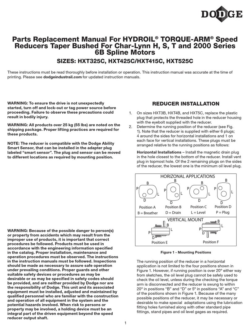
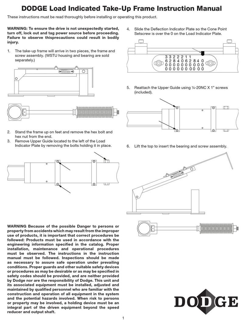
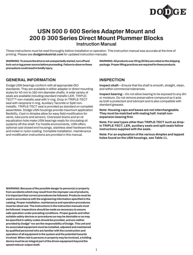
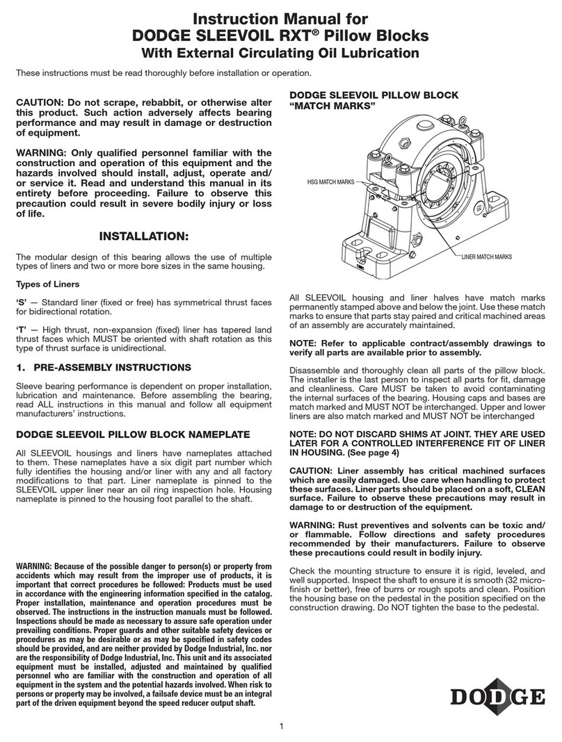
  9. Dodge SLEEVOIL RTL 3-7/16 User manual

Dodge SLEEVOIL RTL 3-7/16 User manual

1
WARNING: All products over 25 kg (55 lbs) are noted on the
shipping package. Proper lifting practices are required for
these products.
CAUTION: Do not scrape, rebabbitt or otherwise alter this
product. Such action adversely affects bearing performance
and may result in damage to or destruction of equipment.
SLEEVOIL RTL pillow blocks are designed for applications
requiring a bearing with high thrust load capacities and are
available in expansion and non-expansion types.
Exploded view of expansion pillow block (housing cap and liner
cap not shown). Non-expansion pillow block includes thrust
plate kit and split thrust collar.
Options include: thermocouple, circulating oil kit, heater and
thermostat, vibration detector kit, auxiliary seal kit and end
closure.
WARNING: Because of the possible danger to person(s) or
property from accidents which may result from the improper
use of products, it is important that correct procedures be
followed: Products must be used in accordance with the
engineering information specified in the catalog. Proper
installation, maintenance and operation procedures
must be observed. The instructions in the instruction
manuals must be followed. Inspections should be made
as necessary to assure safe operation under prevailing
conditions. Proper guards and other suitable safety devices
or procedures as may be desirable or as may be specified in
safety codes should be provided, and are neither provided
by Dodge nor are the responsibility of Dodge. This unit and
its associated equipment must be installed, adjusted and
maintained by qualified personnel who are familiar with the
construction and operation of all equipment in the system
and the potential hazards involved. When risk to persons
or property may be involved, a holding device must be an
integral part of the driven equipment beyond the speed
reducer output shaft.
DODGE®SLEEVOIL®RTL PILLOW BLOCKS
Sizes 3-7/16” through 12”
These instructions must be read thoroughly before installation or operation. This instruction manual was accurate at the time of
printing. Please see dodgeindustrial.com for updated instruction manuals.
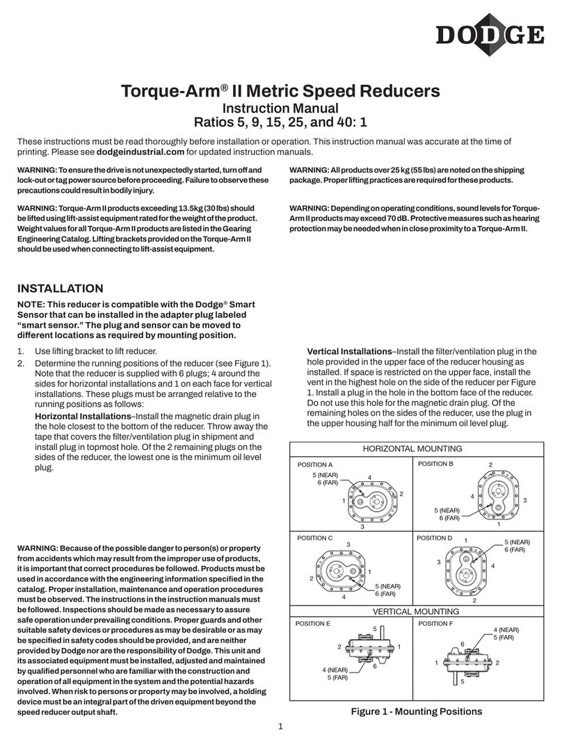
This manual is best suited for RTL Pillow Blocks. If your SLEEVOIL housing nameplate species “RTL SPHERICAL HOUSING,” use
manual MN3085. Dodge started manufacturing RTL SPHERICAL PILLOW BLOCKS in 2014.
PRE-ASSEMBLY INSTRUCTIONS
Refer to applicable contract/assembly drawings to verify that
all parts are available prior to assembly. Disassemble and
thoroughly clean all parts of the pillow block. The installer is the
last person to inspect all parts for t, damage and cleanliness.
Care MUST be taken to avoid contaminating the internal surfaces
of the bearing.
WARNING: Rust Preventatives and solvents can be toxic
and/or flammable. Follow directions and safety procedures
recommended by their manufacturers.
WARNING: Liner assembly has critical machined surfaces
which are easily damaged. Use care in handling to protect
these surfaces. Liner parts should be placed on a soft,
CLEAN surface.
For ease of installation, the housings and liners are split and
match-marked. The split halves are machined together and must
not be interchanged. The match-mark on the housing is found
near the joint in the grommet area. The match-mark on the liner
is found on the outer diameter of the pilot on one end of the liner.
2
INSTALL ATION OF BASES
WARNING: To ensure that drive is not unexpectedly started.
Turn off and lock out or tag power source before proceeding.
Failure to observe these precautions could result in bodily
injury.
Check mounting structure to insure it is rigid, level and well
supported. Position housing base on pedestal so oil gauge is
in position specied on construction drawing. Do NOT tighten
housing base to pedestal.
Apply oil to the spherical seats of the housing base.
Set liner base in housing base.
Because of the closely controlled liner to housing t, it may be
necessary to bolt the housing base down to allow the liner to slip
into the housing seat. Do a preliminary alignment check at this
time.
Make sure the two thermocouple/RTD holes in the liner
are aligned with the two thermocouple/RTD holes in the
housing. Apply oil to the liner bearing surface.
NOTE: Liner has been machined to close tolerances.
Scraping of bore is not necessary.
INSTALLATION OF SHAFT AND
THRUST COLLAR
Inspect shaft to ensure it is smooth (32 micro-inch RMS or better)
and free of burrs and rough spots. Standard shaft diametrical
tolerance should be nominal +.000/-.002” unless otherwise
specied on shaft detail drawing.
If bearing is non-expansion (xed) type, check thrust collar for
burrs and scratches. Use crocus cloth (NOT emery) to smooth
any scratches on the thrust collar faces.
If clamp-on type thrust collar is used, make sure joints of collar
are clean. Place both halves of thrust collar into shaft groove
and tighten clamp screws alternately and evenly to torque value
specied in Table 1.
NOTE: Set and jam screws are shipped separately.
The collar faces must be smooth with no offset at the split.
3
Tighten set screws to value specied in Table 1. Install and
tighten jam screws 1/10 of torque specified for set screws.
Oil shaft in the bearing area and CAREFULLY set shaft in place.
Table 1
RTL
SLEEVOIL
SIZE
THRUST COLLAR
CLAMP SCREW SET SCREW
SCREW SIZE
(SOC. HEX)
WRENCH
TORQUE
(IN.-LBS.)
SCREW SIZE
(SOC.HEX)
WRENCH
TORQUE
(IN.-LBS.)
3 7/16 RTL ¼ - 20NC 160 5/16 - 24NF 160
315/16 RTL ¼ - 20NC 160 5/16 - 24NF 160
4 7/16 RTL ¼ - 20NC 160 5/16 - 24NF 160
415/16 RTL 5/16 - 18NC 325 5/16 - 24NF 160
5 7/16 RTL 3/8 - 16NC 580 3/8 - 16NC 275
6 RTL ½ - 13NC 1425 3/8 - 16NC 275
7 RTL ½ - 13NC 1425 3/8 - 16NC 275
8 RTL ½ - 13NC 1425 5/8 - 11NC 1200
9 RTL 5/8 - 11NC 2800 5/8 - 11NC 1200
10 RTL ¾ - 10NC 5000 5/8 - 11NC 1200
12 RTL ¾ - 10NC 5000 5/8- 11NC 1200
The thrust collar must be centered in the cavity of the liner base.
INSTALLATION OF OIL RINGS
NOTE: Do NOT use oil rings if liner cap has baffles installed
in the oil ring grooves.
Oil rings are shipped disassembled with two extra screws. Place
oil rings around outside of liner base and over shaft.
NOTE: Oil ring halves are match-marked and MUST NOT be
interchanged.
Place oil ring around outside of liner base and over shaft.
Install oil ring screws to insure they are secure. Repeat for
second ring.
Make sure oil rings rotate freely on shaft.
INSTALLATION OF THRUST PL ATES
For non-expansion bearings:
Clean one set of babbitt faced thrust plates.
NOTE: Thrust plates are shipped in protective wax with the
babbitted faces on the outside. Be careful not to damage
the babbitted faces when peeling off the wax.
NOTE: Plates are matched halves and MUST NOT be
interchanged.
Carefully smooth any scratches on babbitted face with crocus
cloth (NOT emery cloth or sandpaper). Oil plate halves generously.
4
First, install the plate half without milled slots in the steel back.
Press the babbitted face against the thrust collar and rotate plate
around shaft into liner cavity.
Install retainer washer in groove in liner base. Rotate plate until
stopped by retainer washer.
Place the other thrust plate half (half with two milled slots in steel
back) against thrust collar, making sure babbitt faces thrust
collar.
Clean and oil the second thrust plate set and install in same
manner. It may be necessary to move the shaft slightly to obtain
enough clearance in the liner cavity to install the lower plate half.
CAUTION: The bearing is not yet fastened in place and can
be moved.
Total axial clearance between thrust plates and thrust collar is
.015 - .030 inches.
INSTALLATION OF LINER CAP
Apply oil to the bearing area of liner cap.
WARNING: If it ever becomes necessary to remove liner cap,
make certain that both upper thrust plate halves remain in
place next to the thrust collar. If a plate half should remain
in the liner cap it can drop from the liner and cause injury.
CAREFULLY locate liner cap on liner base. These SLEEVOIL
liners have match-marks permanently stamped at the joint near
one end. These match marks permanently insure that parts
stay paired and critical orientation of assemblies is maintained.
Makes sure oil rings rotate freely. End faces of liner should have
no appreciable offset.
Install cap screws and tighten alternately to torque given in Table
2.
NOTE: If liner cap on non-expansion bearing will not drop into
place, remove cap and reposition thrust plates tightly against
thrust collar. Reinstall liner cap.
Table 2
RTL
SLEEVOIL SIZE
LINER CAP BOLTS
THREAD SIZE TORQUE
(IN.-LBS.)
3-7/16 5/16 - 18 132
3-15/16 5/16 - 18 132
4-7/16 5/16 - 18 132
4-15/16 5/16 - 18 132
5-7/16 5/16 - 18 132
6 3/8 - 16 240
7 ½ - 13 600
8 ½ - 13 600
9 ½ - 13 600
10 ¾ - 10 2100
12 ¾ - 10 2100
5
Check alignment of pillow block by noting clearance between
housing and shaft at each end of the housing. Clearance should
be uniform within 1/32”. Shim bearing pedestal where possible;
otherwise, use full length shims under base as required.
Alignment of pillow block should be accurate to prevent the seals
from rubbing.
Tighten the four pedestal bolts to torque value given in Table 3.
Shaft should rotate freely.
INSTALLATION OF OIL SEALS
Cut the O-ring (rubber cord) and wrap it around the shaft inside
the seal groove. If the O-ring is too large, cut it to t the shaft.
For most effective sealing, ends of O-ring must meet. Cement or
glue the ends together. Lubricate O-ring with oil or grease.
Apply a thin coat of heavy oil or light grease in the housing seal
grooves to extend seal life.
Disassemble one seal and place one half on shaft with inger
facing liner. Locate O-ring in seal groove and rotate seal half
around shaft into housing base groove.
Install other half of seal and tighten screws to torque given in
Table 3. Check to make sure the seal will slide along the shaft
with minimum effort to allow for shaft expansion. Align the seal in
the middle of the seal groove.
Install second seal in same manner. If end closure is to be used,
the neoprene disc is to be installed on one end at this time
instead of the bearing seal. Consult construction drawing.
Table 3
RTL SLEEVOIL
SIZE
HOUSING/PEDESTAL BOLTS SEAL CLAMP SCREWS
THREAD
SIZE
TORQUE
(IN.-LBS.)
THREAD
SIZE
TORQUE
(IN.-LBS.)
3-7/16
3-15/16
3/4
7/8
2100
2040
10–24
10–24
12
12
4-7/16
4-15/16
1
1
3000
3000
10–24
10–24
12
12
5-7/16
6
1-1/8
1-1/4
4200
6000
1/4–20
1/4–20
33
33
7
8
1-1/2
1-3/4
10000
11500
5/16–18
5/16–18
65
65
9
10
12
1-3/4
2
2
11500
15000
15000
3/8–16
3/8–16
3/8–16
120
120
120
INSTALLATION OF HOUSING CAP
Back off the plunger screw as far as possible.
Along the outer contour of the housing base, apply the supplied
LOCTITE® 515 or an equivalent sealant to the joint. CAREFULLY
place the housing cap on the base, and take special precautions
to prevent seal damage.
The plunger screw must remain loose until the housing bolts
have been tightened.

This manual suits for next models

10

Other Dodge Industrial Equipment manuals

Dodge Tigear-2 User manual

Dodge

Dodge Tigear-2 User manual

Dodge S-2000 User manual

Dodge

Dodge S-2000 User manual

Dodge 11 D User manual

Dodge

Dodge 11 D User manual

Dodge Quantis MSM/RHB 38 User manual

Dodge

Dodge Quantis MSM/RHB 38 User manual

Dodge ISNX User manual

Dodge

Dodge ISNX User manual

Dodge Quantis Ultra Kleen User manual

Dodge

Dodge Quantis Ultra Kleen User manual

Dodge Sleevoil STL 9 PLAIN User manual

Dodge

Dodge Sleevoil STL 9 PLAIN User manual

Dodge Tigear-2 User manual

Dodge

Dodge Tigear-2 User manual

Dodge SLEEVOIL 2-15/16 User manual

Dodge

Dodge SLEEVOIL 2-15/16 User manual

Dodge SLEEVOIL RXT User manual

Dodge

Dodge SLEEVOIL RXT User manual

Dodge TXT/ABHS Service manual

Dodge

Dodge TXT/ABHS Service manual

Dodge USN 500 Series User manual

Dodge

Dodge USN 500 Series User manual

Dodge Imperial User manual

Dodge

Dodge Imperial User manual

Dodge CPLI-400X12-TUFR User manual

Dodge

Dodge CPLI-400X12-TUFR User manual

Dodge TA0107L User manual

Dodge

Dodge TA0107L User manual

Dodge SCXT 225 User manual

Dodge

Dodge SCXT 225 User manual

Dodge Torque-Arm II TA0107LM Quick guide

Dodge

Dodge Torque-Arm II TA0107LM Quick guide

Dodge Torque-Arm II TA0107LM User manual

Dodge

Dodge Torque-Arm II TA0107LM User manual

Dodge SLEEVOIL RXT User manual

Dodge

Dodge SLEEVOIL RXT User manual

Dodge USAF User manual

Dodge

Dodge USAF User manual

Dodge Sleevoil STL User manual

Dodge

Dodge Sleevoil STL User manual

Dodge Torque-Arm II User manual

Dodge

Dodge Torque-Arm II User manual

Dodge HYDROIL TORQUE-ARM HXT325C Use and care manual

Dodge

Dodge HYDROIL TORQUE-ARM HXT325C Use and care manual

Dodge Quantis MSM User manual

Dodge

Dodge Quantis MSM User manual

Popular Industrial Equipment manuals by other brands

ABB +Q957 user manual

ABB

ABB +Q957 user manual

G.B.C BASIC EDGE 50 instruction manual

G.B.C

G.B.C BASIC EDGE 50 instruction manual

Tronair Batpak 11-6602-1000 Operation & service manual

Tronair

Tronair Batpak 11-6602-1000 Operation & service manual

Pilz PNOZ mi2p Operation manual

Pilz

Pilz PNOZ mi2p Operation manual

Clemco Zero BNP 6012 manual

Clemco

Clemco Zero BNP 6012 manual

Erskine Attachments V-Plow Operator's manual

Erskine Attachments

Erskine Attachments V-Plow Operator's manual

ABB HT610965 Operation manual

ABB

ABB HT610965 Operation manual

Morra MH 540 user manual

Morra

Morra MH 540 user manual

Eaton S090ST manual

Eaton

Eaton S090ST manual

GRIGGIO G 240 P4 instructions

GRIGGIO

GRIGGIO G 240 P4 instructions

Nexen AIR CHAMP HT45 user manual

Nexen

Nexen AIR CHAMP HT45 user manual

WTE V5 installation manual

WTE

WTE V5 installation manual

ABB HT845232 Operation manual

ABB

ABB HT845232 Operation manual

SMC Networks CJP Series Operation manual

SMC Networks

SMC Networks CJP Series Operation manual

JohnDow Industries JDI-AFT58 Operator's manual

JohnDow Industries

JohnDow Industries JDI-AFT58 Operator's manual

IMB MB9016A instruction manual

IMB

IMB MB9016A instruction manual

Clarke CUMB1 Assembly & operating instructions

Clarke

Clarke CUMB1 Assembly & operating instructions

amiad Arkal Spin Klin 2 user guide

amiad

amiad Arkal Spin Klin 2 user guide

manuals.online logo
manuals.online logoBrands
  • About & Mission
  • Contact us
  • Privacy Policy
  • Terms and Conditions

Copyright 2025 Manuals.Online. All Rights Reserved.