HyQuest Solutions PVD100 User manual

HyQuest Solutions Pty Ltd
1
QUALITY
SYSTEM
ISO: 9001
CERTIFIED
OPERATING MANUAL
PVD100
Current Meter Counter
HYQUEST SOLUTIONS PTY LTD
48-50 Scrivener St, Warwick Farm, NSW 2170, AUSTRALIA
Phone: +61 2 9601 2022 Fax: +61 2 9602 6971
Email: sales@hyquestsolutions.com.au
Web: www.hyquestsolutions.com.au

HyQuest Solutions Pty Ltd
Point Velocity Display - Model PVD100
© Copyright 2Issue 1.00 4 Apr, 2007
TABLE OF CONTENTS
1.Introduction........................................................................................ 3
2.1Overview............................................................................................................... 4
3.Installation.......................................................................................... 5
3.1Hardware Connections ....................................................................................... 5
4.Operation............................................................................................ 6
4.1Description of Controls....................................................................................... 6
4.1.1Pushbuttons.......................................................................................................... 6
4.1.2Indicator LEDs .................................................................................................... 7
4.1.3Factory Default Settings...................................................................................... 7
4.2The Main Display ................................................................................................ 8
4.3The Menus............................................................................................................ 11
4.3.1Special Operating Functions .............................................................................. 11
4.3.2Velocity / Counts.................................................................................................. 11
4.3.3Feet / Meters......................................................................................................... 11
4.3.4Magnetic Head / Cat whisker............................................................................. 12
4.3.5Normal / Slow....................................................................................................... 12
4.3.6Buzzer On/Off...................................................................................................... 12
4.3.7Measurement Time.............................................................................................. 13
4.3.8Bluetooth®Communications............................................................................... 13
4.3.9Calibrate............................................................................................................... 14
4.3.10Comms Test.......................................................................................................... 15
4.3.11Dwell Measurement............................................................................................. 16
4.3.12Spin Test............................................................................................................... 17
4.3.13 Battery Condition ................................................................................................. 18
4.3.14Meter Selection .................................................................................................... 19
4.3.15Software Version ................................................................................................. 20
4.4Serial Communications Interface ...................................................................... 21
4.4.1Data Conversion Example.................................................................................. 23
4.4.2The User Serial Interface Program.................................................................... 25
4.4.3Quick-Step Procedure for the User Serial Interface Program........................ 29
4.4.4Operating the Special Functions Using Serial Communications .................... 31
4.5Changing the Batteries........................................................................................ 32
4.6Maintenance and Repair Procedure.................................................................. 32
5.Specifications...................................................................................... 33
Appendix A Capturing a Spin Test............................................................... 35
Appendix B Measuring Meter Dwell ............................................................ 40
Appendix C Serial Port Echo Command ..................................................... 41
Appendix D Example Calibration Certificate.............................................. 42

HyQuest Solutions Pty Ltd
Point Velocity Display - Model PVD100
© Copyright 3Issue 1.00 4 Apr, 2007
1. Introduction
(The functions described in this manual apply to PVD100 software Version 2.5)
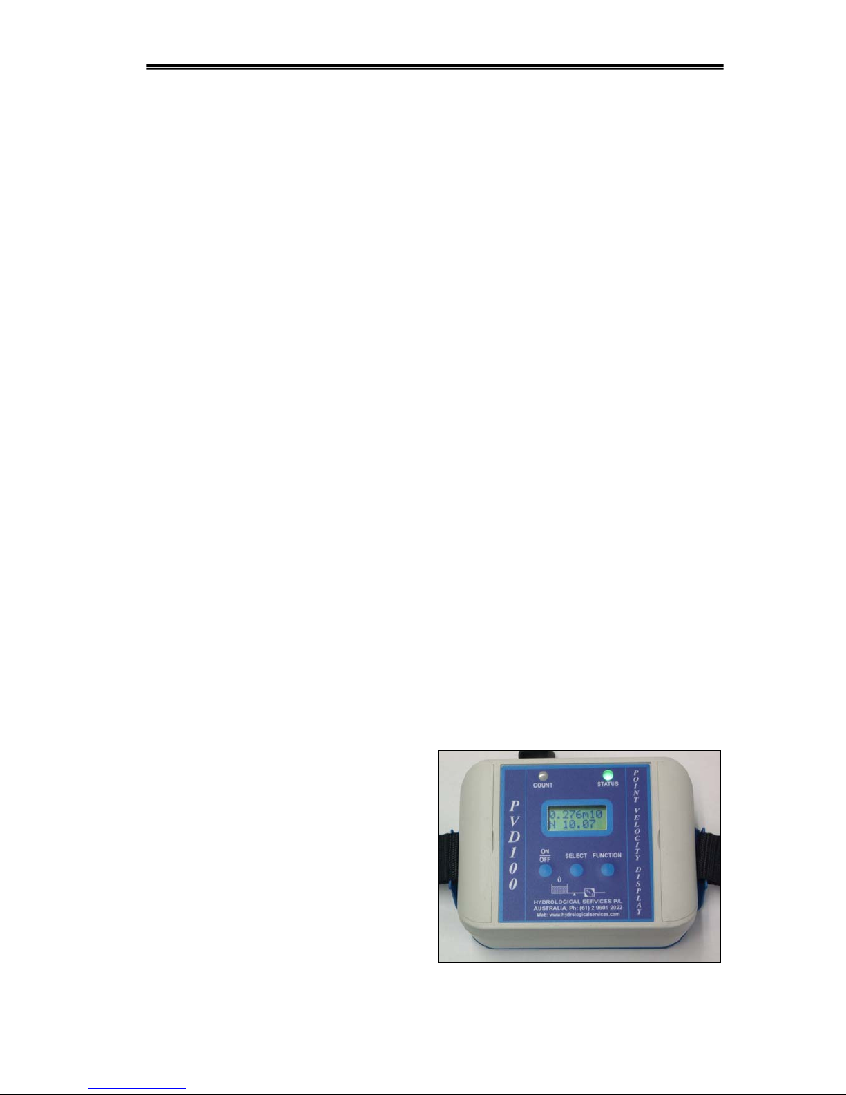
The HyQuest Solutions Point Velocity Display (PVD100) is a small electronic device that
can be used to measure flow velocity from most any mechanically rotating current meter. A
superior feature of the PVD100 is its ability to "clean" the signal and interface directly to a
PDA, PocketPC, or other computing device and provide serial data that can be used by the
external device to compute discharge. Meters using a cat whisker head and ball and wire
contact to perform a mechanical switch closure can be used with the PVD100 to produce a
clean, noise-free signal. To measure and compute velocity, the PVD100 provides a User
Serial Interface Program (USIP). This USIP is used to enter the rating of the current meter
and can support up to two meters with each meter having up to three rating equations with
three rotations/sec ranges.
The PVD100 operates with two AA batteries and can mount directly onto a top-setting
wading rod. It offers connectivity between the current meter and a hand-held computer using
either a connecting lead or an optional Bluetooth®wireless interface. Commands can be sent
to the PVD100 to perform a measurement and make operating selections. The PVD100 can
operate with current meter velocities from less than 0.015 m/sec to more than 6.1 m/sec for a
Price AA meter. The PVD100 also provides a slow-speed mode to improve measurements
with extremely slow rotating current meters [velocities less than 0.076 m/sec]. The PVD100
does not need to be connected to an external device to operate. The visual indicators, LCD
and internal buzzer of the PVD100 can be used to make a conventional current meter
measurement and compute water velocity.
As you continue to read this manual, many features and operating capabilities of the PVD100
will be revealed and described. The PVD100 is extremely easy to use and yet versatile
enough to offer selections to operate in a wide variety of scenarios and field settings. Its
lightweight design allows the unit to connect directly onto the phone jack connection of a top-
setting wading rod giving the user a nearly ‘hands free’ feel of operation. A single press of a
button can begin a measurement. With its optional Bluetooth®capability, true ‘wireless’
connectivity can be made.
The software functions described in these instructions are sufficiently detailed for developers
to integrate the PVD100 with other hardware and software devices giving users the ability to
develop their own applications.
As an added benefit, whenever the PVD100
is inactive, the PVD100 will automatically
turn itself Off after 5 minutes to help
conserve the batteries. When the PVD100
turns Off, all important settings are saved in
memory, eliminating the burden of re-setting
up the device when the unit is turned back
On. To turn it On, simply press the ON/OFF
button and all previous settings are restored
ready for the user to begin a measurement.

HyQuest Solutions Pty Ltd
Point Velocity Display - Model PVD100
© Copyright 4Issue 1.00 4 Apr, 2007
2. Product Overview
2.1 Overview
The PVD100 can measure and display velocity. Velocity can be either displayed in
meters/sec (m/sec) or feet/second (ft/sec) and is chosen by the user in a menu. When a
measurement is being made, the PVD100 counts contact closures, measures elapse time, and
computes velocity to a precision of 0.001 m/sec or 0.01 ft/sec. The velocity is computed
based on a selection of a meter rating again chosen from a menu. During a measurement, the
PVD100 sends through the serial port the number of accumulating meter contact closures and
elapsed time at 1-second intervals. At the end of the measuring period, typically set for 40
seconds, a final count of the total number of contact closures and total measurement time is
transmitted. From this data, a connected hand-held computer with an appropriate applications
program can compute velocity for a discharge computation.
One of the most important operating features of the PVD100 is the ability to signal process
each contact closure. Contact closures from any type of meter are inherently noisy causing
miscounting or double counting. The PVD100 samples the input signal from the connected
meter and examines the signal to determine if a contact closure has occurred and if successive
signals are of the same characteristics. The PVD100 then determines contact closure
conditions and either counts the signal closure or eliminates the condition as a noise pulse and
does not count the signal. For cat whisker contacts, this becomes extremely important since
cat whisker contacts offer the poorest quality for marking and counting rotations.
The PVD100 offers (2) modes of operation, i.e. NORMAL and SLOW speed mode.
NORMAL is selected for meter rotations >0.076 m/sec while SLOW mode is for velocities
below 0.076 m/sec. To improve noise rejection, the sample rate of the input signal at the
SLOW speed mode (lower velocities) is 1/10 of the sampling rate that occurs during
NORMAL mode. This slower sampling rate improves performance for back rotations and
corroded whisker contacts at extremely low meter cup rotations. It is important to know that
the PVD100 offers operational overlap at this 0.076 m/sec velocity selection in either mode
and therefore it is not necessary for the operator to know precisely the velocity of water for
selecting either mode.
Another important feature of the PVD100 is the ability to detect faulty connections from the
meter through the wading rod to the connected PVD100. During power up of the PVD100, a
calibration of the input signal is performed. If a connection short is detected or other
condition such as faulty input electronics, the PVD100 signals the operator of the condition
(by flashing the COUNT indicator) until the faulty condition is removed. Open circuit fault
conditions are observed simply as a failure to detect a contact closure. A very important
feature of the PVD100 is the ability to detect a signal short during a measurement. If such a
condition is detected, the ‘*’ symbol is displayed until the fault condition is removed.
Importantly is the appearance of the ‘*’ symbol after the measurement to show the operator
that a fault condition occurred during the measurement and that the measurement should be
repeated. The measurement data that is transmitted through the serial port is also flagged to
indicate a faulty measurement.

HyQuest Solutions Pty Ltd
Point Velocity Display - Model PVD100
© Copyright 5Issue 1.00 4 Apr, 2007
3. Installation
3.1 Hardware Connections
Current Meter Input Connector
The PVD100 provides two banana plug
connections to the current meter.
The DB9 female connector on the PVD100,
provides the RS232 interface and the signal
driver output.
RS232 Interface – This interface is designed to directly connect to a handheld computer with
an RS232C interface. Use the Comms Test function to test this interface.
Pin PVD100 Signal Description Direction
1 N.C.
2 Tx Data (RS232 data output)
3 Rx Data (RS232 data input)
4 N.C.
5 Data Ground 0V
6 N.C.
7 N.C.
8 N.C.
9 Signal Driver (O/C output)
Signal Driver Interface—Pin 9 provides an interface to other instruments that may use a
current meter to perform velocity or flow measurements. Examples include the JBS
Instruments’ AquaCalc and Sutron’s DMX Discharge Measurement Recorders. The signal
provided through this connection simulates a current meter contact closure. Whenever a
contact closure is detected from the current meter, the PVD100 outputs through this
connector, a fixed pulse-width driving signal that represents the contact closure. The signal
driver is an open-drain Field Effect Transistor (FET) that will act like a switch. The signal is
processed by the PVD100.To verify operation of this signal with other equipment, use the
Comms Test function which simulates a contact closure and operates this output.
CAUTION : Do not connect any type of DC voltage directly to pin 1 without a limiting
resistor as this will permanently damage the driver circuit.

HyQuest Solutions Pty Ltd
Point Velocity Display - Model PVD100
© Copyright 6Issue 1.00 4 Apr, 2007
4. Operation
4.1 Description of Controls
4.1.1 Pushbuttons
The PVD100 has three front panel buttons that are used to turn power On and Off, view
menus, and choose operating settings. The buttons are labeled as follows:
ON/OFF – This button is the far left button on the front panel and is used to turn power
On and Off on the PVD100. It is also used to quit from operating functions
or exit from selections.
To turn On the PVD100, depress and release the ON/OFF button. The
PVD100 will turn On and go through a short initialization restoring settings
and selections. The PVD100 will then perform a self-calibration. Some
settings and selections are stored permanently in memory even when the
batteries are changed.
To turn Off the PVD100, press and hold the ON/OFF button for more than 3
seconds. The PVD100 will turn off all indicators and the LCD, and then
permanently store all user selectable settings. These settings will be
automatically restored the next time the PVD100 is powered on.
The PVD100 will automatically shut off after (5) minutes of no activity
(i.e. no meter contact closures, no serial port activity, no button presses and
Bluetooth switched off or in Discover mode.)
SELECT – This center located button is used to perform selections within the different
menus, and for special operating functions, this button is used to begin or
start an operation.
FUNCTION – This button, located on the far right of the front panel, is used to go into a
selection menu. If a measurement is not in progress, depressing this button
will bring up a series of menus for choosing operating selections and
functions.
When the PVD100 is first turned on, previously selected settings are restored and the battery
is checked. When the battery-check message appears on the LCD, the operator is required to
acknowledge the message by depressing any button (i.e. ON/OFF, SELECT, or FUNCTION).
After acknowledging the battery condition message, the PVD100 performs a self-calibration.
This calibration automatically adjusts the internal electronics for the conductivity of the water
and check for any meter fault conditions. After this calibration, the PVD100 shows the Main
display.
NOTE : When all 3 buttons on the PVD100 are held down simultaneously, the
electronics performs a hardware reset, which is the same as removing and reinstalling
the batteries!

HyQuest Solutions Pty Ltd
Point Velocity Display - Model PVD100
© Copyright 7Issue 1.00 4 Apr, 2007
4.1.2 Indicator LEDs
The PVD100 provides two LED indicators to show the unit is operating and to indicate
current meter contact closures. Both indicators also show cable faults and other operating
conditions of the PVD100. The following is a brief description for each indicator.
COUNT (Orange LED)—This indicator will flash whenever a contact closure from the meter
has been detected. It also will indicate when special functions such as the “Meter Dwell
Measurement” are being performed or the User Serial Interface program has been invoked.
In the case of a detected fault, the indicator will turn On and stay On until the fault is cleared.
OPERATING STATUS (Green/Red/Blue LED)—This indicator remains illuminated
whenever the PVD100 is turned On and showing the operating status mode. The LED has
three colors showing the type of meter (Magnetic Head or Cat Whisker Head) selected as
well as Bluetooth®operational status. Green indicates the Magnetic Head is selected and red
indicates the Cat Whisker Head is selected. The operating default (power-up setting) is
Magnetic Head. The indicator also shows the operating mode. If the indicator is not
blinking, then the operating mode is ‘Normal’. If the indicator is blinking rapidly, then the
operating mode is ‘Slow’.
4.1.3 Factory Default Settings
The PVD100 can be set with Factory Settings (or defaults) and these settings allow the
PVD100 to operate with preset conditions. These settings can be changed. To set the
PVD100 with Factory Settings, depress and hold the FUNCTION button, then turn On the
PVD100. When the ‘Factory Settings’ message appears on the display, the FUNCTION
button can be released.
The following is a list of the Factory Settings:
-Magnetic Head/Cat Whisker Head selection set to MAG, Magnetic Head meter
-STATUS is set to Normal speed
-Measurement Time is set to 40-seconds
-The Buzzer is turned Off
-The following are the rating equation defaults:
oA: S/N 1000-00 (Meter ‘A’ Serial Number)
o1 Rating (Number of ratings or equations)
o1: 2.2048(n)+0.0178 (Rating equation, n= rotations/sec)
oB: S/N 2000-00 (Meter ‘B’ Serial Number)
o1 Rating (Number of ratings or equations)
o1: 0.9604(n)+0.0312 (Rating equation, n=rotations/sec)
-Meter ‘A’ selected for velocity computation
-Feet – Meters/second display set to ‘Feet’/sec
-All other settings are initialized to ‘0’ or turned Off

HyQuest Solutions Pty Ltd
Point Velocity Display - Model PVD100
© Copyright 8Issue 1.00 4 Apr, 2007
M XXX 40
N XXX.XX *
M XXX 40
N XXX.XX *
M XXX 40
N XXX.XX *
M XXX 40
N XXX.XX *
4.2 The Main Display
The following describes the Main display presentation on the LCD. Note: This display
presentation is shown when the Menu selection VELOCITY/COUNTS is set to COUNTS.
This display position shows the selection of the meter contact
switch type. The selection can be Mfor a Magnetic Head
contact or Cfor a Cat Whisker contact switch.
This display position shows the selection of the operating
speed. The operating speed (or mode) selection can be Nfor
Normal Speed (for velocities >0.076 m/sec) or Sfor Slow
Speed (velocities <0.076 m/sec).
This display position shows the total accumulating meter
contact counts during a measurement. Maximum number that
can be shown is 999. Whenever meter contact counts exceed
999, the PVD100 will continue to count but the most
significant number position will begin to show special
characters such as ‘:’ or ‘;’, etc. These characters indicate to
the operator that a rollover count of ‘999’ has occurred.
This display position shows the total elapsed time of the
measurement. During a measurement, the display shows
elapsed time in seconds. When the measurement is completed,
the display shows the total elapsed time to a tenth of second. If
any measurement exceeds 300 seconds of elapsed time, the
display will show the final elapsed time only in seconds when
the measurement is completed. A ‘^’ character is shown in front of the accumulating elapsed
time during and after completion of the measurement to indicate elapsed time has exceeded
300 seconds. The maximum displayed number is 999, however the PVD100 will ‘roll-over’
to ‘0’ and continue to count until a meter contact closure is detected. To terminate the
measurement upon the next meter contact closure, depress the ‘SELECT’ button. To
terminate the measurement at any time and stop the count, depress and release the ‘ON/OFF
button. After the measurement, to clear the total elapsed time, depress and release the
ON/OFF button while in the Main display.

HyQuest Solutions Pty Ltd
Point Velocity Display - Model PVD100
© Copyright 9Issue 1.00 4 Apr, 2007
M XXX 40
N XXX.XX *
M XXX 40
N XXX.XX *
This display position shows the selection of the measuring
interval. The measuring interval is chosen within a selection
menu. The measuring interval is selected in 10-second
increments to a maximum of 90 seconds. A measuring interval
selection of ‘0’ means a ‘continuous’ measurement with no
time limit. With this time interval selection, the operator must
depress the ‘SELECT’ button to stop the measurement at the next meter contact closure or the
‘ON/OFF’ button to simply stop and end the measurement.
This display position shows the indication of a current meter
fault. When the indicator appears, a meter fault has been
detected. When the fault is cleared, the indicating character
will disappear. If a fault has been detected during the
measurement, the symbol will appear at the end of the
measurement and will remain shown on the display until a
new measurement is made.
In Summary (VELOCITY/COUNTS selected for COUNTS)
M XXX 40
N XXX.XX *
M = Mag Head
C = Cats Whiske
r
Contact Counts
Measuring Interval in Secs
0 = Continuous
N = Normal Speed
S = Slow S
p
ee
d
Elapsed Time in Secs
Blank = OK
* = Fault Detected

HyQuest Solutions Pty Ltd
Point Velocity Display - Model PVD100
© Copyright 10 Issue 1.00 4 Apr, 2007
The following describes the Main display presentation on the LCD when the Menu selection
VELOCITY/COUNTS is set to VELOCITY.
This display position shows the units as either ‘m’ for
meters/second or ‘f’ for feet/second. The selection is
performed in the FEET/METERS menu selection.
This display position shows velocity. Velocity precision
(number of decimal places) is presented based on the
selection of either feet/second or meters/second. If the
FEET/METERS selection menu is set for FEET, the display
will show velocity to two decimal places, while if the
selection is set to METERS, the display will show velocity to
three decimal places.
(Trick: if you want to get more resolution in the display of feet/second, simply select meters/second
knowing that the rating equation is entered as feet/second. When ratings are entered, they are
dimensionless; hence the calculation is performed without units. You must know that the rating is
entered as feet/second even though the display shows meters/second.)
In Summary (VELOCITY/COUNTS selected for VELOCITY)
X. XX f 40
N XXX.XX *
Units: f = feet/sec
m= meters/sec
Velocity:
-in meters: X.XXX m
-in feet: X.XX f Measuring Interval in Secs
0 = Continuous
N = Normal Speed
S = Slow S
p
ee
d
Elapsed Time in Seconds
Blank = OK
* = Fault Detected
X.XXf 40
N XXX.XX *
X.XXXm40
N XXX.XX *

HyQuest Solutions Pty Ltd
Point Velocity Display - Model PVD100
© Copyright 11 Issue 1.00 4 Apr, 2007
FEET
METERS
4.3 The Menus
To review or choose operating conditions and settings, a series of menus provide for each
selection or function. To enter a menu, depress and release the FUNCTION button. Each
time the FUNCTION button is depressed, a new menu is presented. To make a selection
within a menu, depress the SELECT button. For most menus, an arrow character, ‘→‘,
points to or shows the present selection within that menu. To exit from a menu at any time,
depress and release the ON/OFF button. To continue through the menus, depress and release
the FUNCTION button. Menus can only be viewed when a measurement is not being
performed.
4.3.1 Special Operating Functions
Within the PVD100 are special operating functions that offer tools for adjusting the current
meter and measuring its performance. These special functions are described in order of
appearance within the menu list. Refer to Section 4.4.4 below for the details of operating
these functions using the serial communications interface.
4.3.2 Velocity / Counts
This is the first menu. The menu allows selection of the main
display to show velocity; or counts and meter type selection.
Use the FUNCTION button to select this menu, then press
SELECT to toggle between Velocity (spelled VELOCTY in
menu) or Counts. Press ON/OFF to return to the main display
or press FUNCTION to step to the next menu item.
4.3.3 Feet / Meters
Use the FUNCTION button to select this menu, then press
SELECT to toggle between Feet or Meters. Press ON/OFF to
return to the main display or press FUNCTION to step to the
next menu item.
VELOCTY
COUNTS

HyQuest Solutions Pty Ltd
Point Velocity Display - Model PVD100
© Copyright 12 Issue 1.00 4 Apr, 2007
MAGHEAD
CATWSKR
NORMAL
SLOW
ON-BUZR
OFF
4.3.4 Magnetic Head / Cat whisker
Allows selection between a Magnetic Head contact or a Cat
Whisker contact switch. Use the FUNCTION button to select
this menu, then press SELECT to toggle between Magnetic
Head or Cat Whisker contact. Press ON/OFF to return to the
main display or press FUNCTION to step to the next menu
item.
One of the most important operating features of the PVD100 is the ability to signal process
each contact closure. Contact closures from any type of meter are inherently noisy causing
miscounting or double counting. The PVD100 samples the input signal from the connected
meter and examines the signal to determine if a contact closure has occurred and if successive
signals are of the same characteristics. The PVD100 then determines contact closure
conditions and either counts the signal closure or eliminates the condition as a noise pulse and
does not count the signal. For cat whisker contacts, this becomes extremely important since
cat whisker contacts offer the poorest quality for marking and counting rotations.
4.3.5 Normal / Slow
Use the FUNCTION button to select this menu, then press
SELECT to toggle between Normal or Slow. Press ON/OFF
to return to the main display or press FUNCTION to step to
the next menu item.
The PVD100 offers (2) modes of operation, i.e. NORMAL
and SLOW speed mode. NORMAL is selected for meter
rotations >0.076 m/sec while SLOW mode is for velocities below 0.076 m/sec. To improve
noise rejection, the sample rate of the input signal at the SLOW speed mode (lower
velocities) is 1/10 of the sampling rate that occurs during NORMAL mode. This slower
sampling rate improves performance for back rotations and corroded whisker contacts at
extremely low meter cup rotations. It is important to know that the PVD100 offers
operational overlap at this 0.076 m/sec velocity selection in either mode and therefore it is not
necessary for the operator to know precisely the velocity of water for selecting either mode.
When in SLOW mode, the status LED flickers, and the sounder beeps longer whenever the
whisker contacts are made.
4.3.6 Buzzer On/Off
Use the FUNCTION button to select this menu, then press
SELECT to toggle between Buzzer On or Off. Press ON/OFF
to return to the main display or press FUNCTION to step to
the next menu item.

HyQuest Solutions Pty Ltd
Point Velocity Display - Model PVD100
© Copyright 13 Issue 1.00 4 Apr, 2007
TIME
40 SEC
OFF - BT
ON COM
BLUTOOTH
DISCOVER
4.3.7 Measurement Time
Use the FUNCTION button to select this menu, then press
SELECT to increment the time in 10 second steps between 00
and 90 seconds. At this instant the selection is saved, so either
press ON/OFF to return to the main display or press
FUNCTION to step to the next menu item.
This is the nominal measurement time used when taking a
current meter reading. When the time is set to 00 seconds, the timer runs until stopped
manually by pressing the SELECT button, which completes the measurement at the next
contact closure.
4.3.8 Bluetooth®Communications
Bluetooth®provides for a wireless link to an external device such as a PocketPC (PDA) or
laptop that eliminates the serial RS-232 cable link connection. Bluetooth®is a wireless
standard (IEEE 802.14) that offers a transparent serial port protocol for communication.
Since the PVD100 can output data and be controlled using the RS-232 serial interface, the
physical cable connection can be eliminated using Bluetooth®. When the PVD100 is turned
On, the PVD100 determines if Bluetooth®is installed. If available, Bluetooth®can be
enabled and ‘discovered’ by another Bluetooth®device to establish a connection. Set the
external device’s communication protocol in the following manner:
Baud Rate : 19200
Data bits : 8
Stop bits : 1
Parity : None
Flow control : None
Use the FUNCTION button to select this menu, then press
SELECT to toggle between Bluetooth®On and Off, then
press ON/OFF to enable Bluetooth®.
The following display presentation is shown when setting up
and enabling Bluetooth®.
When this display is presented, the STATUS indicator will
be blue and flashing at a rate of two quick flashes every two
seconds. When another Bluetooth®compatible device is in
proximity of the PVD100, and the devices application requests a connection, each
automatically establishes the Bluetooth®serial interface protocol. When the connection has
been established, the following display is shown on the PVD100 display:

HyQuest Solutions Pty Ltd
Point Velocity Display - Model PVD100
© Copyright 14 Issue 1.00 4 Apr, 2007
CALIBRT
YES
CONNECTD
When a wireless connection is made, the STATUS indicator
will show a solid blue color continuously – and the display
will read “CONNECTD” for a few seconds before
automatically jumping to the Main Display.
When making a connection with another Bluetooth®device for the first time, first examine
and prepare the required enabling features of the external device for Bluetooth® connection.
Enable the PVD100 Bluetooth®function and allow the external device to ‘discover’ the
PVD100. When the external device makes ‘discovery’, the user must select the PVD100
within the device’s menu setup and enable the connection. The external device should
respond with a ‘connected’ message. The PVD100 can now be used in a normal manner. All
serial data sent from the PVD100 will be transmitted via Bluetooth®. The connection can be
disengaged by selection in the ‘-BT COM’ menu. The operator must monitor the integrity of
the connection from the external device. If the connection becomes broken, the PVD100 will
revert back to Bluetooth®DISCOVER mode. This message will alert the operator of a
disconnection between the PVD100 and the external device. Connection will have to be
rediscovered by the external device. Any active measurement occurring during a broken
communications link will terminate and the measurement will need to be retaken. The
PVD100 will not automatically power down when Bluetooth®is enabled and connected. If
Bluetooth®is On (or ‘connected’) when the PVD100 is manually powered Off, the PVD100
will go directly into ‘DISCOVER’ mode when the PVD100 is turned back On. If the
PVD100 is in a ‘DISCOVER’ mode, the PVD100 will remain in this mode for 5 minutes,
then automatically turn Off if the PVD100 does not become ‘connected’. However, when the
PVD100 is turned back On, the PVD100 will automatically go into ‘DISCOVER’ mode.
4.3.9 Calibrate
A calibration is performed automatically when the PVD100 is turned on and when a
measurement is actioned through the comms interface. Performing a calibration within the
menu can be used to check the input electronics of the PVD100 for proper operation when
not connected to a meter. It is also useful to check the connectivity to the current meter. If a
detectable fault is found, the COUNT indicator will turn On and stay On and the STATUS
indicator will turn On and Off to indicate a connection short or some other electronics fault.
When the fault is cleared, the indicators will reflect their fault-free operating condition.
Finally, it may be necessary to recalibrate the PVD100 in areas where the water has a high
conductivity. Use this function when the meter and wading rod or meter mounting are
completely in the water. This will insure a proper calibration and adjustment of the PVD100
to the water conductivity prior to making a measurement.
To perform a manual calibration, use the FUNCTION button
to select this menu, then press SELECT to toggle to YES and
perform the calibration. (This takes less than 1 second)

HyQuest Solutions Pty Ltd
Point Velocity Display - Model PVD100
© Copyright 15 Issue 1.00 4 Apr, 2007
COMTEST
YES
SER PORT
TEST
4.3.10 Comms Test
The ‘Serial Port Test’ function, called ‘COMTEST’ in the menu, provides a way to test the
setup of the serial communications interface between the PVD100 and an external device
connected (cabled or wireless) to the PVD100.
Set the external device’s communication port as follows :
Baud Rate : 19200
Data bits : 8
Stop bits : 1
Parity: None
Flow control : None
Use the FUNCTION button to select the COMTEST menu,
then press SELECT to toggle the arrow to YES, then press
ON/OFF to start the test.
When the test is invoked, the display will read “SER PORT
TEST” and the single ASCII character ‘1’ is transmitted
through the serial interface. If the connected device’s serial
communications interface is properly configured, the character
will be received. The character is sent at a rate of about two
times a second. Depressing and holding the ‘SELECT’ button
for more than two seconds can send an alternate ASCII
character string. This alternate character string represents the
data string format that would normally be sent through the
serial interface when making a current meter measurement. To deselect this alternate
character string, depress and hold the ‘SELECT’ button again until the single character ‘1’
appears. The screen capture in the figure
to the left, shows both character strings
sent through the serial interface while
this test is being performed. The string
sent through the serial interface can be
viewed when using the Microsoft
program HyperTerminal. When the test
is invoked, the ‘COUNT’ indicator
flashes and the Signal Driver O/C output
operates (to simulate a contact closure)
and the ‘STATUS’ indicator shows an
alternating Red/Green flash.
To end the test, simply depress and hold the ‘ON/OFF’ switch until the ‘STATUS’ indicator
stops flashing, then release the ‘ON/OFF’ switch. HyperTerminal is an ‘Accessories’
program in the Microsoft®operating system found on most laptops and computers. Operating
selections, measurement data, and special PVD100 operating functions can all be selected and
controlled through the serial interface using HyperTerminal or any other comms terminal
application.

HyQuest Solutions Pty Ltd
Point Velocity Display - Model PVD100
© Copyright 16 Issue 1.00 4 Apr, 2007
DWELL?
YES
CAT- - -
- - - - - -
4.3.11 Dwell Measurement
Using the Function button scroll to the “Dwell ?” menu and
press Select to move the arrow to Yes, and then press the
ON/OFF button to enter the dwell function. Refer to
Appendix B Measuring Meter Dwell for a further
explanation of this function.
The opening display for the special operating function called ‘DWELL’ is shown. This
function measures the dwell angle (ratio of meter contact time to the total time for a single
rotation) for a meter contact and is useful for making
adjustments to a cat whisker type meter in the field. For a cat
whisker contact head, the optimum adjustment is 60º or a
single meter cup width (US Geological Survey Price AA or
Pygmy meter). A variation to an adjustment of +/- 10% is
acceptable. For this function, (3) measurements are taken from
a rotating meter. The results of the measurement are displayed
in whole degrees of dwell. The measure of dwell angle for the magnetic head contact does
not apply but can be performed. To perform the measurement, the following steps are used :
1. Before enabling this function from the menu, select the type of contact head, i.e
magnetic head or cat whisker head contact. This is done from a different menu.
2. After selecting the type of meter contact head, when the ‘DWELL’ measurement
function is enabled, the opening display presentation will show the type of meter
contact selected to make the measurement. CAT is shown when a cat whisker
head is chosen and MAG is shown when a magnetic head contact is chosen.
3. From the ‘DWELL’ measurement function display as shown above, free spin the
meter at a rate of about 2 rotations per second.
4. Depress the ‘SELECT’ key.
5. As each measurement is taken, a whole number display of dwell angle (in degrees)
will be shown. If no contact closures are detected within a 4 second period, the
display will read “NO DWELL”. Conversely, if the contact closures are too long,
the display will read “EX DWELL” indicating exceeded dwell.
6. To repeat the measurement, simply spin the meter and depress the ‘SELECT’ key.
7. During the measuring of dwell angle, the ‘STATUS’ indicator will flash ‘red’ at
each detected contact closure to show a cat whisker head is selected and the
display shows CAT. If the STATUS indicator is flashing green during the
measurement, the meter selection is Magnetic Head and the display will show
MAG. Again, select the type of meter contact head before selecting this function
to measure the dwell angle of the meter.
8. To exit from this function, simply depress the ‘ON/OFF’ button.

HyQuest Solutions Pty Ltd
Point Velocity Display - Model PVD100
© Copyright 17 Issue 1.00 4 Apr, 2007
SPIN 270
FINL 243
SPIN ?
YES
SPIN 0
TEST 0
4.3.12 Spin Test
Using the Function button scroll to the “Spin ?” menu and
press SELECT to move the arrow to Yes, and then press the
ON/OFF button to enter the spin function.
This opening display for the special function called ‘SPIN
TEST’ is shown. A ‘spin test’ is an elapsed time measurement
from the time a meter is spun to when rotation of the meter
stops. The operator controls the start and stop time for a total
elapsed time measurement. The test measures total elapsed
time and total number of meter counts detected. Start and stop time is controlled by
depressing the ‘Select’ button. Perform the following steps to ‘spin test’ a meter:
1. Before selecting the ‘SPIN TEST’ function, select the type of meter contact, i.e. cat
whisker head contact or magnetic head contact.
2. From the opening display presentation as shown above, depress the ‘SELECT’
button.
3. Spin the meter. When the PVD100 detects the first contact closure (which is not
counted) the elapsed time counts begins. Each following contact closure detected
is counted and shown on the top line of the display. The bottom line of the display
shows the continuing elapsed time in seconds. When the
meter stops rotating, depress the ‘SELECT’ button again.
The display presentation shown in the figure on the left gives
the final summary of the total number of contact closures
detected and total elapsed time in seconds. Maximum
number of elapsed time is 999 seconds and the maximum
total number of meter counts that is displayed is 999.
4. To exit from the ‘SPIN TEST’ function at any time, depress the ON/OFF button.
The PVD100 will exit from the function; perform a calibration, and then return to
the Main display.
***NOTE*** : While the Spin Test is in progress, serial data is automatically transmitted on
the serial port. See Appendix A for an explanation of how to collect and display the results of
a Spin Test. The Spin Test can also be invoked using the serial interface command ‘N’.
Refer to Section 4.4.4 Operating the Special Functions Using Serial Communications
and Appendix A for a detailed description of how to perform a Spin Test using the serial
communications port.

HyQuest Solutions Pty Ltd
Point Velocity Display - Model PVD100
© Copyright 18 Issue 1.00 4 Apr, 2007
BATTERY
-OK-
BATTERY
*LOW*
4.3.13 Battery Condition
For battery conditions, the PVD100 continuously monitors the power level of the batteries.
In the event a low battery condition is detected, the PVD100 turns On both the red and green
LED on the STATUS indicator to inform the operator. The menu function showing the
battery condition is also messaged to show a low battery condition. If the PVD100 is turned
Off with a low battery condition, upon turning On the PVD100, only the red LED on the
STATUS indicator is turned On (at a lower indication level) to inform the operator that the
PVD100 will not turn On until the batteries are changed. This prevents poor operation from a
low battery condition. Whenever the PVD100 is turned On, the battery is checked and the
condition of the battery is displayed for the operator. The operator must acknowledge the
message before any other operation of the PVD100 can be performed. A low battery
condition is set at approximately 2.8 V dc (or 1.4Vdc/battery). The PVD100 will work at
lower battery voltages but is not recommended since batteries tend to deplete very quickly at
lower voltages.
Use the FUNCTION button to select this menu and view the
battery condition.
If the battery voltage falls below 2.8V then it will be indicated
as low.

HyQuest Solutions Pty Ltd
Point Velocity Display - Model PVD100
© Copyright 19 Issue 1.00 4 Apr, 2007
A=S/N
1000-00
1:2.2048
+0.0178
2:2.1234
+0.0456
4.3.14 Meter Selection
The meter selection menu is used to select the meter that will be used in the measurement and
for the final computation of velocity. There are two meters that may be selected and they are
designated by the PVD100 as ‘A’ and ‘B’. The ratings for the two meters must have already
been entered using the special serial communications program designated ‘User Serial
Interface Program’ (refer to Section 4.4.2 for a description of this interface program). Each
meter has a serial number and a rating for the meter, which can have up to (3) equations and
(3) ranges of rotations/second (designated as ‘n’). It should be noted that during a
measurement, only the first term (slope) of any rating selected within the menus is used in the
calculation of velocity. This is to give the operator a close approximation of velocity while
the measurement is being performed and is intended only for real time display purposes. At
the end of the measurement, the full calculation is performed. If a meter has more than (1)
rating, then the proper range (n) value (rotations/second) is computed to select the proper
rating and perform the final velocity calculation. There is no LCD menu for displaying the
range values in the format they are entered via the serial interface.
Use the Select button to view each meter’s serial number and
rating(s). To select a meter for the final velocity calculation, use
the Select button to bring the serial number into view, then press
ON/OFF to return to the main display or press FUNCTION to
step to the next menu item. To select a specific rating to use for
calculating velocity only while the measurement is taking place,
use the select button to view the specific rating, and then press
ON/OFF to return to the main display or press FUNCTION to step to the next menu item.
When the serial number is viewed, the PVD100 automatically selects the first rating equation
(whether a meter has one or more ratings) for the real time display of velocity during a
measurement. After a measurement and the final calculation of velocity, the user can select a
different rating in the menu to see a different velocity calculation on the same measurement.
This display shows the first rating for the meter. The number of
the rating is shown as the first digit on the top row of the display
followed by a colon (:). Only numeric values are shown to verify
the selection for the first and second terms for the meter. Press
ON/OFF to return to the main display or press FUNCTION to
step to the next menu item. Pressing the Select button moves the
display to the next rating of the meter or to the serial number of the next meter.
This display shows the second rating for the meter. Only the
numeric values are shown to verify the selection for the first and
second terms. Press ON/OFF to return to the main display or
press FUNCTION to step to the next menu item. Press the Select
button to go to the next rating or to the serial number of the next
meter.

HyQuest Solutions Pty Ltd
Point Velocity Display - Model PVD100
© Copyright 20 Issue 1.00 4 Apr, 2007
V 2.5
3:2.3456
-0.1234
1:2.1234
-0.0456
B=S/N
2000-00
This display shows the third rating for the meter. Press ON/OFF
to return to the main display or press FUNCTION to step to the
next menu item. If the ON/OFF or FUNCTION button is pressed,
this rating will be used to compute velocity only during a
measurement using only the first term of the rating. For the real
time display of velocity during a measurement, only the first term
of the rating is used (i.e. 2.3456).
This display shows the serial number for meter ‘B’. Press
ON/OFF to return to the main display or press FUNCTION to
step to the next menu item. In this display setting, the
computation of velocity for the real time display will use the first
rating of the meter even if the meter has more than one rating.
Press the Select button to show the values of the first rating of the
meter.
This display shows the first rating for the meter. Only the numeric
values are shown to verify the selection for the first and second
term for the meter. Press ON/OFF to return to the main display or
press FUNCTION to step to the next menu item. If the Select
button is pressed, the display will show the next rating or show the
serial number of the next meter.
4.3.15 Software Version
Use the FUNCTION button to select this menu and view the
PVD100 Software Version.
Table of contents