60342 07/20 3
INDEX
GENERAL SAFETY RULES..................................................................................................5
Product..................................................................................................................................7
Main features.........................................................................................................................7
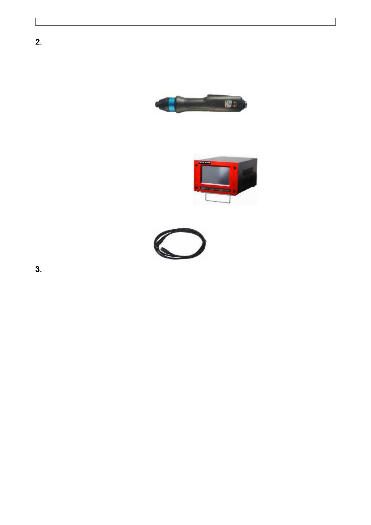
Screwdriver............................................................................................................................8
General specification ......................................................................................................8
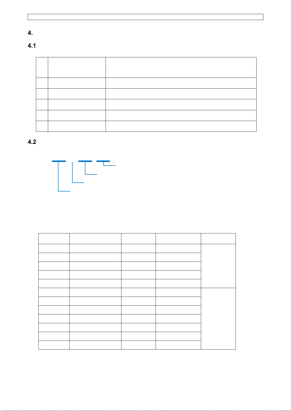
Model specification.........................................................................................................8
Auto Speed by torque setting under the each test condition..........................................11
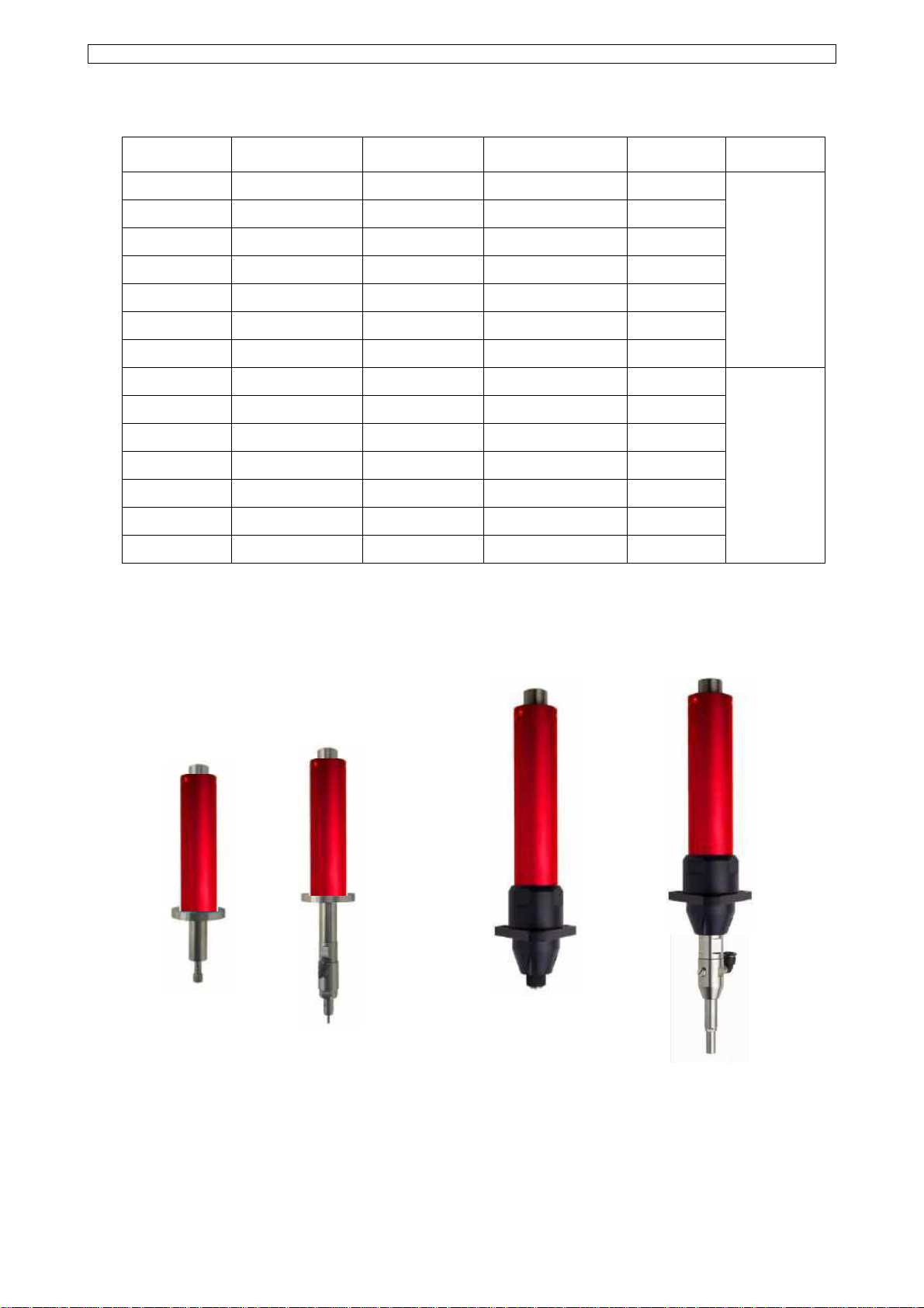
Screwdriver dimension..................................................................................................13
Screwdriver cables...............................................................................................................26
Models..........................................................................................................................26
Installation ....................................................................................................................27
Controller MDC v2 ...............................................................................................................28
Specification.................................................................................................................28
Model specification.......................................................................................................28
Controller dimension.....................................................................................................29
Operation.............................................................................................................................30
Getting started at first power on or after screwdriver change. .......................................30
Operation screen..........................................................................................................32
Rapid view Parameter screens.....................................................................................34
Presets or Model select ................................................................................................36
Parameters...................................................................................................................37
Fastening settings.........................................................................................................38
Advanced functions: .....................................................................................................41
7.7.1 Free reverse rotation before Fastening..................................................................41
7.7.2 Engaging Torque detection....................................................................................42
7.7.3 Angle after torque up .............................................................................................43
7.7.4 Thread tapping ......................................................................................................44
Multi Sequence settings................................................................................................45
Model settings...............................................................................................................46
Screw count settings.....................................................................................................48
Controller settings.........................................................................................................50
I/O settings ...................................................................................................................59
Network settings...........................................................................................................62
Monitoring.....................................................................................................................63
Remote control & Auto customizing..............................................................................65
Remote : Back up / Restore / Power Reset / Factory reset...........................................67
General Settings : Date / Storage / Options..................................................................68
General Settings : Barcode & Barcode Step.................................................................70
General Settings : SD memory card..............................................................................72
Firmware Upgrade...............................................................................................................73