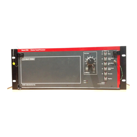
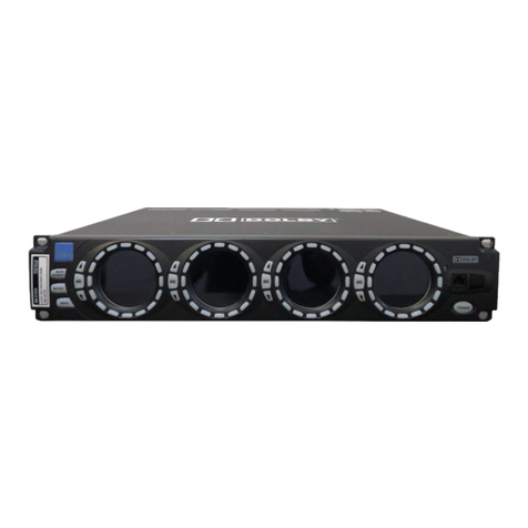
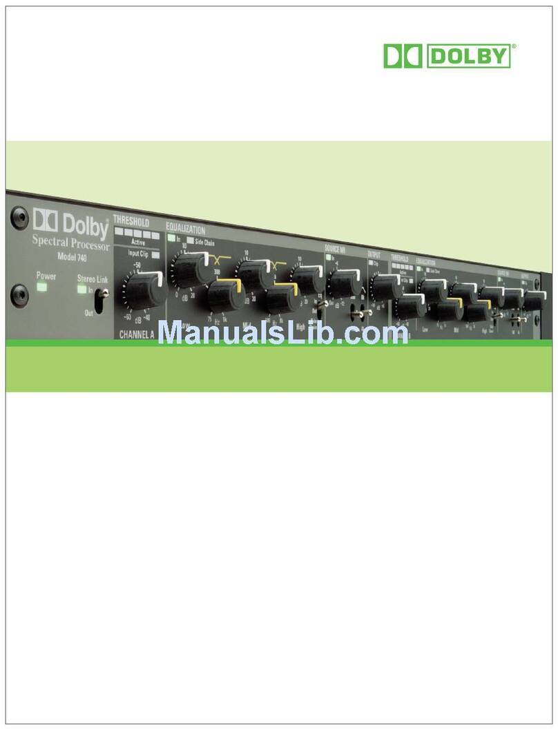
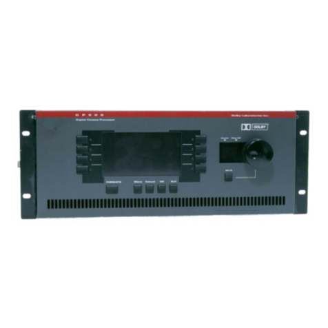
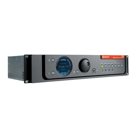
Dolby Laboratories CP650 User manual

Dolby
®
CP650
Digital Cinema Processor
Installation Manual
Issue 6 Part Number 91569

Dolby® CP650 Installation Manual
ii
Dolby Laboratories, Inc.
Corporate Headquarters
Dolby Laboratories, Inc.
100 Potrero Avenue
San Francisco, CA 94103-4813 USA
Telephone 415-558-0200
Fax 415-863-1373
www.dolby.com
European Headquarters
Dolby Laboratories, Inc.
Wootton Bassett
Wiltshire SN4 8QJ England
Telephone 44-1793-842100
Fax 44-1793-842101
DISCLAIMER OF WARRANTIES:
EQUIPMENT MANUFACTURED BY DOLBY LABORATORIES IS WARRANTED AGAINST DEFECTS IN
MATERIALS AND WORKMANSHIP FOR A PERIOD OF ONE YEAR FROM THE DATE OF PURCHASE.
THERE ARE NO OTHER EXPRESS OR IMPLIED WARRANTIES AND NO WARRANTY OF
MERCHANTABILITY OR FITNESS FOR A PARTICULAR PURPOSE, OR OF NONINFRINGEMENT OF
THIRD-PARTY RIGHTS (INCLUDING, BUT NOT LIMITED TO, COPYRIGHT AND PATENT RIGHTS).
LIMITATION OF LIABILITY:
IT IS UNDERSTOOD AND AGREED THAT DOLBY LABORATORIES’ LIABILITY, WHETHER IN
CONTRACT, IN TORT, UNDER ANY WARRANTY, IN NEGLIGENCE, OR OTHERWISE, SHALL NOT
EXCEED THE COST OF REPAIR OR REPLACEMENT OF THE DEFECTIVE COMPONENTS OR ACCUSED
INFRINGING DEVICES, AND UNDER NO CIRCUMSTANCES SHALL DOLBY LABORATORIES BE
LIABLE FOR INCIDENTAL, SPECIAL, DIRECT, INDIRECT, OR CONSEQUENTIAL DAMAGES,
(INCLUDING, BUT NOT LIMITED TO, DAMAGE TO SOFTWARE OR RECORDED AUDIO OR VISUAL
MATERIAL), COST OF DEFENSE, OR LOSS OF USE, REVENUE, OR PROFIT, EVEN IF DOLBY
LABORATORIES OR ITS AGENTS HAVE BEEN ADVISED, ORALLY OR IN WRITING, OF THE
POSSIBILITY OF SUCH DAMAGES.
Dolby, Pro Logic, and the double-D symbol are registered trademarks of Dolby Laboratories. Auditorium Assist, EQ Assist, and
Surround EX are trademarks of Dolby Laboratories. All other trademarks remain the property of their respective owners.
© 2008 Dolby Laboratories. All rights reserved.
Issue 6
Part No. 91569
S08/17479/19124

Dolby® CP650 Installation Manual
iii
Table of Contents
Regulatory Notices......................................................................................................................viii
CP650 Operating System Software History...............................................................................xi
Chapter 1 Introduction
1.1 Dolby Catalog Number Listing ................................................................1-2
1.2 List of Formats Available.........................................................................1-3
1.3 About Dolby Digital Surround EX...........................................................1-5
1.4 Specifications ...........................................................................................1-7
Chapter 2 Installation
2.1 Check Main Fuse......................................................................................2-1
2.2 Check Bypass Supply Mains Voltage Setting ..........................................2-2
2.3 Mount the CP650......................................................................................2-2
2.4 Mount the Auditorium Assist Microphone...............................................2-3
2.5 Connect the CP650 ...................................................................................2-3
2.5.1 Motor-Start Relays (Except CP650DC Models).........................2-4
2.5.2 Remote Controls .........................................................................2-4
2.5.3 Solar Cell Reader Boards (Except CP650DC Models)...............2-4
2.5.4 Analog Nonsync Sources............................................................2-8
2.5.5 Digital Audio Sources.................................................................2-8
2.5.6 Digital Audio Inputs—General Information.............................2-10
2.5.7 Exploded View and Board Locations .......................................2-12
2.5.8 Installation Wiring Diagrams....................................................2-12
Chapter 3 Front-Panel and Alignment Overview
3.1 The CP650 Front Panel ............................................................................3-1
3.2 The Setup Control Panel...........................................................................3-7
3.3 Power Supply Voltage Test Points ...........................................................3-9
Chapter 4 B-Chain Alignment
4.1 Check Theatre Equipment ........................................................................4-1
4.2 Microphone Placement.............................................................................4-2
4.3 Initial Setup ..............................................................................................4-3
4.4 Sound Pressure Level Calibration ............................................................4-4
4.4.1 Initial Setup with Cat. No. 791 Crossover Installed ...................4-4
4.4.2 Calibration Procedure—All CP650s...........................................4-4
4.5 Initial Output-Level Calibration ...............................................................4-6
4.5.1 Main Channels ............................................................................4-6
4.5.2 Subwoofer Channel.....................................................................4-7
4.6 Crossover Setup—CP650 with Cat. No. 791 ...........................................4-8
4.7 Room Equalization .................................................................................4-13

Dolby® CP650 Installation Manual
iv
4.7.1 Crossover Level Adjustment with Cat. No. 791 Crossover......4-13
4.7.2 Setting Coarse EQ.....................................................................4-14
4.7.3 Setting Fine EQ.........................................................................4-15
4.7.4 The EQ Assist Feature ..............................................................4-16
4.7.5 Setting Subwoofer Channel EQ ................................................4-17
4.7.6 Final Output-Level Calibration.................................................4-18
4.8 Final Sound Check—Rotating Pink Noise .............................................4-20
Chapter 5 A-Chain Alignment
5.1 Projector Checkup ....................................................................................5-2
5.2 Projector Analog Optical Alignment........................................................5-2
5.3 Dolby Level Set........................................................................................5-4
5.3.1 Automatic....................................................................................5-4
5.3.2 Manual ........................................................................................5-5
5.4 Film-Path Alignment Check.....................................................................5-6
5.5 Cell Alignment Check ..............................................................................5-6
5.6 Cell Wiring Check....................................................................................5-7
5.7 Azimuth Check.........................................................................................5-7
5.8 Focus Check .............................................................................................5-8
5.9 Optical HF Equalization (Slit-Loss EQ)...................................................5-9
5.9.1 Auto Slit-Loss EQ.......................................................................5-9
5.9.2 Manual Slit-Loss EQ...................................................................5-9
Chapter 6 Digital Soundheads
6.1 Mechanical Alignment .............................................................................6-1
6.2 Adjustment with Oscilloscope..................................................................6-2
6.3 Focus Adjustment.....................................................................................6-2
6.4 LED Brightness Confirmation and Adjustment .......................................6-3
6.4.1 Cat. No. 702 Reader....................................................................6-3
6.4.2 Cat. No. 701 Reader....................................................................6-4
6.4.3 Inboard Digital Readers ..............................................................6-4
Chapter 7 Final Adjustments
7.1 Setting Bypass Level ................................................................................7-1
7.2 Optical Surround Level Trim ...................................................................7-2
7.3 Setting Optical Surround Delay................................................................7-3
7.4 Setting Digital Surround Delay ................................................................7-4
7.5 Setting Dolby Digital Reader Delay.........................................................7-5
7.6 Dolby Digital Video Level Check............................................................7-7
7.7 Nonsync Level Adjustment ......................................................................7-7
7.8 Mono Level Trim .....................................................................................7-8
7.9 Mono EQ Adjustment...............................................................................7-8
7.10 Assigning Default Level and Global Delay to Front-Panel Buttons ........7-8

Dolby® CP650 Installation Manual
v
7.11 Assigning Front-Panel Buttons to Formats ..............................................7-9
7.12 Format 80/81 PCM Options .....................................................................7-9
7.13 Reversion Mode......................................................................................7-10
7.14 Auto Surround EX Disable.....................................................................7-10
7.15 Noise Gating...........................................................................................7-10
7.16 Running Auditorium Assist ....................................................................7-11
7.16.1 Establish Reference Measurements ..........................................7-12
7.16.2 Auditorium Sound Check..........................................................7-13
7.16.3 Fail Parameters..........................................................................7-13
7.16.4 Headroom Configuration ..........................................................7-14
7.17 Dialogue Normalization .........................................................................7-16
7.18 Network Configuration...........................................................................7-16
7.19 Clock Set ................................................................................................7-17
7.20 Date Set ..................................................................................................7-17
7.21 Mute Fade Time Adjustment..................................................................7-17
7.22 Auto Dolby Digital Function..................................................................7-18
Chapter 8 Accessories
8.1 Cat. No. 779 Remote Control Unit Installation........................................8-2
8.1.1 Remove the Housing...................................................................8-2
8.1.2 Make a Hole for the Interface Cable...........................................8-2
8.1.3 Connect to the Circuit Board ......................................................8-3
8.1.4 Set the Address Switch ...............................................................8-4
8.1.5 Assemble the Unit.......................................................................8-4
8.1.6 Connect to the CP650 .................................................................8-5
8.2 Cat. No. 771 Remote Fader Installation ...................................................8-6
Chapter 9 Maintenance and Troubleshooting
9.1 Print Cleanliness.......................................................................................9-1
9.2 Digital Soundhead Maintenance...............................................................9-1
9.3 CP650 Troubleshooting............................................................................9-2
9.3.1 Power Supply Voltage Ranges....................................................9-2
9.3.2 Exploded View and Board Locations .........................................9-3
9.3.3 The Event Log.............................................................................9-4
9.3.4 Troubleshooting Chart ................................................................9-4
Appendix A Software Operations..........................................................................................A-1
Appendix B Rear-Panel Connectors..................................................................................... B-1
Appendix C Format Descriptions.......................................................................................... C-1
Appendix D External Control................................................................................................D-1
Appendix E Setup and User’s Menus ................................................................................... E-1

Dolby® CP650 Installation Manual
vi
List of Figures
Figure 1-1 Surround Speaker/Amplifier Switching for 5.1-Channel Use....................................1-6
Figure 1-2 Surround Speaker/Amplifier Switching for Dolby Digital Surround EX Mode ........1-6
Figure 2-1 Fuse Locations on Earlier Units with External Fuses.................................................2-1
Figure 2-2 Fuse Locations on Units with Internal Fuses..............................................................2-1
Figure 2-3 Main Fuse Assembly—Earlier Units with External 6.3 A Fuses ...............................2-1
Figure 2-4 Star Washers and Rack-Mounting Screws..................................................................2-3
Figure 2-5 Cell Preamp Wiring Using Two Three-Conductor Shielded Cables..........................2-6
Figure 2-6 Cell Preamp Wiring Using One Five- or Six-Conductor Shielded Cable ..................2-6
Figure 2-7 Cell Preamp Wiring Using Two Two-Conductor Shielded Cable .............................2-7
Figure 2-8 Cell Preamp Wiring Using One Four-Conductor Shielded Cable..............................2-7
Figure 2-9 Cat. No. 790 S/PDIF Connections..............................................................................2-9
Figure 2-10 Cat. No. 794 AES/EBU and S/PDIF Jumper Selections and Connections...............2-9
Figure 2-11 Model CP650 Exploded View ................................................................................2-12
Installation Wiring Diagrams......................................................................................................2-13
Figure 3-1 Front-Panel Controls...................................................................................................3-1
Figure 3-2 Front-Panel Display Showing All Possible Channels Active.....................................3-2
Figure 3-3 Front-Panel Display Showing a Dolby Digital Film Playing .....................................3-3
Figure 3-4 Front-Panel Display Showing Dolby Digital Surround EX Film Playing..................3-3
Figure 3-5 Front-Panel Display when Running Earlier Software ................................................3-4
Figure 3-6 Fader Characteristic ....................................................................................................3-5
Figure 3-7 CP650 Operation and Setup Menu Control Buttons...................................................3-6
Figure 3-8 Setup Control Panel ....................................................................................................3-7
Figure 3-9 Power Supply Voltage Test Points .............................................................................3-9
Figure 4-1 EQ Microphone Placement.........................................................................................4-2
Figure 4-2 Oscilloscope Hookup..................................................................................................4-3
Figure 4-3 Switch to Setup Mode.................................................................................................4-3
Figure 4-4 Cat. No. 772B Board Jumpers for Cat. No. 791 Crossover........................................4-8
Figure 4-5 Cat. No. 791 Board Jumpers for Screen Loss HF Boost ............................................4-8
Figure 4-6 EQ Assist Operating Range ......................................................................................4-16
Figure 6-1 Digital Soundhead Adjustments .................................................................................6-1
Figure 6-2 Digital Video Oscilloscope Image—Focus Adjustment.............................................6-3
Figure 6-3 Measuring Peak Video Signal Voltage.......................................................................6-3
Figure 6-4 Cat. No. 702 LED Brightness Adjustment .................................................................6-3
Figure 6-5 Cat. No. 701 LED Brightness Adjustment .................................................................6-4
Figure 8-1 Cat. No. 779 Remote Control Functions ....................................................................8-2
Figure 8-2 Location to Drill Wiring Hole ....................................................................................8-3
Figure 8-3 Remote-Control Circuit-Board Connector..................................................................8-3
Figure 8-4 SW1 Address Switch Location...................................................................................8-4
Figure 8-5 Connection of Remotes to the CP650.........................................................................8-5
Figure 8-6 Cat. No. 771 Remote Fader ........................................................................................8-6
Figure 9-1 Digital/Analog Track Wear ........................................................................................9-1
Figure 9-2 Power Supply Voltage Test Points .............................................................................9-2
Figure 9-3 Model CP650 Exploded View ....................................................................................9-3

Dolby® CP650 Installation Manual
vii
List of Tables
Table 1-1 Formats Supported by the Various CP650 Models......................................................1-3
Table 2-1 Solar Cell Preamp Board Connectors ..........................................................................2-5
Table 2-2 Examples of Available Balanced ↔Unbalanced Adapters ......................................2-11
Table 7-1 Surround Delays Based on Theatre Dimensions (in Feet)...........................................7-5
Table 7-2 Surround Delays Based on Theatre Dimensions (in Meters).......................................7-5
Table 7-3 Typical Delay Settings for Penthouse Digital Film Readers .......................................7-6
Table 7-4 Typical Delay Settings for Other Digital Film Readers...............................................7-6
Table 9-1 Main Power Supply Voltage Ranges ...........................................................................9-2
Table 9-2 Bypass Power Supply Voltage Ranges ........................................................................9-2
Table B-1 Main Audio Output Connector Pinout .......................................................................B-1
Table B-2 Option Card I/O Connector Pinout with Cat. Nos. 790, 791, or 794 Installed ..........B-2
Table B-3 Option Card I/O Connector Pinout with Cat. No. 778 Installed ................................B-3
Table B-4 Dolby Digital Reader Input Connector Pinout ...........................................................B-4
Table B-5 Motor Start Connector Pinout ....................................................................................B-5
Table B-6 Optical Input Connector Pinout..................................................................................B-5
Table B-7 Mic Input Connector Pinout .......................................................................................B-5
Table B-8 Front-Panel Mic Multiplexer or EQ Mic Connector Pinout.......................................B-6
Table B-9 Remote Unit and Remote Fader Connector Pinout ....................................................B-6
Table B-10 Six-Channel Analog Audio In Connector Pinout.....................................................B-7
Table B-11 Automation I/O Connector Pinout............................................................................B-8
Table B-12 Automation I/O Connector Pins Used for Noise Gating..........................................B-9
Table B-13 Serial Data Connector Pinout ...................................................................................B-9
Table C-1 Channel Definitions....................................................................................................C-1
Table C-2 Format Characteristics Chart....................................................................................C-10
Table D-1 Remote Commands ....................................................................................................D-2
Table D-2 Remote Command Examples.....................................................................................D-3

Dolby® CP650 Installation Manual
viii
Regulatory Notices
FCC
NOTE: This equipment has been tested and found to comply with the limits for a
Class A digital device, pursuant to Part 15 of the FCC Rules. These limits are
designed to provide reasonable protection against harmful interference when the
equipment is operated in a commercial environment. This equipment generates, uses,
and can radiate radio frequency energy and, if not installed and used in accordance
with this instruction manual, may cause harmful interference to radio
communications. Operation of this equipment in a residential area is likely to cause
harmful interference in which case the user will be required to correct the interference
at his or her own expense.
Important Safety Instructions
1. Read these instructions.
2. Keep these instructions.
3. Heed all warnings.
4. Follow all instructions.
5. Do not use this apparatus near water.
6. WARNING: To reduce the risk of fire or electric shock, do not expose this
apparatus to rain or moisture.
7. Clean only with dry cloth.
8. Do not install near any heat sources such as radiators, heat registers, stoves, or
other apparatus (including amplifiers) that produce heat.
9. No naked flame sources, such as lighted candles, should be placed on the
apparatus.
10. Protect the power cord from being walked on or pinched, particularly at plugs,
convenience receptacles, and the point where they exit from the apparatus.
11. Only use attachments/accessories specified by the manufacturer.
12. Unplug this apparatus when unused for long periods of time.
13. Refer all servicing to qualified service personnel. Servicing is required when the
apparatus has been damaged in any way, such as the power-supply cord or plug is
damaged, liquid has been spilled or objects have fallen into the apparatus, the
apparatus has been exposed to rain or moisture, does not operate normally, or has
been dropped.

Dolby® CP650 Installation Manual
ix
14. Do not expose the apparatus to dripping or splashing and no objects filled with
liquids, such as vases, shall be placed on the apparatus.
15. CAUTION: Troubleshooting must be performed by a trained technician. To
reduce the risk of electric shock, do not attempt to service this equipment unless
you are qualified to do so.
16. Do not defeat the safety purpose of the polarized or grounding-type plug. A
polarized plug has two blades with one wider than the other. A grounding type
plug has two blades and a third grounding prong. The wide blade or the third
prong is provided for your safety. If the provided plug does not fit into your
outlet, consult an electrician for replacement of the obsolete outlet.
17. This apparatus must be earthed (grounded) by connecting to a correctly wired and
earthed power outlet.
18. Ensure that your mains supply is in the correct range for the input power
requirement of the unit.
19. In order to reduce the risk of electrical shock, the power cord must be
disconnected when the power supply assembly is removed.
20. The mains power disconnect device for this unit is the plug-in mains cord rather
than a power switch. The mains cord must remain readily accessible for
disconnecting mains power.
21. This equipment is designed to mount in a suitably ventilated 19” rack. Ensure that
any ventilation slots in the unit are not blocked or covered.
22. To avoid exposure to dangerous voltages and to avoid damage to the unit, do not
connect the or rear-panel Ethernet port to telephone circuits.
23. As the colours of the cores in the mains lead may not correspond with the
coloured markings identifying the terminals in your plug, proceed as follows:
•The core that is coloured green or green and yellow must be connected to the terminal in the
plug identified by the letter Eor by the earth symbol or coloured green.
•The core that is coloured blue must be connected to the terminal that is marked with the letter
Nor coloured black.
•The core that is coloured brown must be connected to the terminal that is marked with the
letter Lor coloured red.
This apparatus must be earthed.
Canada
This Class A digital apparatus complies with Canadian ICES-003.

Dolby® CP650 Installation Manual
x
This equipment complies with the EMC requirements of EN55103-1 and EN55103-2 when operated in an E2
environment in accordance with this manual.
IMPORTANT SAFETY NOTICE
This unit complies with the safety standard EN60065. The unit shall not be exposed to dripping or splashing and no objects filled with liquids,
such as coffee cups, shall be placed on the equipment. To ensure safe operation and to guard against potential shock hazard or risk of fire, the
following must be observed:
o Ensure that your mains supply is in the correct range for the input power requirement of the unit.
o Ensure fuses fitted are the correct rating and type as marked on the unit.
o The unit must be earthed by connecting to a correctly wired and earthed power outlet.
o The power cord supplied with this unit must be wired as follows:
Live—Brown Neutral—Blue Earth—Green/Yellow
IMPORTANT – NOTE DE SECURITE
Ce materiel est conforme à la norme EN60065. Ne pas exposer cet appareil aux éclaboussures ou aux gouttes de liquide. Ne pas poser d'objets
remplis de liquide, tels que des tasses de café, sur l'appareil. Pour vous assurer d'un fonctionnement sans danger et de prévenir
tout choc électrique ou tout risque d'incendie, veillez à observer les recommandations suivantes:
o Le selecteur de tension doit être placé sur la valeur correspondante à votre alimentation réseau.
o Les fusibles doivent correspondre à la valeur indiquée sur le materiel.
o Le materiel doit être correctement relié à la terre.
o Le cordon secteur livré avec le materiel doit être cablé de la manière suivante:
Phase—Brun Neutre—Bleu Terre—Vert/Jaune
WICHTIGER SICHERHEITSHINWEIS
Dieses Gerät entspricht der Sicherheitsnorm EN60065. Das Gerät darf nicht mit Flüssigkeiten (Spritzwasser usw.) in Berührung kommen; stellen
Sie keine Gefäße, z.B. Kaffeetassen, auf das Gerät. Für das sichere Funktionieren des Gerätes und zur Unfallverhütung (elektrischer Schlag,
Feuer) sind die folgenden Regeln unbedingt einzuhalten:
o Der Spannungswähler muß auf Ihre Netzspannung eingestellt sein.
o Die Sicherungen müssen in Typ und Stromwert mit den Angaben auf dem Gerät übereinstimmen.
o Die Erdung des Gerätes muß über eine geerdete Steckdose gewährleistet sein.
o Das mitgelieferte Netzkabel muß wie folgt verdrahtet werden:
Phase—braun Nulleiter—blau Erde—grün/gelb
NORME DI SICUREZZA – IMPORTANTE
Questa apparecchiatura è stata costruita in accordo alle norme di sicurezza EN60065. Il prodotto non deve essere sottoposto a schizzi, spruzzi e
gocciolamenti, e nessun tipo di oggetto riempito con liquidi, come ad esempio tazze di caffè, deve essere appoggiato sul dispositivo. Per una
perfetta sicurezza ed al fine di evitare eventuali rischi di scossa êlettrica o d'incendio vanno osservate le seguenti misure di sicurezza:
o Assicurarsi che il selettore di cambio tensione sia posizionato sul valore corretto.
o Assicurarsi che la portata ed il tipo di fusibili siano quelli prescritti dalla casa costruttrice.
o L'apparecchiatura deve avere un collegamento di messa a terra ben eseguito; anche la connessione rete deve
avere un collegamento a terra.
o Il cavo di alimentazione a corredo dell'apparecchiatura deve essere collegato come segue:
Filo tensione—Marrone Neutro—Blu Massa—Verde/Giallo
AVISO IMPORTANTE DE SEGURIDAD
Esta unidad cumple con la norma de seguridad EN60065. La unidad no debe ser expuesta a goteos o salpicaduras y no deben colocarse sobre el
equipo recipientes con liquidos, como tazas de cafe. Para asegurarse un funcionamiento seguro y prevenir cualquier posible peligro de descarga o
riesgo de incendio, se han de observar las siguientes precauciones:
o Asegúrese que el selector de tensión esté ajustado a la tensión correcta para su alimentación.
o Asegúrese que los fusibles colocados son del tipo y valor correctos, tal como se marca en la unidad.
o La unidad debe ser puesta a tierra, conectándola a un conector de red correctamente cableado y puesto a tierra.
o El cable de red suministrado con esta unidad, debe ser cableado como sigue:
Vivo—Marrón Neutro—Azul Tierra—Verde/Amarillo
VIKTIGA SÄKERHETSÅTGÄRDER!
Denna enhet uppfyller säkerhetsstandard EN60065. Enheten får ej utsättas för yttre åverkan samt föremål innehållande vätska, såsom
kaffemuggar, får ej placeras på utrustningen." För att garantera säkerheten och gardera mot eventuell elchock eller brandrisk, måste följande
observeras:
o Kontrollera att spänningsväljaren är inställd på korrekt nätspänning.
o Konrollera att säkringarna är av rätt typ och för rätt strömstyrka så som anvisningarna på enheten föreskriver.
o Enheten måste vara jordad genom anslutning till ett korrekt kopplat och jordat el-uttag.
o El-sladden som medföljer denna enhet måste kopplas enligt foljande:
Fas—Brun Neutral—Blå Jord—Grön/Gul
BELANGRIJK VEILIGHEIDS-VOORSCHRIFT:
Deze unit voldoet aan de EN60065 veiligheids-standaards. Dit apparaat mag niet worden blootgesteld aan vocht. Vanwege het risico dat er
druppels in het apparaat vallen, dient u er geen vloeistoffen in bekers op te plaatsen. Voor een veilig gebruik en om het gevaar van electrische
schokken en het risico van brand te vermijden, dienen de volgende regels in acht te worden genomen:
o Controleer of de spanningscaroussel op het juiste Voltage staat.
o Gebruik alleen zekeringen van de aangegeven typen en waarden.
o Aansluiting van de unit alleen aan een geaarde wandcontactdoos.
o De netkabel die met de unit wordt geleverd, moet als volgt worden aangesloten:
Fase—Bruin Nul—Blauw Aarde—Groen/Geel
PRODUCT END-OF-LIFE INFORMATION
This product has been designed and built by Dolby Laboratories to give many years of service, and is backed by our
commitment to provide high-quality support. When it eventually reaches the end of its serviceable life, it should be
disposed of in accordance with local or national legislation.
For current information, please visit our website: www.dolby.com/environment.
F
E
NL
S
I
D
GB
Dolby®CP650 Installation Manual
xi
CP650 Operating System Software History
V.1.0.4.4
•First product shipments.
•Covered in installation manual, Issue 1.
V.1.1.3.0
•Added support for Cat. No. 790 or 794 card: Dolby®Digital Surround EXTM
decoder and AES3 input for stereo pulse-code modulated (PCM) or Dolby Digital
bitstreams from consumer products.
•Covered in installation manual addendum, Part No. 91743.
V.1.1.5.0
•Added support for Cat. No. 779 remote control unit and Cat. No. 771 remote fader
unit. Covered in Remotes Installation Manual, Part No. 91733.
V.1.1.7.0
•Added support for formats 92 and 93, Dolby SR input selections.
V.1.2.x.y (where x and y may be any numbers)
•Added support for auto Dolby Digital Surround EX switching, external control
via the RS-232 serial data port, and the rotating pink-noise feature.
•The EQ AssistTM feature description was added to the installation manual.
•These features, along with all of the above updates, are covered in installation
manual Issue 2.
V.2.0.x.y (where x and y may be any numbers)
•Added the Auditorium AssistTM feature, which measures and stores a
characterization of the audio environment in a theatre, and allows periodic checks
and comparisons to qualify the sound system.
•Added support for the Cat. No. 778 Eight-Channel Digital I/O Card.
•Added a noise floor optimization feature, which provides automatic gain
adjustments in the equalizers for improved noise performance.
•These features, plus all of the above updates, are covered in installation manual
Issue 3.

Dolby®CP650 Installation Manual
xii
V2.1.x.y (where x and y may be any numbers)
•Added support for the Cat. No. 790 Dolby Digital Surround EX Decoder Card
with four S/PDIF digital inputs. This card replaces the Cat. No. 794, adding three
additional S/PDIF digital inputs.
•Added support for the Cat. No. 791 Digital Crossover Card. This card plugs into
the Cat. No. 790, providing two- and three-way screen channel crossover
capability along with support for Left Extra/Right Extra screen channels.
V2.2.x.y (where x and y may be any numbers)
•Digital film reader output levels can now be checked using the CP650 front-panel
screen or setup software.
•The noise floor optimization setup step is now called headroom configuration.
•The default format assigned to the front-panel User 1 button (U1) is now
format 75, Nonsync 1 Dolby Pro Logic®with Subwoofer.
•The test point signal that feeds an external real-time analyzer has been enabled to
assist in setting the bypass output.
•Support for Ethernet-based ASCII control and network support has been added.
•Support for subtitling has been added.
•Expanded support for the Cat. No. 778 Digital Input/Ouput Card is incorporated
including unity-gain functionality.
V2.3.4.x (where x may be any number)
•Formats for front-panel buttons 01, 04, and 11 are now user-assignable along with
buttons U1, U2, and NS.
•Added format 76, Nonsync 2 Pro Logic with Subwoofer.
•Added global audio delay setting for use in Dolby Digital Cinema systems.
•Improved the communications interface to the Cat. No. 771 Remote Fader and
779 Remote Control Unit.
•Improved response to digital audio input streams.
V2.3.5.x (where x may be any number)
•Assigned default network address to be compatible with Dolby Digital Cinema.
V2.3.6.x (where x may be any number)
•All front-panel format buttons are user-assignable on CP650DC models
•Film-related functions are not active on CP650DC models

Dolby®CP650 Installation Manual
1-1
Chapter 1
Introduction
The Dolby®CP650 Digital Cinema Processor is a self-contained, all-digital cinema
processor capable of supporting Dolby Digital Cinema systems, as well as Dolby
Digital, Dolby Digital Surround EXTM, Dolby SR, Dolby A-type, and Academy mono
film sound playback.
For digital cinema installations that do not require film soundtrack playback, the
CP650DC versions provide digital audio inputs for connection to a digital cinema
server, while removing the additional cost of 35 mm film sound support.
The CP650 provides inputs for two projector soundheads (both analog and digital), an
external six-channel processor, two nonsync sources, and a PA microphone. Its audio
outputs are balanced, with a multipin connector configured to the THX standard. A
built-in Ethernet and a serial interface accommodate PC control and cinema network
connectivity.
Installation is simplified by built-in test instrumentation that includes a real-time
analyzer. Third-octave equalization, plus bass and treble trim controls, are provided
for up to seven channels (Left, Center, Right, Left Surround, Right Surround, Back
Surround Left, and Back Surround Right). A digital parametric equalizer is provided
for subwoofer equalization.
Easily programmed internal software manages most existing or likely future formats.
While an external PC is not required for setup, a full-featured software package is
available in several languages to facilitate the setup process. A serial connector for a
PC, an input for a calibration microphone multiplexer, and a variety of test points are
all accessible behind an access door on the front panel. Built-in diagnostic software
runs automatically whenever the CP650 is turned on.
Calibration settings for a given theatre can be stored on a PC, and, if desired,
transferred directly to another CP650, minimizing the need for additional calibration
after repairs. As improvements to the CP650 digital control and processing software
are developed, the latest revisions are transferable from a PC to the CP650.
Options available for the CP650 include a remote fader (Cat. No. 771), a remote unit
(Cat. No. 779) that duplicates many of the CP650’s front-panel controls, and a ten-
channel digital I/O card (Cat. No. 778).

Dolby®CP650 Installation Manual Introduction
1-2
1.1 Dolby Catalog Number Listing
Cat. No. 771 Remote Fader
Cat. No. 772B Analog I/O and Bypass Circuit Board
Cat. No. 773 Dolby Digital Film Decoder Circuit Board
Cat. No. 774A System Controller Circuit Board
Cat. No. 775 Backplane Board
Cat. No. 775DC Backplane Board (used on CP650DC models)
Cat. No. 776 Power Supply Assembly
Cat. No. 776DC Power Supply Assembly (used on CP650DC models)
Cat. No. 777 Front-Panel Circuit Board
Cat. No. 778 Digital I/O Board provides up to ten channels of digital I/O
Cat. No. 779 Remote Control Unit
Cat. No. 790 Digital Input/Dolby Digital Surround EX Decoder Card
(replaces the earlier Cat. No. 794)
Cat. No. 791 Crossover Card (Cat. Nos. 790, 772A or B, and 774A required)
Cat. No. 795 Power Supply Snubber Board
Cat. No. 792 Bypass Power Regulator Circuit Board (not used on CP650DC
models)
Cat. No. 794 Dolby Digital Surround EX Decoder Card (with digital AES3
input; used in earlier CP650s and replaced by the Cat. No. 790)
Cat. No. 797 Flash Memory Module (part of the Cat. No. 774A board)

Dolby®CP650 Installation Manual Introduction
1-3
1.2 List of Formats Available
The formats supported by each CP650 model are listed in Table 1-1. See Appendix C for a complete definition of each format.
Table 1-1 Formats Supported by the Various CP650 Models
Format Description CP650SR CP650D
Cat. No. 773 CP650
Cat. No.790 CP650XO
Cat. No. 790
Cat. No. 791
CP650DC
Cat. No. 790 CP650DCXO
Cat. No. 790
Cat. No. 791
CP650DCD
Cat. No. 778
01 Academy mono optical film X X X X
04 Dolby A-type optical film X X X X
05 Dolby SR optical film X X X X
10 Dolby Digital film X X X
11 External six-channel analog in X X X X X X X
13 Dolby Digital Surround EX film X X X
20 35 mm magnetic film, L, C, R three-channel X X X X X X X
22 35 mm magnetic film, four-channel X X X X X X X
42 70 mm Dolby A-type mag film X X X X X X X
60 Nonsync 1, L, R, Surrounds X X X X X X X
61 Nonsync 2, L, R, Surrounds X X X X X X X
64 Public Address Center channel X X X X X X X
65 Public Address Ls, Rs Surrounds X X X X X X X
66 Test Tone 320 Hz All Channels X X X X X X X
70 Nonsync 1 Mono Center, Surrounds X X X X X X X
71 Nonsync 1 Mono Center X X X X X X X
73 Nonsync 1 Pro Logic®Left-Center-Right X X X X X X X
74 Nonsync 1 Pro Logic No Subwoofer X X X X X X X
75 Nonsync 1 Pro Logic With Subwoofer X X X X X X X
76 Nonsync 2 Pro Logic With Subwoofer X X X X X X X
80 Bitstream Master Digital In X X X X X
81 Bitstream Master Digital In w/Surround EX X X X X X

Dolby®CP650 Installation Manual Introduction
1-4
Format Description CP650SR CP650D
Cat. No. 773 CP650
Cat. No.790 CP650XO
Cat. No. 790
Cat. No. 791
CP650DC
Cat. No. 790 CP650DCXO
Cat. No. 790
Cat. No. 791
CP650DCD
Cat. No. 778
85 Bitstream PCM Eight-Channel Input,
Ten-Channel Output (Le/Re Support)
X X X
86 Bitstream PCM Eight-Channel Input,
Ten-Channel Output w/Surround EX
(Le/Re Support)
X X X
87 External Six-Channel analog in
w/Surround EX
X X X X X
88 Six-Channel PCM, L/R, C/SW, Ls/Rs X X X X X
89 Six-Channel PCM w/Surround EX on Ls/Rs X X X X X
90 Seven-Channel PCM, L/R, C/LFE, Ls/Rs, Bs X X X X X
92 Dolby SR, input from Six-Channel L/R pair X X X X X X X
93 Dolby SR, input from NS1 L/R X X X X X X X

Dolby®CP650 Installation Manual Introduction
1-5
1.3 About Dolby Digital Surround EX
Dolby Digital Surround EX adds a third surround channel to digital film sound, a
concept first envisioned by sound designers at Lucasfilm’s Skywalker Sound
postproduction facility. It gives sound mixers a new level of creative freedom.
Dolby Digital Surround EX is fully compatible with all current 5.1 digital sound
formats and theatre systems. Prints that use it play normally with current systems, and
provide the extra surround channel when played using a CP650 cinema processor
equipped with a Cat. No. 790 or 794 board.
A Center screen channel is necessary to ensure the precise localization of front
sounds for all viewers, including those seated off to the sides. Dolby Digital
Surround EX brings similar benefits to the surround sound field. With Surround EX,
a Back Surround channel is reproduced by the speaker array at the back of the theatre,
while Left Surround and Right Surround channels are reproduced by the side arrays.
This means that sounds can now be positioned behind the audience, allowing for
exciting new effects, such as true 360-degree pans.
The Back Surround channel also makes front-to-back and back-to-front transitions
more realistic. Flyovers really seem to pass overhead, rather than down the sides of
the theatre. Even ambient sound reproduction is improved, being less affected by the
width of the theatre. Equally important, the new Back Surround channel ensures that
even viewers seated close to the left or right of the theatre experience the total
surround ambience intended by the filmmaker.
The UEX650 kit upgrades the CP650D 5.1-channel processor to include three
surround channels that can play digital prints prepared with the Dolby Digital
Surround EX process. The installation requires wiring the surround speakers into left,
back (split into two groups), and right. Two power amplifier channels are required for
powering the two groups of Back Surround channel speakers. Figure 1-1 shows the
surround signal distribution for conventional 5.1-channel surround. Distribution for
the Dolby Digital Surround EX format is shown in Figure 1-2.
Auto Surround EX
Dolby Digital bitstreams that contain a data bit signifying Surround EX encoding
cause the CP650 to automatically switch to Dolby Digital Surround EX decoding.

Dolby®CP650 Installation Manual Introduction
1-6
Left surround
Back surround left
Right surround
Back surround right
Dolby Digital
5.1 mode
Surround
amplifiers
Dolby CP650
Ls
Bsl
Bsr
10
Rs
Ls
Rs
Ls
Bsl
Bsr
Rs
Figure 1-1 Surround Speaker/Amplifier Switching for 5.1-Channel Use
Left surround
Back surround left
Right surround
Back surround right
Dolby Digital
Surround EX mode
Surround
amplifiers
Dolby CP650
Ls
Bsl
Bsr
U1
Rs
Ls
Rs
Ls
Bsl
Bsr
Rs
Bs
Figure 1-2 Surround Speaker/Amplifier Switching for Dolby Digital Surround EX Mode

Dolby®CP650 Installation Manual Introduction
1-7
1.4 Specifications
For digital cinema installations that do not require film soundtrack playback, the
CP650DC versions provide digital audio inputs only.
Signal Inputs
Optical: Balanced inputs for two projectors with stereo solar cells or analog LED
readers, digitally controlled gain and digital slit-loss EQ, power available for external
cell preamp circuits; 9-pin D-connectors
Digital film reader: Inputs for two Dolby digital soundheads; 25-pin D-connectors
Nonsync: Two stereo inputs, 21 kΩ, sensitivity: 0.2–4 V (NS 1),
0.06–1.5 V (NS 2); RCA-type phono connectors
Six-channel analog input: For external digital processor, 10 kΩ(L, R),
27 kΩ(C, Ls, Rs, SW), 300 mV operating level; 25-pin D-connector
Microphone: Balanced input for Auditorium AssistTM microphone, PA mic, or B-chain
alignment mic (or multiplexer), 15 V phantom power switchable via front-panel DIP
switch; rear-panel XLR and front-panel 9-pin D-connector
AES/EBU digital inputs: Accommodate stereo PCM audio at 48, 44.1, or 32 kHz,
also accept Dolby Digital bitstreams; input via 25-pin D-connector with optional
adapter boards (Cat. No. 790 or 778)
110Ω±20%, balanced (equipped with Cat. No. 778, four inputs), or
75Ω±20%, single-ended (equipped with Cat. No. 790, four inputs)
Signal Outputs
Balanced, output impedance: 100Ω(load >600Ω)
Max level: +26 dBu (15.5 V), balanced loads; +20 dBu (7.75 V), unbalanced loads
Dolby level output adjust range: –31 to 0 dBu (20–780 mV)
Other Connections
Cat. No. 779 remote control unit and Cat. No. 771 remote fader connector (terminals
for stripped wires)
Connectors (front and rear) for external PC control and setup, RS-232C
(9-pin D-connector)
Hearing-impaired output: Center-weighted sum of L, R, and C; output
impedance 100Ω, output level 200 mV fixed; unbalanced (RCA-type phono
connector)
Automation connector for controlling and indicating format, fader select, and mute;
interface similar to Model CP65
Connector for Ethernet link, RJ-45
Dolby Decoding
5.1 channels: Dolby Digital and Dolby Digital Surround EX
Four channels: Dolby A-type
Two channels: Dolby SR
Dolby Pro Logic

Other manuals for CP650
8
Table of contents
Other Dolby Laboratories Computer Hardware manuals

Dolby Laboratories
Dolby Laboratories CAT862 User manual

Dolby Laboratories
Dolby Laboratories CP45 User manual

Dolby Laboratories
Dolby Laboratories Lake LP4D4 User manual

Dolby Laboratories
Dolby Laboratories DA20 User manual

Dolby Laboratories
Dolby Laboratories CP500-D User manual

Dolby Laboratories
Dolby Laboratories CP650 User manual

Dolby Laboratories
Dolby Laboratories CP750 User manual

Dolby Laboratories
Dolby Laboratories Spectral Processor 740 User manual

Dolby Laboratories
Dolby Laboratories Lake LPD User manual

Dolby Laboratories
Dolby Laboratories CP500 User manual