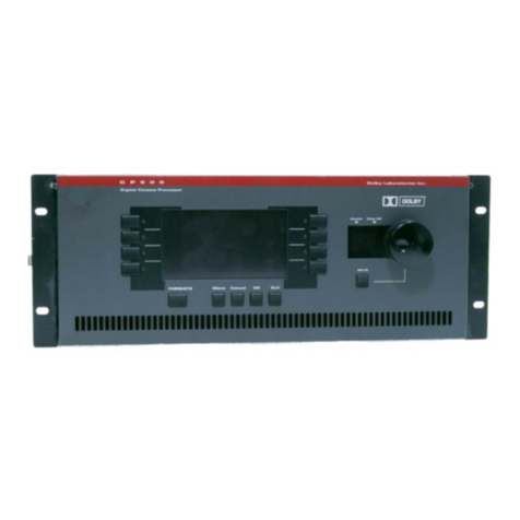
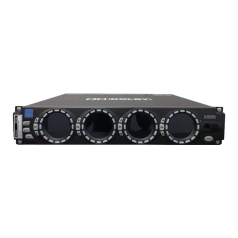
Dolby Laboratories CP750 User manual

Dolby CP750 Digital
Cinema Processor
Manual
Issue 5 Part Number 9110270
®

ii Dolby®CP750 Digital Cinema Processor Manual
Dolby Laboratories, Inc.
Corporate Headquarters
DolbyLaboratories,Inc.
100PotreroAvenue
SanFrancisco,CA 94103‐4813 USA
Telephone415‐558‐0200
Fax415‐863‐1373
www.dolby.com
European Headquarters
DolbyLaboratories,Inc.
WoottonBassett
Wiltshire SN48QJ England
Telephone44‐1793‐842100
Fax44‐1793‐842101
DISCLAIMEROFWARRANTIES:
EQUIPMENTMANUFACTUREDBYDOLBYLABORATORIESISWARRANTEDAGAINSTDEFECTS
INMATERIALSANDWORKMANSHIPFORAPERIODOFONEYEARFROMTHEDATEOF
PURCHASE.THEREARENOOTHEREXPRESSORIMPLIEDWARRANTIESANDNOWARRANTY
OFMERCHANTABILITYORFITNESSFORAPARTICULARPURPOSE,OROFNONINFRINGEMENT
OFTHIRD‐PARTYRIGHTS(INCLUDING,BUTNOTLIMITEDTO,COPYRIGHTANDPATENT
RIGHTS).
LIMITATIONOFLIABILITY:
ITISUNDERSTOODANDAGREEDTHATDOLBYLABORATORIES’LIABILITY,WHETHERIN
CONTRACT,INTORT,UNDERANYWARRANTY,INNEGLIGENCE,OROTHERWISE,SHALLNOT
EXCEEDTHECOSTOFREPAIRORREPLACEMENTOFTHEDEFECTIVECOMPONENTSOR
ACCUSEDINFRINGINGDEVICES,ANDUNDERNOCIRCUMSTANCESSHALLDOLBY
LABORATORIESBELIABLEFORINCIDENTAL,SPECIAL,DIRECT,INDIRECT,OR
CONSEQUENTIALDAMAGES(INCLUDING,BUTNOTLIMITEDTO,DAMAGETOSOFTWAREOR
RECORDEDAUDIOORVISUALMATERIAL),COSTOFDEFENSE,ORLOSSOFUSE,REVENUE,OR
PROFIT,EVENIFDOLBYLABORATORIESORITSAGENTSHAVEBEENADVISED,ORALLYORIN
WRITING,OFTHEPOSSIBILITYOFSUCHDAMAGES.
.
Dolby,ProLogic,andthedouble‐DsymbolareregisteredtrademarksofDolbyLaboratories.SurroundEX
isatrademarkofDolbyLaboratories.Allothertrademarksremainthepropertyoftheirrespectiveowners.
©2011DolbyLaboratories.Allrightsreserved.
PartNumber9110270
Issue5
S11/21444/24795

Dolby®CP750 Digital Cinema Processor Manual iii
Regulatory Notices
FCC
NOTE:ThisequipmenthasbeentestedandfoundtocomplywiththelimitsforaClassA
digitaldevice,pursuanttoPart15oftheFCCRules.Theselimitsaredesignedtoprovide
reasonableprotectionagainstharmfulinterferencewhentheequipmentisoperatedina
commercialenvironment.Thisequipmentgenerates,uses,andcanradiateradiofrequency
energyand,ifnotinstalledandusedinaccordancewiththisinstructionmanual,maycause
harmfulinterferencetoradiocommunications.Operationofthisequipmentinaresidential
areaislikelytocauseharmfulinterferenceinwhichcasetheuserwillberequiredtocorrect
theinterferenceathisownexpense.
Canada
ThisClassAdigitalapparatuscomplieswithCanadianICES‐003.
EU/EMC
ThisunitcomplieswiththeEMCrequirementofEN55103‐1andEN55103‐2whenoperated
inanE2environmentinaccordancewiththismanual.
Important Safety Instructions
1. Readtheseinstructions.
2. Keeptheseinstructions.
3. Heedallwarnings.
4. Followallinstructions.
5. Donotusethisapparatusnearwater.
6. WARNING:Toreducetheriskoffireorelectricshock,donotexposethisapparatusto
rainormoisture.
7. Cleanonlywithdrycloth.
8. Donotinstallnearanyheatsourcessuchasradiators,heatregisters,stoves,orother
apparatus(includingamplifiers)thatproduceheat.
9. Nonakedflamesources,suchaslightedcandles,shouldbeplacedontheapparatus
10. Protectthepowercordfrombeingwalkedonorpinchedparticularlyatplugs,
conveniencereceptacles,andthepointwheretheyexitfromtheapparatus.
11. Onlyuseattachments/accessoriesspecifiedbythemanufacturer.
12. Unplugthisapparatuswhenunusedforlongperiodsoftime.
13. Referallservicingtoqualifiedservicepersonnel.Servicingisrequiredwhenthe
apparatushasbeendamagedinanyway,suchaspower‐supplycordorplugis
damaged,liquidhasbeenspilledorobjectshavefallenintotheapparatus,the
apparatushasbeenexposedtorainormoisture,doesnotoperatenormally,orhas
beendropped.
14. Donotexposetheapparatustodrippingorsplashingandnoobjectsfilledwith
liquids,suchasvases,shallbeplacedontheapparatus.

iv Dolby®CP750 Digital Cinema Processor Manual
Regulatory Notices
15. CAUTION:Troubleshootingmustbeperformedbyatrainedtechnician.Toreducethe
riskofelectricshock,donotattempttoservicethisequipmentunlessyouare
qualifiedtodoso.
16. Donotdefeatthesafetypurposeofthepolarizedorgrounding‐typeplug.Apolarized
plughastwobladeswithonewiderthantheother.Agrounding‐typeplughastwo
bladesandathirdgroundingprong.Thewidebladeorthethirdprongisprovided
foryoursafety.Iftheprovidedplugdoesnotfitintoyouroutlet,consultanelectrician
forreplacementoftheobsoleteoutlet.
17. Thisapparatusmustbeearthed(grounded)byconnectingtoacorrectlywiredand
earthedpoweroutlet.
18. Ensurethatyourmainssupplyisinthecorrectrangefortheinputpowerrequirement
oftheunit.
19. Inordertoreducetheriskofelectricalshock,thepowercordmustbedisconnected
whenthepowersupplyassemblyisremoved.
20. Thisequipmentisdesignedtomountinasuitablyventilated19”rack;ensurethatany
ventilationslotsintheunitarenotblockedorcovered.
21. Themainspowerdisconnectdeviceforthisunitistheplug‐inmainscordratherthan
apowerswitch.Themainscordmustremainreadilyaccessiblefordisconnecting
mainspower.
22. Toavoidexposuretodangerousvoltagesandtoavoiddamagetotheunit,donot
connecttherear‐panelEthernetporttotelephonecircuits.
23. Asthecolorsofthecoresinthemainsleadmaynotcorrespondwiththecolored
markingsidentifyingtheterminalsinyourplug,proceedasfollows:
•Thegreenandyellowcoremustbeconnectedtotheterminalintheplug
identifiedbytheletterE,orbytheearthsymbol,orcoloredgreen,orgreen
andyellow.
•ThebluecoremustbeconnectedtotheterminalmarkedwiththeletterNor
coloredblack.
•ThebrowncoremustbeconnectedtotheterminalmarkedwiththeletterLor
coloredred.
24. Thisapparatusmustbeearthed.
Fuses
WEEE
PRODUCTEND‐OF‐LIFEINFORMATION
Warning: Checkthatthecorrectfuseshavebeeninstalled.Forcontinuedprotectionagainst
riskoffire,replaceonlywithfusesofthesametypeandrating.
ThisproductwasdesignedandbuiltbyDolbyLaboratoriestoprovidemanyyearsof
service,andisbackedbyourcommitmenttoprovidehigh‐qualitysupport.Whenit
eventuallyreachestheendofitsserviceablelife,itshouldbedisposedofinaccordance
withlocalornationallegislation.
Forcurrentinformationpleasevisitourwebsiteat:http://www.dolby.com/environment

Regulatory Notices
Dolby®CP750 Digital Cinema Processor Manual v
IMPORTANTSAFETYNOTICE
ThisunitcomplieswithsafetystandardEN60065asappropriate.Theunitshallnotbeexposedtodrippingorsplashingandnoobjectsfilledwithliquids,suchas
coffeecups,shallbeplacedontheequipment.Toensuresafeoperationandtoguardagainstpotentialshockhazardorriskoffire,thefollowingmustbe
observed:
oEnsurethatyourmainssupplyisinthecorrectrangefortheinputpowerrequirementoftheunit.
oEnsurefusesfittedarethecorrectratingandtypeasmarkedontheunit.
oTheunitmustbeearthedbyconnectingtoacorrectlywiredandearthedpoweroutlet.
oThepowercordsuppliedwiththisunitmustbewiredasfollows:
Live—BrownNeutral—BlueEarth—Green/Yellow
IMPORTANT–NOTEDESECURITE
CematerielestconformeàlanormeEN60065.Nepasexposercetappareilauxéclaboussuresouauxgouttesdeliquide.Nepasposerdʹobjetsremplisdeliquide,
telsquedestassesdecafé,surlʹappareil.Pourvousassurerdʹunfonctionnementsansdangeretdeprévenirtoutchocélectriqueoutoutrisquedʹincendie,veillez
àobserverlesrecommandationssuivantes.
oLeselecteurdetensiondoitêtreplacésurlavaleurcorrespondanteàvotrealimentationréseau.
oLesfusiblesdoiventcorrespondreàlavaleurindiquéesurlemateriel.
oLematerieldoitêtrecorrectementreliéàlaterre.
oLecordonsecteurlivréaveclematerieldoitêtrecablédelamanièresuivante:
Phase—BrunNeutre—BleuTerre—Vert/Jaune
WICHTIGERSICHERHEITSHINWEIS
DiesesGerätentsprichtderSicherheitsnormEN60065.DasGerätdarfnichtmitFlüssigkeiten(Spritzwasserusw.)inBerührungkommen;stellenSiekeineGefäße,z.B.
Kaffeetassen,aufdasGerät.FürdassichereFunktionierendesGerätesundzurUnfallverhütung(elektrischerSchlag,Feuer)sinddiefolgendenRegelnunbedingt
einzuhalten:
oDerSpannungswählermußaufIhreNetzspannungeingestelltsein.
oDieSicherungenmüsseninTypundStromwertmitdenAngabenaufdemGerätübereinstimmen.
oDieErdungdesGerätesmußübereinegeerdeteSteckdosegewährleistetsein.
oDasmitgelieferteNetzkabelmußwiefolgtverdrahtetwerden:
Phase—braunNulleiter—blauErde—grün/gelb
NORMEDISICUREZZA–IMPORTANTE
QuestaapparecchiaturaèstatacostruitainaccordoallenormedisicurezzaEN60065.Ilprodottonondeveesseresottopostoaschizzi,spruzziegocciolamenti,enessuntipodi
oggettoriempitoconliquidi,comeadesempiotazzedicaffè,deveessereappoggiatosuldispositivo.Perunaperfettasicurezzaedalfinedievitareeventualirischidiscossa
êlettricaodʹincendiovannoosservateleseguentimisuredisicurezza:
oAssicurarsicheilselettoredicambiotensionesiaposizionatosulvalorecorretto.
oAssicurarsichelaportataediltipodifusibilisianoquelliprescrittidallacasacostruttrice.
oLʹapparecchiaturadeveavereuncollegamentodimessaaterrabeneseguito;anchelaconnessioneretedeve
avereuncollegamentoaterra.
oIlcavodialimentazioneacorredodellʹapparecchiaturadeveesserecollegatocomesegue:
Filotensione—MarroneNeutro—BluMassa—Verde/Giallo
AVISOIMPORTANTEDESEGURIDAD
EstaunidadcumpleconlanormadeseguridadEN60065.Launidadnodebeserexpuestaagoteososalpicadurasynodebencolocarsesobreelequiporecipientesconliquidos,
comotazasdecafe.Paraasegurarseunfuncionamientoseguroyprevenircualquierposiblepeligrodedescargaoriesgodeincendio,sehandeobservarlas
siguientesprecauciones:
oAsegúresequeelselectordetensiónestéajustadoalatensióncorrectaparasualimentación.
oAsegúresequelosfusiblescolocadossondeltipoyvalorcorrectos,talcomosemarcaenlaunidad.
oLaunidaddebeserpuestaatierra,conectándolaaunconectorderedcorrectamentecableadoypuestoatierra.
oElcablederedsuministradoconestaunidad,debesercableadocomosigue:
Vivo—MarrónNeutro—AzulTierra—Verde/Amarillo
VIKTIGASÄKERHETSÅTGÄRDER!
DennaenhetuppfyllersäkerhetsstandardEN60065.Enhetenfårejutsättasföryttreåverkansamtföremålinnehållandevätska,såsomkaffemuggar,fårejplaceraspå
utrustningen.Förattgaranterasäkerhetenochgarderamoteventuellelchockellerbrandrisk,måsteföljandeobserveras:
o Kontrolleraattspänningsväljarenärinställdpåkorrektnätspänning.
o Konrolleraattsäkringarnaäravrätttypochförrättströmstyrkasåsomanvisningarnapåenhetenföreskriver.
o Enhetenmåstevarajordadgenomanslutningtillettkorrektkopplatochjordatel‐uttag.
oEl‐sladdensommedföljerdennaenhetmåstekopplasenligtfoljande:
Fas—BrunNeutral—BlåJord—Grön/Gul
BELANGRIJKVEILIGHEIDS‐VOORSCHRIFT:
DezeunitvoldoetaandeEN60065veiligheids‐standaards.Ditapparaatmagnietwordenblootgesteldaanvocht.Vanwegehetrisicodaterdruppelsinhetapparaatvallen,dient
uergeenvloeistoffeninbekersopteplaatsen.Vooreenveiliggebruikenomhetgevaarvanelectrischeschokkenenhetrisicovanbrandtevermijden,dienende
volgenderegelsinachttewordengenomen:
o ControleerofdespanningscarousselophetjuisteVoltagestaat.
oGebruikalleenzekeringenvandeaangegeventypenenwaarden.
oAansluitingvandeunitalleenaaneengeaardewandcontactdoos.
oDenetkabeldiemetdeunitwordtgeleverd,moetalsvolgtwordenaangesloten:
Fase—BruinNul—BlauwAarde—Groen/Geel
GB
F
D
I
E
S
NL

vi Dolby®CP750 Digital Cinema Processor Manual
Regulatory Notices
Figureii‐3
Figureii‐1Thissymbolthatappearsontheunitrearpanelisintendedtoalerttheuser
tothepresenceofuninsulated“dangerous”voltagewithintheproduct’s
enclosurethatmaybeofsufficientmagnitudetoconstituteariskofelectric
shocktopersons.
Figureii‐2
Figureii‐4Thissymbolisintendedtoalerttheusertothepresenceofimportant
safetyoperatingandmaintenanceinstructions.
Figureii‐5

Dolby®CP750 Digital Cinema Processor Manual vii
Table of Contents
Chapter 1 Introduction
1.1 About This Manual..............................................................................................................2
1.2 CP750 Front Panel.............................................................................................................2
1.2.1 Front-Panel Menu Navigation Buttons.....................................................................3
1.2.2 Front-Panel Status Display ......................................................................................3
1.2.3 Mute Button..............................................................................................................4
1.2.4 Main Fader Knob .....................................................................................................4
1.2.5 USB Port..................................................................................................................5
1.2.6 Digital Input Selection Buttons.................................................................................5
1.2.7 Valid Input LEDs......................................................................................................5
1.2.8 Analog Inputs...........................................................................................................6
1.3 CP750 Rear Panel..............................................................................................................6
1.3.1 AC Input...................................................................................................................7
1.3.2 Backup Power Port..................................................................................................7
1.3.3 Ethernet Port............................................................................................................7
1.3.4 RS-232 Serial Port...................................................................................................7
1.3.5 Remote Connector...................................................................................................7
1.3.6 4xAES IN Connector................................................................................................7
1.3.7 Automation Connector.............................................................................................8
1.3.8 1x AES In Connectors..............................................................................................8
1.3.9 Opt In Connector......................................................................................................8
1.3.10 NonSync Input Connector .......................................................................................8
1.3.11 Aux Out Connectors ................................................................................................8
1.3.12 H/I Out Connector....................................................................................................9
1.3.13 Mic. Gain .................................................................................................................9
1.3.14 Mic. Input.................................................................................................................9
1.3.15 Main Audio Output Connector .................................................................................9
1.3.16 Multi-Channel Analog Input Connector....................................................................9
1.4 Questions or Feedback ......................................................................................................9
Chapter 2 Installation
2.1 CP750 Floating Signal Grounds.......................................................................................11
2.2 Digital Audio Inputs...........................................................................................................11
2.2.1 Consumer Interface Standards for Digital Audio....................................................12
2.2.2 Cable Issues..........................................................................................................12
2.2.3 Multiple Sources: Conversion Between Interface Standards.................................12
2.3 Mounting the CP750.........................................................................................................13
2.4 Connections......................................................................................................................13
2.5 Fuse Information...............................................................................................................13
2.6 Mains Power Wiring..........................................................................................................14
2.7 Cable Diagram..................................................................................................................14

viii Dolby®CP750 Digital Cinema Processor Manual
Table of Contents
Chapter 3 Installing, Launching, and Connecting the Setup Software
3.1 System Requirements ......................................................................................................17
3.2 Installing the Software ......................................................................................................17
3.3 Connecting the Hardware.................................................................................................18
3.4 Launching the Setup Application......................................................................................18
3.5 Connecting to a Local or Remote Device.........................................................................18
Chapter 4 Configuring the CP750 Software
4.1 Using the Application Tabs to Configure a CP750 ...........................................................21
4.1.1 Profile Tab..............................................................................................................21
4.1.2 Network/Time Tab..................................................................................................22
4.1.3 General Settings....................................................................................................24
4.1.4 Input Settings.........................................................................................................25
4.1.5 Digital Input 1.........................................................................................................25
4.1.6 Digital Inputs 2, 3, and 4........................................................................................28
4.1.7 Analog Input...........................................................................................................29
4.1.8 Nonsync Input........................................................................................................29
4.1.9 Mic Input ................................................................................................................30
4.2 Saving Settings in a Configuration File.............................................................................31
4.3 Loading a Saved Configuration File .................................................................................31
4.4 Using Expert View ............................................................................................................32
4.5 Updating the CP750 Firmware .........................................................................................32
Chapter 5 Playing Dolby Surround 7.1 Audio
5.1 Required Software............................................................................................................35
5.2 Cable Connections ...........................................................................................................35
5.3 Connecting a DSP100 to a CP750...................................................................................36
5.4 Connecting a DSS200 to a CP750...................................................................................37
5.5 Manually Change the Audio Output of the DSP100 .........................................................37
5.6 Update Surround Speaker Wiring.....................................................................................38
5.7 HI and VI-N Channels.......................................................................................................38
5.8 Using the Correct Decode Mode ......................................................................................38
5.9 Managing Decode Mode Switches with v.4.2.0 Software.................................................39
5.10 Managing Decode Mode Switches with Prior Software....................................................39
5.11 Using Software to Configure the CP750 for Dolby Surround 7.1......................................39
5.12 Calibration and Alignment ...............................................................................................39
5.13 Setting the Decode Mode of the CP750...........................................................................40
5.14 Manually Configuring the CP750 for Dolby Surround 7.1.................................................40
5.15 Serial and Ethernet ..........................................................................................................41
Chapter 6 Aligning the Auditorium
6.1 Checking Theatre Equipment...........................................................................................43
6.1.1 Speakers................................................................................................................43
6.1.2 Amplifiers...............................................................................................................44
6.1.3 Air Conditioning......................................................................................................44
6.2 Microphone Placement.....................................................................................................44
6.3 Initial Setup.......................................................................................................................45
6.4 Calibrating the Internal SPL Meter ...................................................................................46

Table of Contents
Dolby®CP750 Digital Cinema Processor Manual ix
6.5 Initial Output-Level Adjustment.........................................................................................47
6.5.1 Setting Main Channel Levels.................................................................................47
6.5.2 Subwoofer Levels ..................................................................................................48
6.6 Room Equalization ...........................................................................................................49
6.6.1 Setting Bulk EQ......................................................................................................50
6.6.2 Using EQ Assist.....................................................................................................50
6.6.3 Making Fine Adjustments to Individual Bands.......................................................50
6.6.4 Adjusting LFE Channel EQ....................................................................................50
6.7 Final Output-Level Calibration..........................................................................................51
6.7.1 Main Channels.......................................................................................................51
6.7.2 Subwoofer Channel Level......................................................................................51
6.7.3 Subwoofer Speaker Polarity Check.......................................................................52
6.8 Final Sound Check ...........................................................................................................52
6.9 Nonsync Level Adjustment...............................................................................................52
6.10 Noise Floor Optimization ..................................................................................................53
Chapter 7 Remote Control and Monitoring
7.1 Status Monitoring and Level Control in the Setup Software.............................................55
7.2 ASCII Control....................................................................................................................55
7.2.1 Connections...........................................................................................................55
7.2.2 Command Syntax ..................................................................................................56
7.2.3 Command Set........................................................................................................56
7.3 SNMP ...............................................................................................................................59
Chapter 8 Technical Reference
8.1 CP750 Specifications .......................................................................................................61
8.1.1 Audio Inputs...........................................................................................................61
8.1.2 Audio Outputs........................................................................................................61
8.1.3 Other Input/Output.................................................................................................62
8.1.4 Audio Processing...................................................................................................63
8.1.5 Other Parameters ..................................................................................................63
8.1.6 Optional Accessories Ordered Separately.............................................................64
8.1.7 Power Requirements .............................................................................................64
8.1.8 Construction...........................................................................................................64
8.1.9 Dimensions and Weight.........................................................................................64
8.1.10 PC Connection ......................................................................................................64
8.1.11 Input Selector Buttons ...........................................................................................64
8.1.12 Indicators...............................................................................................................64
8.1.13 Environmental Conditions......................................................................................64
8.1.14 Regulatory Notices ................................................................................................65
8.2 Rear-Panel Connector Descriptions and Types ...............................................................65
8.2.1 Backup Power Connector......................................................................................65
8.2.2 RS-232 Serial Port.................................................................................................66
8.2.3 Remote Fader Connector ......................................................................................66
8.2.4 4xAES IN Connector..............................................................................................67
8.2.5 Automation Connector...........................................................................................67
8.2.6 Mic. Input Connector..............................................................................................68
8.2.7 Main Audio Output Connector................................................................................69
8.2.8 Multichannel Input Connector................................................................................69
8.2.9 RS-232 ASCII String Commands...........................................................................71

xDolby®CP750 Digital Cinema Processor Manual
Table of Contents
8.3 Remote Commands and Control......................................................................................71
8.3.1 Serial......................................................................................................................71
8.3.2 Ethernet .................................................................................................................72
Chapter 9 Replacement Parts........................................................................................................73

Dolby®CP750 Digital Cinema Processor Manual xi
List of Figures
Figure 1-1 CP750 Front Panel................................................................................................................ 2
Figure 1-2 Front-Panel Display............................................................................................................... 4
Figure 1-3 Fader Characteristic.............................................................................................................. 5
Figure 1-4 CP750 Rear Panel................................................................................................................. 6
Figure 2-1 Star Washers and Rack-Mounting Screws.......................................................................... 13
Figure 2-2 CP750 Inputs and Outputs.................................................................................................. 15
Figure 3-1 Installer Welcome Screen.................................................................................................... 17
Figure 3-2 Running the Installer Without Administrator Privileges........................................................ 18
Figure 3-3 Action Menu......................................................................................................................... 19
Figure 4-1 Profile Tab........................................................................................................................... 22
Figure 4-2 Network/Time Tab............................................................................................................... 23
Figure 4-3 General Settings Tab........................................................................................................... 24
Figure 4-4 Digital Input 1 Tab ............................................................................................................... 26
Figure 4-5 Digital Input 2 Tab ............................................................................................................... 28
Figure 4-6 Analog Input Tab................................................................................................................. 29
Figure 4-7 Nonsync Input Tab .............................................................................................................. 30
Figure 4-8 Mic Input Tab....................................................................................................................... 31
Figure 4-9 Selecting Save in the File Menu.......................................................................................... 31
Figure 4-10 Selecting Open in the File Menu ......................................................................................... 32
Figure 4-11 Expert View Window............................................................................................................ 32
Figure 4-12 Dolby Software Update Screen ........................................................................................... 33
Figure 5-1 DSP100 Rear Panel with Cable Connections ..................................................................... 36
Figure 5-2 DSS200 Rear Panel with Cable Connections ..................................................................... 37
Figure 5-3 CP750 Front-Panel Menu Button ........................................................................................ 40
Figure 5-4 Confirm Button..................................................................................................................... 41
Figure 5-5 Dolby 7.1 Decode Mode...................................................................................................... 41
Figure 6-1 Microphone Placement for Equalization.............................................................................. 44
Figure 6-2 Alignment Tab Showing Room Levels................................................................................. 46
Figure 6-3 Channel Tune Tab Showing the Center Channel................................................................ 48
Figure 6-4 Channel Tune Tab Showing LFE EQ .................................................................................. 49
Figure 7-1 Virtual Status Monitor.......................................................................................................... 55
Figure 8-1 Backup Power Connector Detail.......................................................................................... 65
Figure 8-2 Cat. No. 868 Remote Fader Connector Detail..................................................................... 66
Figure 8-3 Mic. Input Connector Detail................................................................................................. 68

Dolby®CP750 Digital Cinema Processor Manual xii
List of Tables
Table 1-1 Digital Input Selection Button Functionality............................................................................5
Table 1-2 Analog Input Options..............................................................................................................6
Table 2-1 Examples of Available Balanced/Unbalanced Adapters.......................................................12
Table 5-1 DSP100 Output Connector Pinout........................................................................................36
Table 5-2 DSS200 Audio Output Pinout...............................................................................................37
Table 5-3 ASCII String Commands ......................................................................................................41
Table 7-1 Normal Commands...............................................................................................................56
Table 7-2 Supported MIB-2 MIBS.........................................................................................................59
Table 7-3 Other Standard MIBs............................................................................................................59
Table 7-4 V3 MIBS ...............................................................................................................................59
Table 8-1 Rear-Panel Connector Descriptions and Types...................................................................65
Table 8-2 Backup Power Connector Pinout..........................................................................................66
Table 8-3 Serial Port Pinout..................................................................................................................66
Table 8-4 Remote Fader Connector Pinout..........................................................................................66
Table 8-5 4xAES IN Connector Pinout.................................................................................................67
Table 8-6 Automation Connector Pinout...............................................................................................67
Table 8-7 Mic. Input Connector Pinout .................................................................................................68
Table 8-8 Main Audio Output Connector Pinout...................................................................................69
Table 8-9 Multichannel Audio Input Connector Pinout .........................................................................69
Table 8-10 ASCII String Commands ......................................................................................................71
Table 9-1 Available Replacement Parts ...............................................................................................73

Dolby®CP750 Digital Cinema Processor Manual 1
Chapter 1
Introduction
TheDolby®CP750DigitalCinemaProcessorisadirectresultofDolbyLaboratories’
continuedleadershipinthedevelopmentofinnovativecinematechnologies.TheCP750is
aself‐contained,all‐digitalcinemaprocessor.ItsupportsPCMandDolbyDigitalaudio,as
wellasDolbyDigitalSurroundEXTM,DolbyProLogic®,andDolbyProLogicIIplayback.
WiththeCP750,youcanpresenthigh‐qualityaudiofromthefollowingaudiosourcesand
formats:
•DolbyDigitalCinemasystem
•Onscreenadvertisingservers
• DigitalVTRs
• DigitalsatelliteorcableTVreceivers
•Blu‐rayDiscTM
•DVDs
•PCM
•DolbyDigitalconsumerbitstreams
TheCP750providesanalogaudioinputsfor:
•Anexternalsix‐oreight‐channelprocessor
•Anonsyncsource
•Apublicaddressmicrophone
Itsanalogaudiooutputsarebalanced,withamultipinconnectorconfiguredtotheTHX
standard.Built‐inEthernet,USB,andserialinterfacesaccommodatePCcontrolandcinema
networkconnectivity.
Anindependentlyadjustableglobalaudiodelayisassignedtoeachinputtoensurethat
soundandpictureareperfectlysynchronizedduringdigitalcinemapresentations.
Differentdelayscanbeassignedtodifferentinputs,providingflexibilityforalternative
contentsources,whichoftenrequiredifferentdelays.
TheCP750iscompatiblewithexistingtheatreautomationsystemsandASCIIcommand
strings.Itsabilitytohandlemultipleformatsandfutureupgradesmakeitanessentialtool
foranevolvingdigitalcinemamarket.
Installationissimplifiedbybuilt‐intestinstrumentationthatincludesareal‐timeanalyzer
andsignalgeneratorsforpinknoise,sweeptones,tones,andaphasecheckthumper.
Third‐octaveequalization,plusbassandtrebletrimcontrols,areprovidedforallchannels.
AdigitalparametricequalizerisprovidedfortheSubwooferchannel.
Easilyprogrammedinternalsoftwaremanagesaudiosettingsandconfiguration.The
full‐featuredsoftwarepackagefacilitatesthesetupprocess.

2Dolby®CP750 Digital Cinema Processor Manual
Introduction
CalibrationsettingsforoneunitcanbestoredonaPC,and,ifdesired,transferreddirectly
toanotherCP750,minimizingtheneedforadditionalcalibrationafterrepairs.As
improvementstotheCP750digitalcontrolandprocessingsoftwarearedeveloped,the
latestrevisionsaretransferablefromaPCtotheCP750.
OptionsavailablefortheCP750includetheCat.No.868RemoteFaderandCat.No.994
ExternalPowerSupply.
1.1 About This Manual
ThismanualcoversbothinstallationanduseoftheCP750.
Followingthisintroductorychapteraresixchaptersthatgivedetailsofvarioustopics:
•Chapter 2Installation
•Chapter 3Installing,Launching,andConnectingtheSetupSoftware
•Chapter 4ConfiguringtheCP750Software
•Chapter 5PlayingDolbySurround7.1Audio
•Chapter 6AligningtheAuditorium
•Chapter 7RemoteControlandMonitoring
•Chapter 8TechnicalReference
•Chapter 9ReplacementParts
1.2 CP750 Front Panel
TheCP750frontpanelshowninFigure 1‐1includesthefollowingcomponentsfromleftto
right:
• Front‐panelmenunavigationbuttons.
•Statusdisplay.
•Mutebutton.
•Mainfaderknob.
•USBportforfirmwareupgradesandsetupsoftware.
• Sevenbuttonsthatselectaninputsource:Digital 1,Digital 2,Digital 3,Digital 4,Multi-Ch
Analog,NonSync,andMic.
•FourLEDsthatindicatethepresenceofaValidsignaloneachdigitalinput.Digital 1
andDigital 4havevalidsignalsinFigure 1‐1.
Figure1‐1
Figure 1-1 CP750 Front Panel
Digital Cinema ProcessorDigital Cinema Processor
CP750
Digital 1Digital 1 Digital 2Digital 2 Digital 3Digital 3 Digital 4Digital 4
Multi-Ch
Analog
Multi-Ch
Analog NonSync Mic.
P
Valid
Input SelectInput Select

CP750 Front Panel
Dolby®CP750 Digital Cinema Processor Manual 3
1.2.1 Front-Panel Menu Navigation Buttons
Themenucontrolbuttonstotheleftofthedisplay,showninFigure 1‐1,areusedbyboth
theoperatorandtheserviceengineertonavigatefront‐panelscreenmenus,selectvarious
menuoptions,andstoresetupdata.
Themenubuttonisusedtostepthroughthemenulist.Pressingandreleasingthebutton
oncechangesthedisplaytothenextmenuitem.Pressingandholdingthebuttonwhile
rotatingthemainfaderknobstepsthedisplaythroughallmenuitems.
Thecheckmarkbuttonisusedtoacceptthesettingsdisplayedonthefront‐panelscreen
andstoreitinCP750memory.Changestosettingsoccurimmediately,butarenot
immediatelysaved.
Thebuttonblinkswhenthereareunsavedparameterchanges.
1.2.2 Front-Panel Status Display
Day‐to‐dayoperationoftheCP750isperformedthroughinteractionwiththefront‐panel
statusdisplayshowninFigure 1‐2.
Processing Display
Thetoplinedisplaystheprocessingbeingappliedtotheaudio.Thesupportedprocesses
are:
•DolbyProLogic
•DolbyProLogicII
•DolbyDigital
•DolbyDigitalSurroundEX
•Discrete
•Dolby7.1
Volume Display
Themainfaderlevelisdisplayedasatwo‐digitnumber.Aswithpreviousgenerationsof
Dolbycinemaprocessors,afadersettingof7.0(0dB)isthenominalcorrectoperatinglevel.
7.0matchesthelevelusedduringproductionofthemotionpicture.
Input Display
Thebottomlineofthedisplayshowsthetypeofaudiobeinginput.
Meter Display
ThecircleoflightssurroundingthedisplaytextservesaschannelmeterswhentheCP750
isinuse.
Caution: Donotdisconnectpowertotheunitwhilethecheckmarkbuttonisblinking.

4Dolby®CP750 Digital Cinema Processor Manual
Introduction
Figure1‐2
Figure 1-2 Front-Panel Display
1.2.3 Mute Button
PressingthemutebuttonshowninredinFigure 1‐1fadestheaudiooutputtoallchannels
withoutdisturbingthecurrentmainfadersetting.Fade‐inandfade‐outspeedsare
separatelyadjustablefrom0.2to5seconds,usingthePCsetupsoftware.Themutebutton
flashesredwhenactivated.
1.2.4 Main Fader Knob
Usethisknobtoadjustthesoundlevel.Afaderreadingof7.0isthenominalcorrect
operatinglevel.Themainfaderknobrotatescontinuouslywithnoendstops.Theknobis
alsousedtoadjustparametersduringsetupoperations.
Whenthefaderknobisrotatedbetweenreadingsof0and4.0,theoutputlevelchangesin
20dBstepsbetween–90and–10dB.Whenthefaderknobisrotatedbetweenreadings4.0
and10,theoutputlevelchangesin3.33dBstepsbetween–10and–10dB.Figure 1‐3shows
thecharacteristicgraph.
Left Center Right
Processing
Volume
Input
Subwoofer
Left Surround Right Surround

CP750 Front Panel
Dolby®CP750 Digital Cinema Processor Manual 5
Figure1‐3
Figure 1-3 Fader Characteristic
1.2.5 USB Port
TheUSBportisprovidedforconnectingtoaPC.Youcanuseiteithertosetuptheunitor
toupdatetheCP750firmware.
1.2.6 Digital Input Selection Buttons
WhenyoupressanyoftheDigital 1,Digital 2,Digital 3,orDigital 4 pushbuttons,thatbutton
lightsup,indicatingthattheselectedinputchannelisactive.Pressingoneofthesebuttons
selectsaspecificdigitalinputsource,asshowninTable 1‐1.TheCP750switches
automaticallybetweenPCMandDolbyDigitalbitstreams.
1.2.7 Valid Input LEDs
EachdigitalinputpushbuttonhasagreenValidLEDlocatedbeneathit.TheseLEDslight
upwhentheCP750detectsavalidsignalontherespectiveinput,whetherornottheinput
isselected.Digital 1andDigital 4havevalidsignalsinFigure 1‐1.
Table 1-1 Digital Input Selection Button Functionality
Input Button Input Source Selected
Digital 1Selectstheinputsignalfromthe4xAESDIGITAL 1 connector(four‐channel
pairs,25‐pinD‐connector)
Digital 2Selectstheinputsignalfromthe1xAESDIGITAL 2connector(BNC)
Digital 3Selectstheinputsignalfromthe1xAESDIGITAL 3connector(BNC)
Digital 4Selectstheinputsignalfromthe1xAESDIGITAL 4connector(S/PDIFoptical)
9
-60
-50
-40
-30
-20
-10
32 45678
-70
-80
-90
Fader Level
Output
Level (dB)
10
10
0
10
20 dB
per step
31/3db
per step

6Dolby®CP750 Digital Cinema Processor Manual
Introduction
1.2.8 Analog Inputs
TheCP750hasthethreeanaloginputslistedinTable 1‐2.
1.3 CP750 Rear Panel
Figure1‐4
Figure 1-4 CP750 Rear Panel
TheCP750rearpanel,showninFigure 1‐4,includesthefollowingcomponents:
•ACinput.
•BACKUP POWER:4‐prongfemaleXLRconnectorforusewiththeCat.No.994
ExternalPowerSupply.
•Ethernet:RJ‐45portforremotecontrolthroughASCIIcommandstrings,DolbyDigital
CinemaTheatreManagementSoftware,unitsetup,andfirmwareupdates.See
Section 8.2.9fordetailsonthecommandstrings.
•RS-232:9‐pinfemaleD‐connectorforcontrolviaASCIIcommandstrings.9600baud,
noparity,1stopbit.SeeSection 8.2.9fordetailsonthecommandstrings.See
Section 8.2.2forpinoutdetails.
•REMOTE:RJ‐45portforcommunicationwiththeCat.No.868RemoteFader.See
Section 8.2.3forpinoutdetails.ThisisnotanEthernetconnectionbutcanbe
connectedwithanystandardEthernetcable.
•4xAES IN:25‐pinfemaleD‐connectorlabeledDIGITAL 1carryingfourdigitalchannel
pairs.SeeSection 8.2.4forpinoutdetails.
•AUTOMATION:25‐pinfemaleD‐connectorforcinemaautomationcontrol.See
Section 8.2.5forpinoutdetails.
•Two1xAES IN:BNCconnectorslabeledDIGITAL 2andDIGITAL 3.
•OPT IN:OpticalS/PDIFinputconnectorlabeledDIGITAL 4.
•NONSYNC INPUT:2RCAjackslabeledLandRthataccept3V
RMSmaximuminput.
•AUX OUT:RCAjackslabeled7and8alwayscarrychannelpair7/8ofthe4xAESinput.
Ifpresent,HIandVI‐Nsignalslikelyusethispair.
Table 1-2 Analog Input Options
Analog Input Rear-Panel Input Source Selected
Multi-Ch AnalogSelectstheinputsignalfromtheMULTI-CHANNEL ANALOG INPUTconnector
(eightchannels,25‐pinD‐connector)
NonSyncSelectstheinputsignalfromtheNONSYNC INPUTLandRRCAjacks
Mic.SelectstheinputsignalfromtheMIC. INPUT3‐prongXLRconnector
Note: TheCP750supports10Base‐Tand100Base‐Tdatarates.Gigabit
Ethernetdatarateisnotsupported.
MULTI-CHANNEL
ANALOG INPUT
MAIN
AUDIO OUTPUT
4xAES IN
OPT IN
1xAES IN
DIGITAL 3 DIGITAL 4
DIGITAL 2
AUTOMATION
DIGITAL 1
NOT ETHERNET
ETHERNET REMOTE
LINK
ACT
8
H/I
OUT
AUX
OUT
7
MIC.
INPUT
BACK-UP
POWER
R
L
NONSYNC
INPUT
RS-232
Dolby, Pro Logic and the double-D symbol
are registered trademarks of Dolby Laboratories.
Digital Cinema Processor
CP750
Risk of electric shock.
Do not open.
This equipment must be
earthed/grounded.
No user serviceable parts
inside. Refer all service
to qualified personnel.
CAUTION
To reduce the risk of fire
replace only with same
type and rating
250V time-lag fuse.
FUSE T 3.15A L
5mmx20mm
This device complies with Part 15 of the FCC Rules.
Operation is subject to the following two conditions: (1) this
device may not cause harmful interference, and (2) this
device must accept any interference received, including
interference that may cause undesired operation.
This Class A digital apparatus complies with Canadian ICES003.
MIC.
GAIN
100–240 Vac 50–60 Hz 30W
~
25
PROFESSIONAL AUDIO
EQUIPMENT 4J06
LISTED
CUS
UL
PUSH

CP750 Rear Panel
Dolby®CP750 Digital Cinema Processor Manual 7
•H/I OUT:RCAjackforhearingimpairedoutput.Thisisacenter‐weightedsumof
L‐C‐R.
•MIC. GAIN:Foradjustingthegainofthemicrophonepreamp.
•MIC. INPUT:3‐pinfemaleXLRconnectorforaPAorauditoriumequalization
microphone.Phantompowercanbeappliedusingthesetupsoftware.
•MAIN AUDIO OUTPUT:25‐pinfemaleD‐connectorbalancedaudiooutputtothe
auditoriumsoundsystem.SeeSection 8.2.7forpinoutdetails.
•MULTI-CHANNEL ANALOG INPUT:25‐pinfemaleD‐connectorcarryingeightbalanced
analogchannels.SeeSection 8.2.7forpinoutdetails.
1.3.1 AC Input
ThisisasimpleunswitchedIECpowerinletmodule.
1.3.2 Backup Power Port
Thisisafour‐pinfemaleXLRconnectorforusewiththeCat.No.994ExternalPower
Supply.
1.3.3 Ethernet Port
ThisisanilluminatedRJ‐4510/100Base‐TEthernetportwithactivityLEDs,which
providesaninterfacetoaDolbyDigitalCinemanetworkandalsoASCIIstringcommands
overTCPtoport61408.Youcanalsousethisportforsetupsoftwareandfirmware
upgrades.
1.3.4 RS-232 Serial Port
YoucanusethisportforserialcontrolusingASCIIstringcommands.
Theequipmentconnectedtothisportshouldhaveitsserialportsetto9600baud,noparity,
1stopbit.Useapin‐to‐pinserialcable.
ThesamecontrolfunctionsareavailablethroughtheEthernetport.
1.3.5 Remote Connector
ThisisnotanEthernetconnection,butanEthernetcableisusedtoconnecttotheCat.No.
868RemoteFader.
1.3.6 4xAES IN Connector
This25‐pinfemaleD‐connector,linkedtotheDigital 1button, receivesfourAES/EBU
streams.ThefourAESinputsignalsmustbetimealignedwitheachother.Typically,this
inputconnectstoaDolbyDigitalcinemaserver.ItaccommodatesPCMaudioat96,48,and
44.1kHz,and32kHz(16,20,and24bits)andDolbyDigitalatalldataratesandsample
rates.ThedecodingofDolbyDigitalisrestrictedtothefirstAES3channelpair.This
connectorhasafloatingground.

8Dolby®CP750 Digital Cinema Processor Manual
Introduction
1.3.7 Automation Connector
Thisconnectorisusedtoselectanaudioinput,toreadbackthecurrently‐selectedinput,
andtoremotelyassertthemutecommand.ThepinoutislistedinSection 8.2.5.
Theautomationsubsystemisreferencedtopin12,AutomationReturn.Thisistheground
forthesefunctions,andisconnectedtothegroundoftheCP750onlythrougha1k
resistor.Anisolatedpowersupplyisprovidedsothatconnectiontoautomationsystems
canbemadewithoutintroducinghumduetogroundloops.
Theautomationcontrolsystemisdesignedtoacceptcontactclosureinputs.Aclosed
contactassertsacommand.Thelowsideofthecontactclosingswitchorrelayshouldbe
connectedtoAutomationReturn.
1.3.8 1x AES In Connectors
TheseBNCconnectorsarelinkedtotheDigital 2andDigital 3buttons.Theyaccommodate
PCMaudioat96,48,and44.1,and32kHz(16,20,and24bits)andDolbyDigitalatalldata
ratesandsamplerates.ABNCmaletoRCAfemaleadaptercaninterfacewithmost
consumergear.Theseconnectorshavefloatinggrounds.
1.3.9 Opt In Connector
Thisopticalconnectorislinkedtothe Digital 4button. ItaccommodatesPCMaudioat96,
48,44.1,and32kHz(16,20,and24bits)andDolbyDigitalatalldataratesandsamplerates.
1.3.10 NonSync Input Connector
TwoRCAjackslabeledLandRthataccept3V
RMSmaximuminput.
1.3.11 Aux Out Connectors
Theseanalogoutputrepresentschannelpair7/8ofthe4×AESinput.
Forthetopoutput(labeled7),thesourceischannel7ofthe4×AESinput.Noequalization
orlevelcontrolisapplied.
Fortheloweroutput(labeled8),thesourceischannel8ofthe4×AESinput.No
equalizationorlevelcontrolisapplied.
Theseanalogoutputconnectorsrepresenteitherchannelpair7/8ofthe4×AESinputorthe
inputpresentontheDigital 2 input,dependingontheselectedoutputconfigurationand
theHI/VI-N OptionssettingontheGeneral Settingstab.
Caution: TheisolatedpowersupplycanonlyfunctionproperlyiftheAutomationReturn
piniswithin±5voltsDC(orpeakAC)oftheCP750chassisground.
Warning: Undernocirumstancesshouldpowerfromanexternalsourcebesuppliedtoany
pininthisconnector.ConnectingexternalpowerislikelytodamagetheCP750.
Other manuals for CP750
1
Table of contents
Other Dolby Laboratories Computer Hardware manuals

Dolby Laboratories
Dolby Laboratories Lake LPD User manual

Dolby Laboratories
Dolby Laboratories Lake LP4D4 User manual

Dolby Laboratories
Dolby Laboratories CP500 User manual

Dolby Laboratories
Dolby Laboratories CP45 User manual

Dolby Laboratories
Dolby Laboratories CP500-D User manual

Dolby Laboratories
Dolby Laboratories CP65 User manual

Dolby Laboratories
Dolby Laboratories CAT862 User manual

Dolby Laboratories
Dolby Laboratories DA20 User manual

Dolby Laboratories
Dolby Laboratories CP950 User manual

Dolby Laboratories
Dolby Laboratories Spectral Processor 740 User manual