DOLD Safemaster W UH 6900 User manual


SAFEMASTER W Radio controlled safety module UH 6900
0274164 / 13.03.17 en / RV_800 1
SAFEMASTER W
Enter the Wireless Safety Systems’ identity code here and the used
radio frequency:
It is in the responsibility of the manufacturer of the equipment or
machine to ensure its function in general. DOLD does not accept any
liability for the recommendations made or implied in this manual. Also,
no additional guarantee, warranty, or liability claims beyond those
included in our delivery and payment terms can be derived from this.
Identity code:
System code: _ _ . _ _ _ . _ _ _
Device code device 1 (target device code at device 2): _ _ _
Target device code device 1 (device code at device 2): _ _ _
Selected frequency: .................. Channel: _ _
Alternative frequency: .................. Channel: _ _

SAFEMASTER W Radio controlled safety module UH 6900
0274164 / 13.03.17 en / RV_800 2
Quick Start Guide
Contents
1Important Notes.............................................................................................5
1.1 General safety instructions............................................................................................5
1.2 Disposal.........................................................................................................................5
2Quick guide....................................................................................................6
2.1 Components list.............................................................................................................6
2.2 Configuration at delivery................................................................................................6
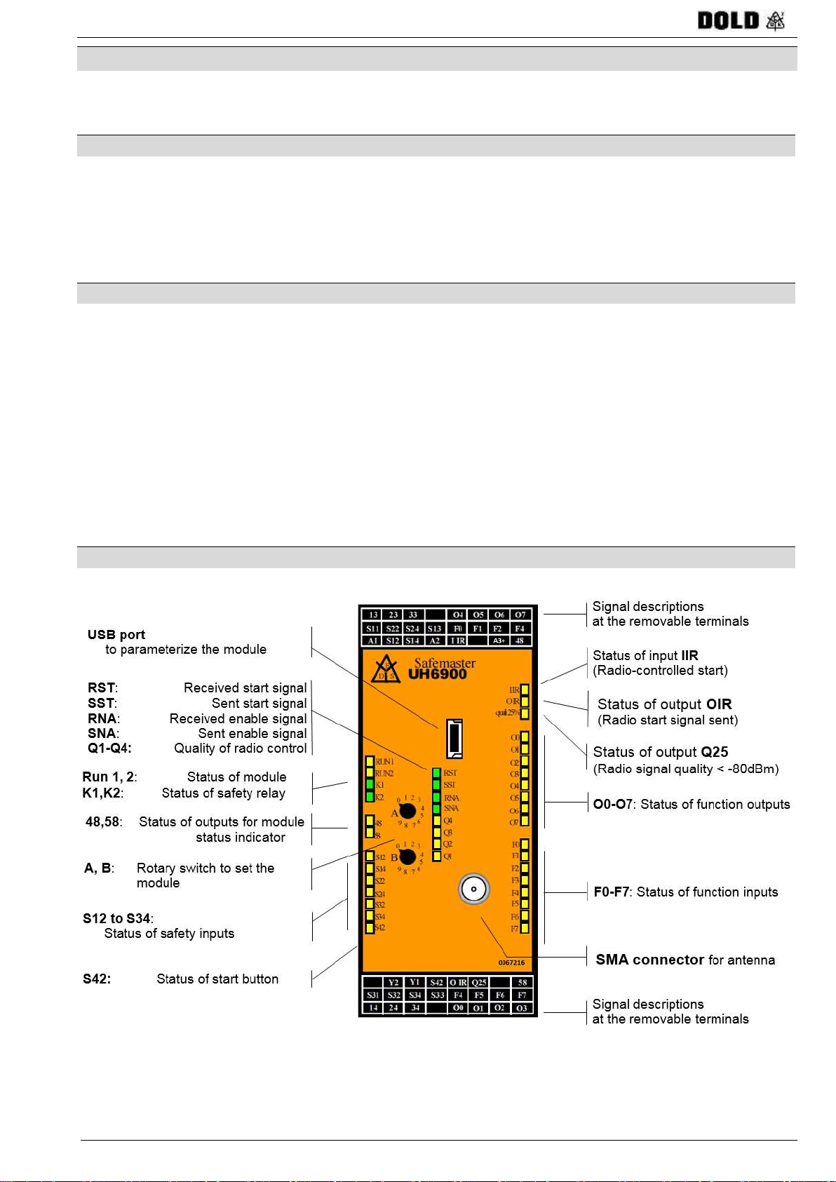
2.3 Front view UH 6900.......................................................................................................6
2.4 Installation SAFEMASTER W Manger...........................................................................7
2.5 Main operation modes...................................................................................................7
2.5.1 Full safety operation...............................................................................................7
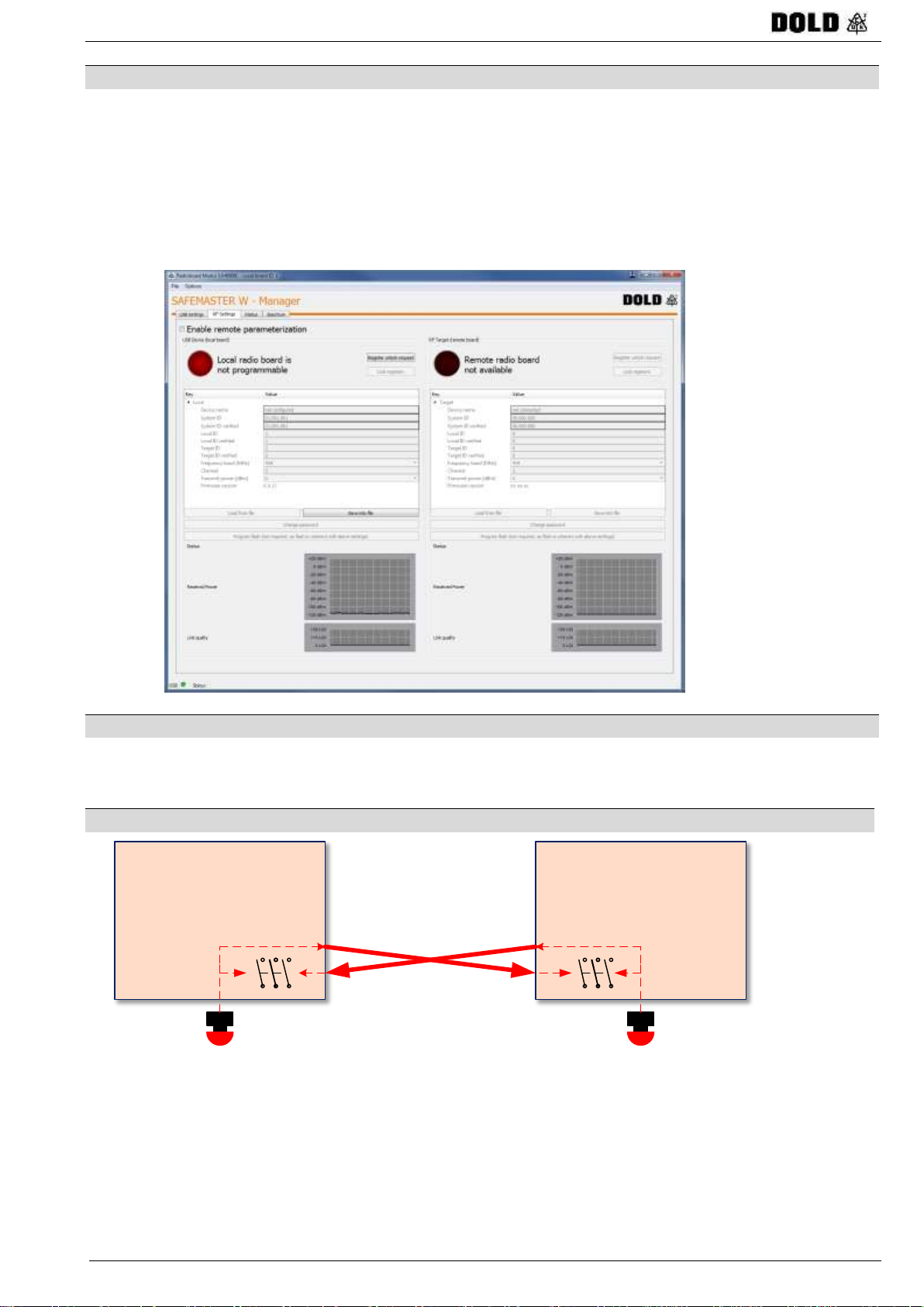
2.5.2 Cross operation......................................................................................................8
2.5.3 Safety operation with optional radio control............................................................8
2.6 Connections and oprating modes..................................................................................9
2.7 Parameterization .........................................................................................................10
2.7.1 Frequency channel...............................................................................................11
2.7.2 Integrated spectrum analyzer...............................................................................12
2.7.3 Further adjustments .............................................................................................13
2.7.4 Programming........................................................................................................13
2.8 Power on and standby test..........................................................................................14
3Introduction of the system..........................................................................15
3.1 Directives, standards, and certification........................................................................15
3.2 Applications, intended use...........................................................................................15
3.3 Design .........................................................................................................................16
3.4 Functions.....................................................................................................................16
4System description......................................................................................17
4.1 Design and functions of the UH 6900 radio-controlled safety module.........................17
4.1.1 Main features of the UH 6900 radio-controlled safety module..............................17
4.1.2 Inputs and outputs................................................................................................18
4.1.3 Overview UH 6900 radio-controlled safety module; front view.............................18
4.1.4 Detection of safety elements................................................................................18
4.1.5 Start options.........................................................................................................19
4.1.5.1 Manual start and reset........................................................................................19
4.1.5.2 Auto start............................................................................................................19
4.1.5.3 Two-hand............................................................................................................19
4.1.5.4 Start via radio .....................................................................................................19
4.1.6 Semiconductor outputs.........................................................................................20
4.1.7 Assignment of function inputs to semiconductor outputs......................................20
4.1.8 Identity code.........................................................................................................20
4.1.9 Receiver antenna.................................................................................................20
4.1.10 Radio frequency...................................................................................................20
4.1.11 Transmitter power ................................................................................................20
5Installation and connection ........................................................................21
5.1 Important notes on installation and connection............................................................21
5.2 Wiring..........................................................................................................................21
5.3 Protection of power supply ..........................................................................................21
5.4 Positioning of the radio-controlled safety module and the antenna .............................22
5.4.1 Positioning of the radio-controlled safety module.................................................22
5.4.2 Distribution of radio signals ..................................................................................22
5.4.3 Positioning of antenna..........................................................................................22
5.5 Terminal connections of the radio-controlled safety module........................................23
5.6 Connection of safety elements ....................................................................................23
5.7 Installation / removal of the PS / PC terminals.............................................................24
5.8 Minimum and maximum output currents......................................................................24

SAFEMASTER W Radio controlled safety module UH 6900
0274164 / 13.03.17 en / RV_800 3
5.9 Disturbance protection.................................................................................................24
6Commissioning (operating manual)...........................................................25
6.1 General instructions for commissioning.......................................................................25
6.1.1 Close-by machines equipped with SAFEMASTER W systems............................25
6.2 Configuration at shipment............................................................................................26
6.2.1 Display of identity code ........................................................................................26
6.2.2 Selection and setting of the radio frequency.........................................................26
6.2.2.1 Set the radio frequency.......................................................................................26
6.2.2.2 Set the transmitter power:...................................................................................27
6.3 Wiring and connection options.....................................................................................27
6.3.1 Connection of power supply.................................................................................27
6.3.2 Connection of safety elements.............................................................................27
6.3.2.1 Connection of emergency stop push-buttons .....................................................27
6.3.2.2 Connection of safety gates.................................................................................28
6.3.2.3 Connection of LC type 4 in accordance with EN 61 496.....................................28
6.3.2.3.1 Calculation of the safety distance of an LC connected to a UH 6900.........28
6.3.2.4 Connection of two-hand control IIIA in accordance with DIN EN 574.................29
6.3.3 Connection of the start button ..............................................................................29
6.3.4 Connection of an additional start control over IR or LC........................................29
6.3.5 Operation with or without external contact reinforcement.....................................30
6.3.6 Connection of non-safety-relevant function inputs................................................30
6.3.7 Connection of status indicators ............................................................................30
6.3.8 Connection of non-safety-relevant function outputs .............................................31
6.4 Setup and commissioning of the UH 6900 radio-controlled safety module..................32
6.4.1 Operating mode: 'Full safety operation'................................................................33
6.4.1.1 Set-up of safety inputs and start mode...............................................................33
6.4.1.2 Application examples..........................................................................................34
6.4.1.3 Function diagrams..............................................................................................35
6.4.1.3.1 Full safety operation without two-hand control ...........................................35
6.4.1.3.2 Full safety operation with two-hand control ................................................35
6.4.2 Operating mode: 'Cross-operation'.......................................................................36
6.4.2.1 Set-up of safety inputs and start mode...............................................................37
6.4.2.2 Application examples..........................................................................................38
6.4.2.3 Function diagrams..............................................................................................39
6.4.2.3.1 Cross-operation without two-hand control..................................................39
6.4.2.3.2 Cross-operation with two-hand control, manual start, and auto start..........39
6.4.2.3.3 Cross-operation with two-hand control and auto start only.........................40
6.4.3 ‘Safety operation with optional radio control’ mode of operation ..........................41
6.4.3.1 Setting the start mode and the radio activation time...........................................43
6.4.3.2 Application examples..........................................................................................44
6.4.3.3 Function diagrams..............................................................................................45
6.4.3.3.1 Setting A = 4: 2 x manual start, reset of remote deactivation through control
module 45
6.4.3.3.2 Setting A = 5: 2 x manual start, reset of remote deactivation with S42 after
reset on control module...............................................................................................46
6.4.3.3.3 Setting A = 6: 2 x manual start, reset of all deactivations also on control
module 47
6.4.3.3.4 Setting A = 7: 2 x auto start, reset of remote deactivation on control module
48
6.4.3.3.5 Setting A = 8: 2 x auto start, reset of remote deactivation through S42 after
reset on control module...............................................................................................49
7Troubleshooting ..........................................................................................50
7.1 Display and status indicators on UH 6900 radio-controlled safety module..................50
7.2 Status and error codes ................................................................................................51
7.2.1 System errors in safety operation.........................................................................51
7.2.2 Status indicator.....................................................................................................52

SAFEMASTER W Radio controlled safety module UH 6900
0274164 / 13.03.17 en / RV_800 4
8Parameterization and diagnosis of radio features....................................53
8.1 Parameterization software ‘UH 6900 Radio Board’ .....................................................53
8.1.1 Computer HARDWARE requirements..................................................................53
8.1.2 Installation of parameterization software..............................................................53
8.2 RF Settings window.....................................................................................................54
8.2.1 Display of radio parameters..................................................................................54
8.2.1.1 Device names.....................................................................................................55
8.2.1.2 System codes of the devices..............................................................................55
8.2.1.3 Device code and target device code...................................................................55
8.2.1.4 Frequency band..................................................................................................55
8.2.1.5 Frequency channel.............................................................................................55
8.2.1.6 Transmitter power...............................................................................................55
8.2.1.7 Received transmitter power................................................................................55
8.2.1.8 Software version.................................................................................................55
8.2.2 Setting of radio parameters..................................................................................56
8.2.2.1 Device names.....................................................................................................58
8.2.2.2 Frequency channel.............................................................................................59
8.2.2.2.1 List of available frequencies in the 433 MHz band.....................................59
8.2.2.2.2 List of available frequencies in the 869 MHz band.....................................59
8.2.2.3 Transmitter power...............................................................................................60
8.3 STATUS screen (diagnostic function)..........................................................................62
8.4 Spectrum screen (diagnotic function) ..........................................................................62
9Technical data..............................................................................................64
9.1 Safety related data ......................................................................................................67
9.2 Dimension drawing......................................................................................................67
10 Order information........................................................................................68
10.1 Wireless Safety System...............................................................................................68
10.1.1 Standard type.......................................................................................................68
10.1.2 Example for ordering variations............................................................................68
10.2 Accessories.................................................................................................................68
11 Maintenance and care.................................................................................69
12 Disclaimer and warranty .............................................................................69
13 CE declaration of conformity......................................................................70

SAFEMASTER W Radio controlled safety module UH 6900
0274164 / 13.03.17 en / RV_800 5
1 Important Notes
This manual is for your safety and for the safety of the plant operators. Read this manual
carefully before you install or commission the SAFEMASTER W system and use it when
working on the protected machine or equipment.
If you encounter technical problems, please contact our customer service at: +49 77 23 / 654-0;
Fax: +49 77 23 / 654-356;
1.1 General safety instructions
SAFEMASTER W must only be installed and set up by authorized and skilled
personnel
- that is familiar with the correct and proper handling of safety components,
- that is familiar with the relevant regulations and standards for safety at work and
accident prevention and has read and understood this user manual.
The operator must be adequately trained and authorized to operate the
machine.
A visible emergency stop button must always be functional.
In some operating modes, one of the two modules is temporarily not functional,
therefore precautions must be taken to ensure that any emergency stop devices
connected there are not visible.
The operator must have a clear overview of the hazard zone at all times.
If the operator’s direct view on the relevant equipment or plant parts is restricted in
any way, for example the view on the access to the machine, on the drilling/milling
head, etc., that is, if such areas cannot be seen from all operator positions, we
recommend the installation of an additional position indicator, for example a light
curtain. Then, zones with a good overview can be defined as start zones. The
application can be started from within these zones only.
The operator must be able to switch off the machine all the time
While starting the machine or during operation the operator must always be able to
reach the emergency stop button.
Restarting the machine
After the machine was shut down by the safety function of the wireless
SAFEMASTER W safety system, the machine must not be restarted by resetting
the start button before the reason for the shut-down is detected and the problem
solved.
If more than one wireless systems are used at the same location, the different
systems must be set up for different radio frequencies. There must be at least one
blank channel between two active ones (for example, use channels 5, 7, 9, etc.).
•The equipment must be handled with care and be checked in regular
intervals, depending on the usage and as necessary.
You, as the installer of the machine or plant, must make clear reference to
these safety instructions in the relevant operating manual.
1.2 Disposal
Unserviceable devices that cannot be repaired must be disposed in accordance with the
relevant country-specific waste disposal regulations.

SAFEMASTER W Radio controlled safety module UH 6900
0274164 / 13.03.17 en / RV_800 6
2 Quick guide
A brief overview of the system and instructions for the initial set-up procedure in just a few
steps using a simple example configuration.
2.1 Components list
In the delivery, you will receive:
2 UH 6900 modules,
2 antennas with connection adapters or connection cables,
1 CD with SAFEMASTER W Manager software, handbook, and license key,
Any separate accessories (e.g. light barrier)
2.2 Configuration at delivery
The modules are always delivered with the following configuration:
Operating mode: Complete protected mode (rotary switch A=0, rotary switch
B=0)
Device name: not yet assigned
Radio channel: Channel 05, 433.200 MHz (or 869.8125 MHz)
Transmission power: 0 dBm (1 mW)
This configuration must be adjusted according to the desired system installation using the
provided software or the rotary switch on the front of the module.
The identification numbers (system ID, device ID and target device ID) are already assigned
and cannot be changed
2.3 Front view UH 6900

SAFEMASTER W Radio controlled safety module UH 6900
0274164 / 13.03.17 en / RV_800 7
2.4 Installation of SAFEMASTER W Manger
Insert the included CD and install the SAFEMASTER W Manager on your PC (Windows
operating system). The installation will start automatically, or you can also call up the
setup file manually.
A program folder will be created on your PC, and the program will be added to the start
menu.
Start the SAFEMASTER W Manager and enter the license key, which is found in a text
file on the CD. Then the program will be ready for operation.
2.5 Main operation modes
The modules always work in pairs using bidirectional safety radio transmission. In general,
there are three different operating modes available.
2.5.1 Full safety operation
„Kompletter Schutzbetrieb“
UH6900
„Kompletter Schutzbetrieb“
UH6900
One safety circuit
Safety inputs influence the local and remote controlled safety output
Configurable start options:
- Manual, automatic, two-handed, additional IR enable signal
see chapter 6.4.1 Operating mode: 'Full safety operation'

SAFEMASTER W Radio controlled safety module UH 6900
0274164 / 13.03.17 en / RV_800 8
2.5.2 Cross operation
„Kreuzbetrieb“
UH6900
„Kreuzbetrieb“
UH6900
Two independent safety circuits
Safety inputs influence the remote controlled safety output
Configurable start options:
- Manual, automatic, two-handed, additional IR enable signal
see chapter 6.4.2 Operating mode: ‘Cross operation’
2.5.3 Safety operation with optional radio control
„Kreuzbetrieb“
UH6900
„Zuschaltbarer Funkbetrieb“
UH6900
One safety circuit
One modulator unit and one receiver unit
Safety inputs influence safety output on the receiver unit
Modulator unit connectable with activated safety output
Configurable start options:
- Manual, automatic, two-handed, additional IR enable signal
see chapter 6.4.3 ‘Safety operation with optional radio control’ mode of operation

SAFEMASTER W Radio controlled safety module UH 6900
0274164 / 13.03.17 en / RV_800 9
2.6 Connections and oprating modes
For the initial start-up procedure, at least the voltage supply (A1, A2), 1 safety
transmitter, a start signal transmitter, the Y1, Y2 bridge and the antenna must be
connected. The unused safety inputs 2 and 3 must be bridged.
0067213
RNA
SNA
RST
SST
Q4
Q3
Q2
Q1
A1
S12
S14
A2
S11
S22
S24
S13
13
23
33
I IR
A3+
48
F0
F1
F2
F4
O4
O5
O7
Safemaster
E
D
S
UH6900
14
24
34
S31
S32
S34
S33
Y2
Y1
S42
O IR
58
F4
F5
F6
F7
O0
O1
O2
O3
Q25
B
A
F0
F3
F1
F2
F4
F7
F5
F6
O0
O3
O1
O2
O4
O7
O5
O6
IIR
OIR
quali25%
RUN1
RUN2
K1
K2
S12
48
S14
S32
S22
58
S24
S34
S42
0
9
8
1
6
7
2
3
4
5
0
9
8
1
7
2
3
4
5
6
O6
A1 A2
+24V
GND
Power Supply
Ext. Contact Reinforcement
Y2 Y1
Safety Input 2
S11 S22 S13 S24
0067213
RNA
SNA
RST
SST
Q4
Q3
Q2
Q1
A1
S12
S14
A2
S11
S22
S24
S13
13
23
33
I IR
A3+
48
F0
F1
F2
F4
O4
O5
O7
Safemaster
E
D
S
UH6900
14
24
34
S31
S32
S34
S33
Y2
Y1
S42
O IR
58
F4
F5
F6
F7
O0
O1
O2
O3
Q25
B
A
F0
F3
F1
F2
F4
F7
F5
F6
O0
O3
O1
O2
O4
O7
O5
O6
IIR
OIR
quali25%
RUN1
RUN2
K1
K2
S12
48
S14
S32
S22
58
S24
S34
S42
0
9
8
1
6
7
2
3
4
5
0
9
8
1
7
2
3
4
5
6
O6
A1 A2
+24V
GND
Power Supply
Safety Input 3
S31 S32 S33 S34
Ext. Contact Reinforcement
Y2 Y1
Safety Input 2
S11 S22 S13 S24
Safety Input 3
S31 S32 S33 S34
Start-Button
S42 A1
Start
Start-Button
S42 A1
Start
Safety Input 1
S11 S12 S14 S13
Stop
Safety Input 1
S11 S12 S14 S13
Stop
Before switching on, please check the position of the rotary switch (A=0, B=0).
Switch the module on.
- If the setting is correct, the LEDs RUN1, RUN2, 48, and 58 will flash slowly to indicate
that the module is ready for operation.
- If the setting is incorrect, the LEDs RUN1, RUN2, 48 and 58 will issue an error code
(see chapter 7 „Troubleshooting“)
Remark: An exact description of wiring and connection options is provided in chapter 5.5
„Terminal connections of the radio-controlled safety module" and chapter 6.3
„Wiring and connection options“

SAFEMASTER W Radio controlled safety module UH 6900
0274164 / 13.03.17 en / RV_800 10
2.7 Parameterization
Connect both UH 6900 modules at the same time or in succession to your PC via USB to
complete parameterization.
For simultaneous parameterization, the SAFEMASTER W Manager can be started twice
so that you can access both devices in parallel.
If there is already a radio connection, it is possible to access both modules with one
instance of SAFEMASTER W Manager.
Select the tab “RF settings”
Open the tab and enter the password.
The standard password upon delivery is “0000.”
Remark: It is best to change the password immediately to ensure that only authorized
personnel can change the parameters.

SAFEMASTER W Radio controlled safety module UH 6900
0274164 / 13.03.17 en / RV_800 11
After opening the tab, you can change the device name, frequency channel, and
transmission power.
2.7.1 Frequency channel
The modules can only communicate with one another if they are both set to the same
channel, if they emit sufficient transmission power, and if they are not disrupted by
other devices transmitting on the same channel.
Therefore, it is necessary to prepare a frequency plan for the entire system in order to
avoid mutual disturbances by devices.
Channel 5 is set at delivery. Change this channel according to your specifications.
Permitted values are 1..64 in the 433 MHz range and 1..12 in the 869 MHz range

SAFEMASTER W Radio controlled safety module UH 6900
0274164 / 13.03.17 en / RV_800 12
2.7.2 Integrated spectrum analyzer
You can use the integrated frequency analyzer to quickly check the set channels and
frequencies in your system environment. It will go through all channels in the frequency range
and measure the received power. This allows you to very easily determine which channels
are already in use.
However, this measurement in no way replaces an exact frequency plan of your system.
Select the spectrum analyzer by switching to the “Spectrum” tab.
Turn on the spectrum analysis.
It will take approximately 50 seconds to go through all 64 channels.
The example shows one transmitter on channel 5 and another on channel 10.

SAFEMASTER W Radio controlled safety module UH 6900
0274164 / 13.03.17 en / RV_800 13
2.7.3 Further adjustments
The transmission power and device name do not have to be changed for initial start-up
2.7.4 Programming
If the channel was changed in the prvious step, this setting must be permanently saved in the
device. The programmer button will now appear blue. The status window will indicate that the
programming was successful.

SAFEMASTER W Radio controlled safety module UH 6900
0274164 / 13.03.17 en / RV_800 14
2.8 Power on and standby test
After successful parameterization and after switching on the modules once again, the LEDs
RUN1, RUN2, 48, and 58 shoudl flash slowly to indicate they are ready for operation.
If there is an error, these LEDs will show different flashing codes.
see chapter 7.2 „Status and error codes“
Press the start button on one of the two devices
The safety relays on both devices activate
Press the emergency stop button on one of the two devices
The safety relays on both devices deactivate
For further controlling, you can check the current status of the transmission path using the
SAFEMASTER W Manager.
If the connection was established successfully, both modules will be displayed in the
window with the set parameters.

SAFEMASTER W Radio controlled safety module UH 6900
0274164 / 13.03.17 en / RV_800 15
3 Introduction of the system
SAFEMASTER W – is an innovative wireless safety system to protect man and machine. A
feature of the Wireless Safety System is its safety-oriented bi-directional radio transmission
for transmitting signals between two wireless safety modules so that the two separate safety
devices, each of them installed on a different machine part that is not connected to the other by
wires (for example, moving machine parts), work together as one system. In addition, the
systems allows the configuration of different operating modes.
SAFEMASTER W definitely solves the problem of wear on trailing cables without the
necessity to compromise safety and response time.
3.1 Directives, standards, and certification
The Wireless Safety System SAFEMASTER W meets all the safety requirements of the
currently valid directives and standards.
•Machine directive 2006/42/EC
•IEC/EN ISO 13 849-1: Category 4, Performance Level “e”
•IEC/EN 61 508: SIL Claim Limit SIL 3
•IEC/EN 61 511: SIL Claim Limit SIL 3
•IEC/EN 62 061: Safety Integrity Level SIL CL 3
•DIN EN 574: Safety of machinery – Two-hand control devices –
Furthermore, the Wireless Safety System SAFEMASTER W is in accordance with the standard
•DIN EN 300 220 Electromagnetic compatibility and Radio spectrum Matters (ERM)
– Short Range Devices (SRD) –
Radio equipment to be used in the 25 MHz to 1 000 MHz
frequency range with power levels ranging up to 500 mW
Please note: Validation according to DIN EN ISO 13849-2 is always required for the complete
system.
3.2 Applications, intended use
Typical applications of SAFEMASTER W are:
Hazard areas where protective equipment is necessary for the safety of persons but
where wiring is impossible or not reasonable, for example in applications with extremely
wide-spread, extensive hazard zones;
Mobile and stationary plants and equipment, for example large machines, assembly halls
and scaffolds, conveyor belts, high-rack warehouses, warehouses, forklifts, etc.
The UH 6900 radio-controlled safety modules are intended for the wireless remote control of
machines and plant parts that used to be controlled by cable. Their usage is only restricted by
valid safety instructions that prohibit, for example, staying under suspended loads.
The radio transmission range is approx. 800 m in the free field and approx. 150 m in an
industrial environment.

SAFEMASTER W Radio controlled safety module UH 6900
0274164 / 13.03.17 en / RV_800 16
3.3 Design
The main components of the safety system are the two radio-controlled safety modules.
Each UH 6900 radio-controlled safety module is installed in a switch cabinet or on a mobile
device and is operated with a plug-in or external antenna. It detects the signals of up to three
wired safety elements plus the signals from the related second active radio-controlled safety
module that are sent through a safe radio transmission. Safety-relevant switching commands
are switched by relay outputs, non-safety-relevant control signals through semiconductor
outputs.
In addition to the up to three 2-channel safety devices, there are 8 non-safety function inputs
(DC 24 V) and 8 non-safety function outputs (semiconductor outputs, DC 24 V), whose states
are transmitted or received through the safe radio transmission. LEDs inform about the states
of all inputs and outputs and indicate the current state of the internal radio-controlled safety
module.
The current state of the UH 6900 radio-controlled safety module is also indicated by two non-
safety-relevant semiconductor outputs.
In addition, a non-contact sender and a non-contact receiver (for example, light curtain or infra-
red sender and receiver) may be connected to force the system to start from a specific location
via radio.
3.4 Functions
The modules allows the selection of three different main operating modes by a rotary switch.
Full safety operation
Cross-operation
Safety operation with optional radio control
For each of these operating modes, the start mode (auto start, manual start, or start by two-
hand control) of the module can also be selected by the rotary switch.
The individual operating modes are described in more detail in section 6.4 Setup and
commissioning of the UH 6900 radio-controlled safety module.
The UH 6900 radio-controlled safety module is equipped with a DC 24 V semiconductor output
OIR that reproduces the start signal to enable the safety relay.
As an additional accident prevention measure, all of the above-mentioned operating modes can
be set to detect this additional start signal from the opposite side via the DC 24 V IIR input.This
allows, for example, the determination of start areas by the use of a light curtain or infra-red
sender and receiver. Only from these start areas, the application can be started via radio.
For a successful start, the system then requires a start signal at the IIR input in addition to the
start signal via the safety radio transmission.

SAFEMASTER W Radio controlled safety module UH 6900
0274164 / 13.03.17 en / RV_800 17
4 System description
4.1 Design and functions of the UH 6900 radio-controlled safety module
4.1.1 Main features of the UH 6900 radio-controlled safety module
Depending on the operating mode, to connect:
- Emergency-stop push-button (2-channel), safety gate, LC (non-contact safety
system, for example light curtain) of the type 4 in accordance with EN 61 496 or the
two-hand type IIIA in accordance with DIN EN 574.
- 1 start button
- Changeover switch (2-channel) to indicate radio use in the ‘Safety operation with
optional radio control’operating mode
For two-way communication via radio:
- Safety shut-down commands
- Signals from 8 non-safety-relevant DC 24 V inputs at 8 non-safety-relevant DC 24 V
semiconductor outputs
Broken wire and short circuit detection with fault indication
Semiconductor output to indicate poor or no radio control
2 semiconductor outputs for status indication
LEDs to indicate status of module
LEDs to indicate status of all inputs and outputs
LEDs to indicate the radio transmission and its quality
45 mm in width
Compact device easy to install
Mounting on profile DIN rail
Removable screw terminal blocks
Functions that can be selected by rotary switches:
- ‘Full safety operation’ with different start modes (two-hand type IIIA and/or manual start,
auto start)
- ‘Cross-operation’ with different start modes (two-hand type IIIA and/or manual start, auto
start)
- ‘Safety operation with optional radio control’ with different start modes (manual start on
S42, manual start via radio, or auto start)
- Valid for all operating modes:
Radio start function via radio with or without detection of an additional start signal at the
IIR input.
Frequency range 433 MHz or 869 MHz (license-free radio frequencies)
Radio channel, transmitter power, and module name can be set by means of a
parameterization software
Status indicator for the devices connected via radio, by means of the parameterization
software including status of radio transmission quality

SAFEMASTER W Radio controlled safety module UH 6900
0274164 / 13.03.17 en / RV_800 18
4.1.2 Inputs and outputs
Inputs
- 3 two-channel safety inputs DC 24 V
- 1 DC 24 V input for start button
- 1 feedback circuit to monitor external relays
- 1 DC 24 V input that can be used as start signal in addition to the start signal received via
radio.
- 8 non-safety-relevant DC 24 V functional inputs, the status of which is sent to the opposite
side.
Outputs
- 3 safety-relevant NO contacts or
2 safety-relevant NO contacts + 1 NC contact (can only be used as an indicator contact)
- 1 DC 24 V semiconductor output that reproduces the start signal sent via radio as an
additional start signal for the release of the safety relay on the opposite side
- 8 non-safety-relevant DC 24 V semiconductor outputs that are controlled by the opposite side
- 2 DC 24 V semiconductor outputs to display the status of the radio-controlled safety module
- 1 non-safety-relevant DC 24 V semiconductor output to indicate poor or no radio control
4.1.3 Overview UH 6900 radio-controlled safety module; front view
4.1.4 Detection of safety elements
If the radio-controlled safety module is switched off through a hard-wired safety element (for
example, the emergency stop push-button) the following requirements must be met for a
restart:
Both control signals of the operated 2-channel safety element must have been switched off
simultaneously (open contact). Restart (closed contact) of the two signals must take place
within 3 s (in case of two-hand, 500 ms).
If the control signals of the safety elements are already applied when power is switched on, the
safety elements meet the start requirements.
Any specifics regarding the detection of the safety signals based on the selected modes of
operation are mentioned in the descriptions of the operating modes.
Status of output OIR
(Radio start signal sent)
USB port
to parameterize the module
Signal descriptions
at the removable terminals
Run 1, 2: Status of module
K1,K2: Status of safety relay
48,58: Status of outputs for module
status indicator
Status of input IIR
(Radio-controlled start)
A, B: Rotary switch to set the
module
Status of output Q25
(Radio signal quality < -80dBm)
O0-O7: Status of function outputs
F0-F7: Status of function inputs
RST: Received start signal
SST: Sent start signal
RNA: Received enable signal
SNA: Sent enable signal
Q1-Q4: Quality of radio control
S12 to S34:
Status of safety inputs
S42: Status of start button
SMA connector for antenna
Signal descriptions
at the removable terminals

SAFEMASTER W Radio controlled safety module UH 6900
0274164 / 13.03.17 en / RV_800 19
4.1.5 Start options
4.1.5.1 Manual start and reset
The start button to be connected to terminal S42 is used for the manual start and also to reset
the radio-controlled safety module. The maximum activation time for the start buttons is 3 sec. If
the button is pressed longer than 3 sec., the unit will not start. A start button must not be
pressed when power is being applied to the UH 6900 radio-controlled safety module.
4.1.5.2 Auto start
The safety inputs S12-S14, S22-S24 and S32-S34 can be set up for automatic start (see
operating modes). This means that the radio-controlled safety module UH 6900 enables the
safety relays as soon as the safety function is active again (for example, the safety gate is
closed again).
4.1.5.3 Two-hand
In some operating modes, the safety input on S12-S14 can be used for a two-hand control of
the type III A.
In this case, the following steps - in the order prescribed below - must be carried out each time
a safety relay is disabled:
The two-hand buttons must be released.
All other safety inputs must be closed again and (if they are set to manual start) reset.
Only now, the safety relays can be enabled again by the two-hand control.
If this order is not observed the safety relays will not start.
4.1.5.4 Start via radio
Starting the plant or machine must be limited to a specific start zone with a good
overview of the hazard zone.
If one of the radio-controlled safety modules is installed on a mobile device (for
example a fork-lift truck) and if it is intended that starting via radio is possible from that
device as well, enabling start through the IIR input is the best option. For example, the
output of an infra-red receiver can be connected to this input when the related infra-red
sender is controlled by the OIR output of the other radio-controlled safety module. This
forces the operator to go to the defined start zone.
When this option is selected the receiver of the start signal waits for 2 conditions to be
fulfilled before the safety relay is enabled:
1. Receipt of a valid start command sequence.
2. Detection of a start signal at the IIR input that fetches to the received start
sequence.
If this start signal IIR is used with a two-hand control in the safety system, this option must
be activated at the module, with the connected two-hand control buttons.
Table of contents
Popular Security Sensor manuals by other brands

PCE Health and Fitness
PCE Health and Fitness PCE-LDC 8 user manual

System Sensor
System Sensor SPECTRAlert CH24 Series Installation and maintenance instructions

BRS
BRS BRS-6 600 owner's manual

Para systems
Para systems MINUTEMAN SSL-SMOKE user manual

SPX
SPX RADIODETECTION RD8200SG Operation manual

LLOYTRON
LLOYTRON MIP SYSTEM 3 B7835 operating instructions